EP1693018A1 - Element de flexion, mecanisme a joint coulissant multiarticule, actionneur et manipulateur - Google Patents
Element de flexion, mecanisme a joint coulissant multiarticule, actionneur et manipulateur Download PDFInfo
- Publication number
- EP1693018A1 EP1693018A1 EP04806959A EP04806959A EP1693018A1 EP 1693018 A1 EP1693018 A1 EP 1693018A1 EP 04806959 A EP04806959 A EP 04806959A EP 04806959 A EP04806959 A EP 04806959A EP 1693018 A1 EP1693018 A1 EP 1693018A1
- Authority
- EP
- European Patent Office
- Prior art keywords
- drive power
- articulation
- constructed
- bending action
- bending
- Prior art date
- Legal status (The legal status is an assumption and is not a legal conclusion. Google has not performed a legal analysis and makes no representation as to the accuracy of the status listed.)
- Withdrawn
Links
Images




Classifications
-
- A—HUMAN NECESSITIES
- A61—MEDICAL OR VETERINARY SCIENCE; HYGIENE
- A61B—DIAGNOSIS; SURGERY; IDENTIFICATION
- A61B17/00—Surgical instruments, devices or methods
- A61B17/28—Surgical forceps
- A61B17/29—Forceps for use in minimally invasive surgery
-
- A—HUMAN NECESSITIES
- A61—MEDICAL OR VETERINARY SCIENCE; HYGIENE
- A61B—DIAGNOSIS; SURGERY; IDENTIFICATION
- A61B34/00—Computer-aided surgery; Manipulators or robots specially adapted for use in surgery
- A61B34/70—Manipulators specially adapted for use in surgery
-
- A—HUMAN NECESSITIES
- A61—MEDICAL OR VETERINARY SCIENCE; HYGIENE
- A61B—DIAGNOSIS; SURGERY; IDENTIFICATION
- A61B17/00—Surgical instruments, devices or methods
- A61B17/00234—Surgical instruments, devices or methods for minimally invasive surgery
- A61B2017/00292—Surgical instruments, devices or methods for minimally invasive surgery mounted on or guided by flexible, e.g. catheter-like, means
- A61B2017/003—Steerable
-
- A—HUMAN NECESSITIES
- A61—MEDICAL OR VETERINARY SCIENCE; HYGIENE
- A61B—DIAGNOSIS; SURGERY; IDENTIFICATION
- A61B17/00—Surgical instruments, devices or methods
- A61B2017/0046—Surgical instruments, devices or methods with a releasable handle; with handle and operating part separable
-
- A—HUMAN NECESSITIES
- A61—MEDICAL OR VETERINARY SCIENCE; HYGIENE
- A61B—DIAGNOSIS; SURGERY; IDENTIFICATION
- A61B17/00—Surgical instruments, devices or methods
- A61B2017/00477—Coupling
-
- A—HUMAN NECESSITIES
- A61—MEDICAL OR VETERINARY SCIENCE; HYGIENE
- A61B—DIAGNOSIS; SURGERY; IDENTIFICATION
- A61B17/00—Surgical instruments, devices or methods
- A61B17/28—Surgical forceps
- A61B17/29—Forceps for use in minimally invasive surgery
- A61B2017/2901—Details of shaft
- A61B2017/2905—Details of shaft flexible
-
- A—HUMAN NECESSITIES
- A61—MEDICAL OR VETERINARY SCIENCE; HYGIENE
- A61B—DIAGNOSIS; SURGERY; IDENTIFICATION
- A61B17/00—Surgical instruments, devices or methods
- A61B17/28—Surgical forceps
- A61B17/29—Forceps for use in minimally invasive surgery
- A61B2017/2901—Details of shaft
- A61B2017/2908—Multiple segments connected by articulations
Definitions
- the present invention relates to a bending action member, multi-slider linkage mechanism, actuator and manipulator and more particularly the present invention can be preferably applied to a manipulator used in operation such that it is inserted into a space having a higher pressure than the atmospheric pressure. Further, the present invention is preferably applied to a manipulator having multi-slider linkage mechanism which has a plurality of articulation and starts bending action of its rear end side after the bending action of its front end side of the adjoining two articulations ends. Additionally, the present invention is preferably applied to a manipulator used for medical purpose such as minimally invasive surgery.
- the minimally invasive surgery having an advantage of reducing a damage to the patient has various problems for achieving minimally invasive property.
- Those problems originate from mainly a low degree of freedom possessed by such a surgical instrument such as a laparoscope and long forceps used in operative treatment.
- the bending mechanism having a degree of freedom of the slider-link mechanism is constituted of three frames 101, 102, 103, two-pin rotary shafts 104, 105 (2-pin joints) capable of rotating at an angle of ⁇ 45°, drive link joints 106, 107, 108, and restraint link joints 109, 110.
- a moment about the rotary shaft 104, 105 are given to' the respective frames 101, 102, 103 by sliding the drive link joint 108 in a predetermined direction.
- the restraint link joints 109, 110 are link joints for restricting the operation so as to allow the second frame to start rotation after the frame 101 at the front end side rotates by ⁇ 45°.
- Such a structure allows a degree of freedom to bend by ⁇ 90° to both sides.
- a manipulator capable of bending up to 90° independently can be constructed by jointing two bending mechanism with one degree of freedom back and forth so that they are located at 90° each other in the bending direction.
- a manipulator provided with a surgery instrument at a movable portion at its front end is introduced into the abdominal cavity through an incised hole in the stomach wall, the pressure inside the abdominal cavity is set higher than the atmospheric pressure to secure a space for expanding the field of vision and executing operation in order to facilitate the operation.
- space for example, wedge-shaped portion
- a drive power needs to be transmitted to the movable portion at the front end portion to actuate this frame.
- a link member such as a drive link joint 108 is required.
- a pipe having a hollow portion that connects the link member to the movable portion and hold and accommodates this up to its front end portion is necessary.
- the inventor of the present invention has paid attention to the restrictions on the structure of the manipulator and found that leakage of air in space having a higher pressure than the atmospheric pressure to outside through the hollow portion in the bent portion of the frame and pipe is one of causes for leakage of air in the abdominal cavity.
- the above-mentioned problem occurs not only in the minimally invasive surgery but also in case where the front end portion of the manipulator or the front end portion of a bending action member constructed to be detachable from the manipulator is introduced into space having a higher pressure than the surrounding pressure and driven.
- an object of the present invention is to provide a bending action member and manipulator capable of maintaining the pressure of space having a high pressure by preventing air in the high pressure area from leaking to outside through the bending action member or a movable means of the manipulator when the bending action member or the front end portion of the manipulator is introduced into the space having higher pressure than the surrounding pressure.
- the multi-slider linkage mechanism comprises three frames 101, 102, 103 whose end portion is cut out at a predetermined angle and two articulation portions in which these frames 101, 102, 103 are jointed each other.
- a first articulation portion 201 executes bending action and after the bending action of the first articulation portion 201 ends, the bending action of the second articulation portion 202 is executed. That is, it is so constructed that the bending action of the second articulation portion 202 is not started until the bending action of the first articulation portion 201 is completed.
- the secondarticulationportion202 is bent before the bending action of the first articulation portion 201 ends by receiving the weights of the frames 101, 102, 103 and other external forces as shown in FIG. 7B, so that it is sometimes bent slightly in an opposite direction with respect to the its proper bending direction of the second articulation portion 202.
- an angle ⁇ 2 between the restraint link 109 and the inner wall surface of the frame 102 becomes larger than an angle ⁇ 1 at the time when the ordinary bending action is carried out as shown in FIG. 7A.
- a second object of the present invention is to provide a multi-slider linkage mechanism capable of actuating an apparatus having the multi-slider linkage mechanism smoothly and stably by smoothing the operation of the mechanism in order to prevent an unexpected stop of the bending action by suppressing generation of hang-up phenomenon (scuffing phenomenon) in the second articulation portion, which is an articulation on the rear end side of adjoining two articulations, and a bending action member and manipulator.
- the conventional manipulator has following problems.
- the surgical instrument needs to be replaced frequently.
- the manipulator used as a surgical instrument needs to be advanced into the human body in minimally invasive condition and operated.
- the size thereof increases. Therefore, it is extremely cumbersome to replace such a large manipulator frequently and further, surgery itself is retarded.
- the surgical instrument used for such surgery needs to be cleaned and sterilized.
- it is extremely complicated and difficult to clean or sterilize such a large surgical instrument and a manipulator including movable system and drive power system mixedly.
- a third obj ect of the present invention is to provide a bending action member which can be replaced effectively in a short time and simplify cleaning work and sterilization work when it is used for surgery or the like, and an actuator and manipulator having the same.
- a first invention of the present invention provides a bending action member comprising:
- a pair of forceps members constructed that at least one of them is rotatable is provided at the front end of the movable means and the pair of the forceps members is capable of gripping a solid object corresponding to a drive power transmitted by the drive power transmitting means.
- a second invention of the present invention provides a manipulator comprising:
- a pair of forceps members constructed that at least one of them is rotatable is provided at the front end of the movable means and the pair of the forceps members grips a solid object by transmitting a drive power generated by the drive power generating means with the drive power transmitting means.
- the air-tight member makes a sliding contact with the drive power transmitting means when the drive power is transmitted to the movable means by the drive power transmitting means.
- the movable means is constituted of a plurality of articulation portions and adjoining two articulation portions of the plurality of the articulation portions are so constructed that the articulation portion on the rear end side starts its bending action after the bending of the articulation portion on the front end side ends.
- a third invention of the present invention provides a multi-slider linkage mechanism further comprising a movable means having a plurality of articulations and constructed to be bendable, wherein the first articulation portion on the front end side and the second articulation portion on the rear end side that are constructed to be bendable to the same side and adjoin each other of the plurality of the articulation portions are so constructed that the bending action at the second articulation portion starts after the bending action at the first articulation portion ends, and the magnitude of a moment required for starting the bending action of the second articulation portion is larger than a moment required for the bending action of the first articulation portion.
- a fourth invention of the present invention provides a bending action member comprising:
- a fifth invention of the present invention provides a manipulator comprising:
- the second articulation portion has a rotary shaft perpendicular to the bending direction of the bending action, and a first frame member and a second frame member having a common rotary shaft and constituting the second articulation portion are so constructed that the first frame member has a first coupling portion; the second frame member has a second joint portion; the first coupling portion and the second coupling portion are jointed with the rotary shaft used in common; and a force generated in the direction along the rotary shaft is increased between the first coupling portion and the second coupling portion accompanied by the bending action of the second articulation portion.
- the contact face of the first coupling portion with the second coupling portion and the contact face of the second coupling portion with the first coupling portion are tapered forward so that the respective contact faces follow each other when it is not bent.
- the third to fifth inventions are so constructed that a moment is applied in the direction that the second articulation portion is restored to a state in which it is not bent, accompanied by the bending action of the second articulation portion.
- a pair of forceps members constructed that at least one of them is rotatable is provided at the front end of the movable means and the pair of the forceps members is capable of gripping a solid object by transmitting a drive power generated by the drive power generating means with the drive power transmitting means.
- the sixth invention of the present invention exists in a bending action member comprising a movable means constructed that its front end side portion is bendable, and a drive power transmitting means constructed to be capable of transmitting a drive power to the movable means, the bending action member being attachable to/detachable from an actuator having a drive power generating means for generating a drive power and the drive power transmitting means being capable of transmitting the drive power from the drive power generating means to the movable means.
- the movable means has a plurality of articulations, and the first articulation portion on the front end side and the second articulation portion on the rear end side that are constructed to be bendable to the same side and adj oin each other of the plurality of the articulation portions are so constructed that the bending action at the second articulation portion starts after the bending action at the first articulation portion ends.
- the drive power transmitting means is constituted of at least a link member while a first joint portion is constructed of an end on the engagement/disengagement side of the link member and connectable to the drive power generating means through the first joint portion.
- This sixth invention is so constructed that the first joint portion has a projecting portion and the projecting portion is capable of being fitted to a fitting hole made in a second joint portion composed of elastic body that has the fitting hole and urges substantially perpendicularly to the transmitting direction of the drive power in the actuator.
- the seventh invention of the present invention exists in an actuator comprising a drive power generating means constructed to be capable of generating a drive power for actuating the movable means, the actuator being constructed to be attachable to/detachable from a bending action member having a movable means at its front end side portion.
- the drive power generating means has a second joint portion and the second connecting portion which is a drive power generating means is constructed to be connectable to a first joint portion of the drive power transmitting means for transmitting the drive power to the movable means in the bending action member.
- the second joint portion in the actuator includes an elastic body containing a fitting hole and for urging substantially perpendicularly to the transmitting direction of the drive power and the second joint portion in the actuator is advanced substantially linearly by the drive power generating means toward the first joint portion of the bending action member having a projecting portion capable of being fitted to the fitting hole and an elastic body generates an urging force to the projecting portion so that the fitting hole is fitted to the projecting portion.
- the eighth invention of the present invention exists in a manipulator comprising: a bending action member including a movable means constructed that its end side portion is bendable and a drive power transmitting means capable of transmitting a drive power applied from outside to the movable means; and an actuator having a drive power generating means capable of generating a drive power for operating the movable means, wherein the bending action member and the actuator are constructed to be capable of engaging/disengaging each other; the second joint portion of a drive power generating means and the first joint portion of a drive power transmitting means are constructed to be connectable.
- the drive power generating means and the drive power transmitting means are constructed to be jointed after the bending action member and actuator are connected to each other and the joint between the drive power generating means and the drive power transmitting means is separable accompanied by the separation between the bending action member and the actuator.
- the second joint portion in the actuator includes an elastic body containing a fitting hole and for urging substantially perpendicularly to the transmitting direction of the drive power and the first joint portion in the bending action member has a projecting portion capable of being fitted to the fitting hole and the second joint portion in the actuator being advanced substantially linearly by the drive power generating means, so that the drive power transmitting means and the drive power generating means are connected while an urging force is generated and fitted to the projecting portion.
- the technical philosophy of the present invention is not always restricted to the above-described combinations but includes technical philosophies achieved by combining the above-mentioned plural inventions appropriately and arbitrarily.
- the bending action member of the first invention and the manipulator of the second invention can reduce or prevent leakage of air in a sealed area to outside when the movable portion of the manipulator or the bending action member is inserted into a substantially sealed space having a higher pressure than the atmospheric pressure and operated. As a consequence, complication of pressurizing air in the sealed area again or continuing to supply air into the inside of the sealed area can be reduced.
- the manipulator of the second invention can prevent leakage of air in the abdominal cavity of a patient to outside upon minimally invasive surgery in which medical operation is executed with the abdominal cavity of the patient kept at a higher pressure than the atmospheric pressure.
- minimally invasive surgery by an operator can be facilitated with the safety.
- the multi-slider linkage mechanism of the third invention, the bending action member of the fourth invention and the manipulator of the fifth invention prevent generation of hang-up phenomenon (scuffing phenomenon) at the second articulation portion on the rear end side of adjoining two articulations constructed to bend in the same direction thereby blocking an unexpected stop of the bending action and smoothing the operation of the mechanism.
- an apparatus including the multi-slider linkage mechanism can be operated smoothly and stably.
- the multi-slider linkage mechanism of the third invention, the bending action member of the fourth invention and the manipulator of the fifth invention prevent hang-up (scuffing) phenomenon in the multi-slider linkage mechanism of the bending action member or the manipulator used in the minimally invasive surgery thereby actuating the mechanism smoothly and stabilizing the operation of the bending action member and the manipulator. As a consequence, the minimally invasive surgery by an operator can be facilitated.
- the bending action member of the sixth invention and the actuator of the seventh invention allow replacement of the bending action member to be carried out effectively in a short time and further, cleaning work and sterilization work to be simplified if the bending action member is used for surgery or the like. Further, the minimally invasive surgery by an operator can be facilitated with the safety.
- FIG. 1 shows the entire structure of a manipulator of this embodiment.
- the manipulator of this embodiment comprises an actuator portion 1 as a drive power generating means and a joint type bending forceps portion 2.
- the actuator portion 1 is constituted of mainly stainless steel (SUS304) and comprises an outer case 11 as a casing, a motor with three reducers provided on three motor bases 12a, three joint arms 13 provided with a connecting plate 13a and joint spring 13b, an arm guide 14 for guiding the joint arms 13, a bearing base 15, a guide base 16, bearing case 17 and a coupling 18.
- SUS304 stainless steel
- a joint guide groove 11a for jointing with a joint portion 19 in the joint type bending forceps portion 2 is formed for example, in an L shape on the side of the joint portion 19 of the outer case 11 of the actuator portion 1.
- the actuator portion 1 is constructed to generate a drive power with the motor 12 with the reducers. Then, this drive power is transmitted to the joint arm 13 through the bearing case 17 and the coupling 18.
- This joint arm 13 transmits a drive power to the forceps which is a movable portion at the front end of the joint type bending forceps portion 2.
- the joint arm 13 is constructed to be movable in the longitudinal direction of the actuator portion 1 corresponding to drive accompanied by generation of a drive power.
- the joint type bending forceps portion 2 is constituted by connecting a bending forceps portion 30 having a gripping portion as a forceps member comprised of the multi-slider linkage mechanism at the front end side and the joint portion 19 for connecting to the actuator portion 1 at the other end side with a frame 24 having a hollow portion.
- the joint portion 19 includes a joint case 19a, a grip base 19b and an engagement/disengagement pin 20 fitted to the joint guide groove 11a as a fastening device used for engaging with/disengaging from the actuator 1.
- FIG. 2A shows the joint arm 13 of this embodiment
- FIG. 2B shows the connecting pin 21 and locate base 22 at an end of the link member 23 of this embodiment
- FIG. 2C shows a sectional view taken along the line C-C of FIG.1 about the positional relation among the connecting pin 21, the locate base 22 and the joint arm 13 upon separation and coupling.
- the joint arm 13 of this embodiment is comprised of the connecting plate 13a and an arm main body 13e.
- the connecting plate 13a is a plate-like member in which the portion outside the arm main body 13e is bent into a V shape providing a mountain-like shape, having an opening 13c made in the vicinity of an end on the side of the joint case 19a. Further, the connecting plate 13a is constructed to sag with an urging force in a direction substantially vertical to a plate-like face.
- the locate base 22 of this embodiment is constructed in the form of a plate and the portion provided with the connecting pin 21 is formed in a convex shape having a step. An end portion of this plate-like locate base 22 is bent to fix an end portion of the link member 23 and connected to an end portion of the link member 23.
- the connecting pin 21 is provided substantially in the central portion of a face formed with a step of the locate base 22. That is, this connecting pin 21 is provided at a position which allows it to be fitted to the opening 13c in the connecting plate 13a of the joint arm 13.
- the actuator portion 1 is connected to the joint type bending forceps portion 2. That is, the engagement/disengagement pin 20 of the joint type bending forceps portion 2 is inserted into the joint guide groove 11a (refer to FIG. 1B) of the actuator portion 1. As a result, the joint arm 13 advances into the interior of the joint portion 19 of the joint type bending forceps 2. The positional relation among the connecting pin 21, the locate base 22 and the joint arm 13 at this time is indicated with dotted line (at the time of separation) in FIG. 2C.
- the actuator portion 1 and the joint type bending forceps portion 2 rotate relatively about the central axis when it is advanced further along the shape of the joint guide groove 11a.
- the positional relation among the connecting pin 21, the locate base 22 and the joint arm 13 as seen from the section is indicated with solid line (coupling side) in FIG.2C. Only when the actuator portion 1 and the joint type bending forceps portion 2 are rotated relative to each other about their central axis and jointed, the connecting pin 21 is not fitted to the opening 13c. The state at this time is indicated in FIG. 3A.
- the connecting pin 21 and the opening 13c are located on the same plane and however, they are not fitted to each other.
- the joint arm 13 is advanced to the side of the connecting pin 21 by driving the motor 12 with reducer as shown in FIG. 3B.
- the portion on the side of the connecting plate 13a of the arm main body 13e is guided by the step portion of the locate base 22 and advanced.
- the front end portion of the connecting plate 13a is brought up such that the top end of the connecting pin 21 makes sliding contact thereby being sagged generating an elastic force.
- the connecting pin 21 and the opening 13c are fitted to each other by such a series of actions so that the joint arm 13 and the locate base 22 are jointed together.
- a drive power generated by the motor 12 with reducer can be transmitted to the link member 23 through the joint arm 13 and the locate base 22.
- the surgical instrument needs to be replaced frequently upon operative treatment.
- the actuator portion 1 and the joint type bending forceps portion 2 so as to be connectable and replaceable as described above, only the joint type bending forceps 2 can be replaced as an end effector portion without replacing the actuator portion 1 having a weight.
- a necessary tool can be replaced effectively in a short time.
- the actuator portion 1 can be used in common for plural kinds of the end effector portions by constructing the joint portion 19 at the end effector portion such as the joint type bending forceps 2 in the above-described way, thereby achieving reduction of cost. Additionally, cleaning and sterilization can be executed easily by constructing the end effector portion and the actuator portion 1 separably.
- the three link members 23 for transmitting a drive power of the motor 12 with reducer are accommodated in the cylindrical frame 24 having a hollow portion.
- a link base 25 composed of for example, polycarbonate (PC) for holding the link member 23 is provided inside a coupling portion between this frame 24 and the joint portion 19.
- PC polycarbonate
- a link guide portion 26 is sealed from the grip base 19b up to halfway in the direction to the front end side inside the frame 24.
- the link guide portion 26 is intended to hold the link members 23a, 23b, 23c and to block fluid as gas invading from the bending forceps 30 at the front end side. As a consequence, leakage of gas to outside through the frame 24 and the joint portion 19 can be blocked inside the frame 24.
- the bending forceps 30 on the movable side to which the drive power is transmitted by the link members 23 accommodated in the frame 24 having an improved air-tightness is constructed in multi-slider linkage mechanism. That is, the bending forceps 30 at the front end side is constructed to be bendable with permeation of gas inside the frame 24 is blocked by transmission of the drive power by the link member 23 so as to maintain air-tightness.
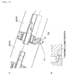
- first frame 31, a second frame 32, a third frame 33, a fourth frame 34 and a fifth frame 35 are connected in line along the same axis in the bending forceps 30 with the manipulator according to this embodiment.
- the first frame 31 and the second frame 32 are connected with the first frame pin 36 so as to constitute a first articulation portion 50.
- the second frame 32 and the third frame 33 are connected with the second frame pin 37 so as to constitute a second articulation portion 51. Then, the first articulation portion 50 and the second articulation portion 51 are constructed to be bendable along the same plane.
- first articulation portion 50 is constructed to be bendable up to, for example, 45° and have the first flame pin 36 as a rotary shaft.
- the second articulation portion 51 is constructed to be bendable up to, for example, 45° in the same direction as the bending of the first articulation portion.
- the third frame 33 to the first frame 31 are constructed so as to be bendable up to, for example, 90° with the first articulation portion 50 and the second articulation portion 51. Further, because the first articulation portion 50 and the second articulation portion 51 constitute the multi-slider linkage mechanism, the bending action of the second articulation portion 51 is blocked from starting until the bending action of the first articulation portion 50 is ended.
- the third frame 33 and the fourth frame 34 at the rear end side are connected with the third frame pin 38.
- the fourth frame 34 and the fifth frame 35 are connected with the guide pin 39.
- the third frame 33, the fourth frame 34 and the fifth frame 35 are constructed to be bendable in a direction along the same plane at each coupling portion with the third frame pin 38 and the guide pin 39 used as a rotary shaft.
- the third frame 33 to the fifth frame 35 are also constituted of multi-slider linkage mechanism having the first articulation portion 50 and the second articulation portion 51 like the first frame 31 to the third frame 33.
- the bending direction of the multi-slider linkage mechanism comprised of the third frame 33 to the fifth frame 35 and the bending direction of the multi-slider linkage mechanism comprised of the first frame 31 to the third frame 33 are constructed to be perpendicular to each other.
- the degree of freedom in bending action is intensified by combining bending along a predetermined face at the front end of the bending forceps portion 30 with bending along a plane perpendicular to that plane.
- the bending action of the second articulation portion 51 is not started until the bending action of the first articulation portion 50 is completed and the bending direction of the first articulation portion 50 is equal to the bending direction of the second articulation portion 51.
- the bending forceps 30 receives its own weight and other external force from outside, sometimes the second articulation portion 51 is bent before the bending action of the first articulation portion 50 is ended and the second articulation portion 51 is bent slightly in an opposite direction to its original bending direction corresponding to the bending action of the first articulation portion 50.
- lubricant cannot be used at a movable portion of the first articulation portion 50 or the second articulation portion 51 if the manipulator of this embodiment is used for minimally invasive surgery and thus, non-lubrication action needs to be executed.
- FIG. 5A shows the second articulation portion 51
- FIG. 5B shows a partial sectional view taken along the line B-B of the joint portion 51a of the second articulation portion 51.
- a connecting end of each of the second frame 32 and the third frame 33 is formed into a ring shape and they are jointed with the second frame pin 37 so as to constitute the joint portion 51a.
- the ring-like portion in which the second frame 32 and the third frame 33 are jointed with the second frame pin 37 is constructed in a tapered configuration at this joint portion 51a.
- the inner contact face of the joint portion 51a with the third frame 33 in the second frame 32 is formed in forward taper whose thickness increases as it reaches its root and the outer contact face in contact with the joint portion 51a of the third frame 33 is formed in the forward taper so as to follow up the forward taper at the joint portion 51a of the second frame 32 when they are not bent.
- the second articulation portion 51 is bent with the second frame pin 37 as a shaft at the joint portion 51a in which the two frames are formed in the forward taper, thicker portions in the forward tapered shape of the second frame 32 and the third frame 33 overlap each other accompanied by the advancement of the bending action.
- the dynamic energy acts so that its magnitude minimizes.
- a moment is applied to the joint portion 51a in the direction of minimizing the interacting force when the second articulation portion 51 is bent and accordingly, the magnitude of a moment required for the bending action of the second articulation portion 51 increases as compared with the magnitude of a moment for bending the first articulation portion 50.
- the front end of the bending forceps portion 30 has a movable forceps 40 which is opened at an angle of, for example, 60° and capable of gripping a solid object of a predetermined size which can be opened or closed.
- This movable forceps 40 comprises a fixed gripping tooth 40a and a movable gripping tooth 40b.
- the fixed gripping tooth 40a is fixed to the front end side of the first frame 31.
- the movable gripping tooth 40b is capable of being opened up to a predetermined angle ⁇ (for example, about 60°) and closed with an elastic body such as a spring (not shown) and by operation through one link member (for example, link member 23c) of the above-described three link members 23.
- the manipulator of this embodiment is constituted in the above-described way.
- the present invention can be applied to not only the manipulator but also any apparatus which operates by inserting its front end portion into a high pressure portion and transmitting a drive power through link members, the front end portion being provided with a movable portion, in an area having a higher internal pressure than the atmospheric pressure.
- the present invention can be applied to not only the manipulator but also any apparatuses having the multi-slider linkage mechanism.
- FIG. 1 is a sectional view showing a manipulator according to an embodiment of the present invention, a side view showing an outer case and a sectional view showing its front end portion.
- FIG. 2 is a perspective view showing a joint arm in the manipulator according to the embodiment of the present invention, a perspective view showing a connecting pin for connecting, and a sectional view showing a positional relation between the actuator portion and the joint portion at the time of joint and separation.
- FIG. 3 FIG. 3 is a perspective view showing a method for joining the actuator portion and the joint portion in the manipulator according to the embodiment of the present invention.
- FIG. 4 FIG.
- FIG. 4 is a perspective sectional view showing a link guide portion in the frame of the manipulator according to the embodiment of the present invention.
- FIG. 5 is a perspective view showing a second articulation portion equipped in the manipulator according to the embodiment of the present invention and a sectional view showing a joint portion.
- FIG. 6 is a diagram for explaining the multi-slider linkage mechanism of a related art.
- FIG. 7 is a diagram for explaining hang-up phenomenon (scuffing phenomenon) in the multi-slider linkage mechanism of the related art.
Landscapes
- Health & Medical Sciences (AREA)
- Surgery (AREA)
- Life Sciences & Earth Sciences (AREA)
- Engineering & Computer Science (AREA)
- Medical Informatics (AREA)
- Biomedical Technology (AREA)
- Heart & Thoracic Surgery (AREA)
- Nuclear Medicine, Radiotherapy & Molecular Imaging (AREA)
- Molecular Biology (AREA)
- Animal Behavior & Ethology (AREA)
- General Health & Medical Sciences (AREA)
- Public Health (AREA)
- Veterinary Medicine (AREA)
- Robotics (AREA)
- Ophthalmology & Optometry (AREA)
- Surgical Instruments (AREA)
- Manipulator (AREA)
Applications Claiming Priority (4)
| Application Number | Priority Date | Filing Date | Title |
|---|---|---|---|
| JP2003413721A JP4504000B2 (ja) | 2003-12-11 | 2003-12-11 | 屈曲動作部材、アクチュエータおよびマニピュレータ |
| JP2003413720A JP4524096B2 (ja) | 2003-12-11 | 2003-12-11 | 多節スライダ・リンク機構、屈曲動作部材およびマニピュレータ |
| JP2003413719A JP2005168846A (ja) | 2003-12-11 | 2003-12-11 | 屈曲動作部材およびマニピュレータ |
| PCT/JP2004/018598 WO2005055850A1 (fr) | 2003-12-11 | 2004-12-13 | Element de flexion, mecanisme a joint coulissant multiarticule, actionneur et manipulateur |
Publications (2)
| Publication Number | Publication Date |
|---|---|
| EP1693018A1 true EP1693018A1 (fr) | 2006-08-23 |
| EP1693018A4 EP1693018A4 (fr) | 2012-08-08 |
Family
ID=34681967
Family Applications (1)
| Application Number | Title | Priority Date | Filing Date |
|---|---|---|---|
| EP04806959A Withdrawn EP1693018A4 (fr) | 2003-12-11 | 2004-12-13 | Element de flexion, mecanisme a joint coulissant multiarticule, actionneur et manipulateur |
Country Status (3)
| Country | Link |
|---|---|
| US (1) | US20070219581A1 (fr) |
| EP (1) | EP1693018A4 (fr) |
| WO (1) | WO2005055850A1 (fr) |
Cited By (4)
| Publication number | Priority date | Publication date | Assignee | Title |
|---|---|---|---|---|
| EP2095778A1 (fr) * | 2008-02-26 | 2009-09-02 | Terumo Kabushiki Kaisha | Manipulateur |
| EP3192455A1 (fr) * | 2016-01-15 | 2017-07-19 | Covidien LP | Mécanisme de centrage pour articulation |
| EP3241501A4 (fr) * | 2014-12-30 | 2017-12-20 | Suzhou Touchstone International Medical Science Co., Ltd. | Appareil de suture et de coupe pour chirurgie endoscopique |
| CN111513775A (zh) * | 2015-04-10 | 2020-08-11 | 柯惠Lp公司 | 接合器组件和机电手术系统 |
Families Citing this family (12)
| Publication number | Priority date | Publication date | Assignee | Title |
|---|---|---|---|---|
| US20070219550A1 (en) * | 2006-01-27 | 2007-09-20 | Mark Thompson | Device and system for surgical dissection and/or guidance of other medical devices into body |
| BRPI0822560A8 (pt) * | 2008-04-18 | 2016-01-19 | Fortimedix B V | Instrumento para aplicações endoscópicas ou semelhantes |
| FR2943907B1 (fr) | 2009-04-03 | 2012-08-03 | Univ Pierre Et Marie Curie Paris 6 | Instrument chirurgical. |
| FR2943906B1 (fr) | 2009-04-03 | 2013-03-22 | Univ Pierre Et Marie Curie Paris 6 | Instrument chirurgical. |
| JP4862105B2 (ja) * | 2009-12-10 | 2012-01-25 | オリンパスメディカルシステムズ株式会社 | 医療用マニピュレータ |
| US9402682B2 (en) | 2010-09-24 | 2016-08-02 | Ethicon Endo-Surgery, Llc | Articulation joint features for articulating surgical device |
| US9144370B2 (en) | 2013-02-28 | 2015-09-29 | Canon Usa Inc. | Mechanical structure of articulated sheath |
| JP6506295B2 (ja) | 2013-09-20 | 2019-04-24 | ザ ブリガム アンド ウィメンズ ホスピタル インコーポレイテッドThe Brigham and Women’s Hospital, Inc. | 制御装置、及び腱駆動装置 |
| WO2017066253A1 (fr) | 2015-10-15 | 2017-04-20 | Canon U.S.A., Inc. | Instrument médical orientable |
| US11278366B2 (en) | 2017-04-27 | 2022-03-22 | Canon U.S.A., Inc. | Method for controlling a flexible manipulator |
| US11007641B2 (en) | 2017-07-17 | 2021-05-18 | Canon U.S.A., Inc. | Continuum robot control methods and apparatus |
| WO2019050797A1 (fr) * | 2017-09-05 | 2019-03-14 | Intuitive Surgical Operations, Inc. | Systèmes et procédés de chirurgie télécommandée assistée par ordinateur |
Family Cites Families (12)
| Publication number | Priority date | Publication date | Assignee | Title |
|---|---|---|---|---|
| US5235966A (en) * | 1991-10-17 | 1993-08-17 | Jay Jamner | Endoscopic retractor |
| JPH05199981A (ja) * | 1992-01-24 | 1993-08-10 | Olympus Optical Co Ltd | 内視鏡 |
| US5425737A (en) * | 1992-04-08 | 1995-06-20 | American Cyanamid Co. | Surgical purse string suturing instrument and method |
| US5540706A (en) * | 1993-01-25 | 1996-07-30 | Aust; Gilbert M. | Surgical instrument |
| US5441494A (en) * | 1993-07-29 | 1995-08-15 | Ethicon, Inc. | Manipulable hand for laparoscopy |
| US5614153A (en) * | 1995-05-26 | 1997-03-25 | Rainin Instrument Co., Inc. | Pipette tip ejector |
| JP3704399B2 (ja) * | 1996-06-21 | 2005-10-12 | オリンパス株式会社 | 超音波処置具 |
| US5928136A (en) * | 1997-02-13 | 1999-07-27 | Karl Storz Gmbh & Co. | Articulated vertebra for endoscopes and method to make it |
| US6077290A (en) * | 1999-09-10 | 2000-06-20 | Tnco, Incorporated | Endoscopic instrument with removable front end |
| US6743239B1 (en) * | 2000-05-25 | 2004-06-01 | St. Jude Medical, Inc. | Devices with a bendable tip for medical procedures |
| JP4370067B2 (ja) * | 2001-04-18 | 2009-11-25 | オリンパス株式会社 | 外科用処置具 |
| DE60218240T2 (de) * | 2001-04-18 | 2007-11-22 | Olympus Corporation | Chirurgisches Instrument |
-
2004
- 2004-12-13 EP EP04806959A patent/EP1693018A4/fr not_active Withdrawn
- 2004-12-13 US US10/582,354 patent/US20070219581A1/en not_active Abandoned
- 2004-12-13 WO PCT/JP2004/018598 patent/WO2005055850A1/fr not_active Ceased
Cited By (11)
| Publication number | Priority date | Publication date | Assignee | Title |
|---|---|---|---|---|
| EP2095778A1 (fr) * | 2008-02-26 | 2009-09-02 | Terumo Kabushiki Kaisha | Manipulateur |
| US8382790B2 (en) | 2008-02-26 | 2013-02-26 | Terumo Kabushiki Kaisha | Manipulator |
| EP3241501A4 (fr) * | 2014-12-30 | 2017-12-20 | Suzhou Touchstone International Medical Science Co., Ltd. | Appareil de suture et de coupe pour chirurgie endoscopique |
| US10603063B2 (en) | 2014-12-30 | 2020-03-31 | Suzhou Touchstone International Medical Science Co., Ltd. | Suturing and cutting apparatus for endoscopic surgery |
| CN111513775A (zh) * | 2015-04-10 | 2020-08-11 | 柯惠Lp公司 | 接合器组件和机电手术系统 |
| CN111513775B (zh) * | 2015-04-10 | 2024-01-02 | 柯惠Lp公司 | 接合器组件和机电手术系统 |
| US11877733B2 (en) | 2015-04-10 | 2024-01-23 | Covidien Lp | Adapter assembly with gimbal for interconnecting electromechanical surgical devices and surgical loading units, and surgical systems thereof |
| EP3192455A1 (fr) * | 2016-01-15 | 2017-07-19 | Covidien LP | Mécanisme de centrage pour articulation |
| CN107019536A (zh) * | 2016-01-15 | 2017-08-08 | 柯惠Lp公司 | 用于关节式运动关节的定心机构 |
| US10660623B2 (en) | 2016-01-15 | 2020-05-26 | Covidien Lp | Centering mechanism for articulation joint |
| CN107019536B (zh) * | 2016-01-15 | 2021-10-08 | 柯惠Lp公司 | 用于关节式运动关节的定心机构 |
Also Published As
| Publication number | Publication date |
|---|---|
| US20070219581A1 (en) | 2007-09-20 |
| EP1693018A4 (fr) | 2012-08-08 |
| WO2005055850A1 (fr) | 2005-06-23 |
Similar Documents
| Publication | Publication Date | Title |
|---|---|---|
| EP1693018A1 (fr) | Element de flexion, mecanisme a joint coulissant multiarticule, actionneur et manipulateur | |
| JP6989594B2 (ja) | 手首構造 | |
| CN102470003B (zh) | 医疗用机械手 | |
| JP6312907B2 (ja) | 冗長な閉鎖機構を有するエンドエフェクタ | |
| US6206903B1 (en) | Surgical tool with mechanical advantage | |
| US20180028210A1 (en) | Laparoscopic Instrument with Attachable End Effector | |
| US20070238925A1 (en) | Surgical instrument coupling mechanism | |
| US10342520B2 (en) | Articulating surgical devices and loaders having stabilizing features | |
| US20120078290A1 (en) | Laparoscopic instrument with attachable end effector | |
| CN103917180A (zh) | 具有包含球形部件的关节部的微创手术器械 | |
| WO2012040183A1 (fr) | Instrument laparoscopique équipé d'un organe effecteur amovible | |
| US20220202402A1 (en) | Control mechanism for end effectors and method of use | |
| JP2009247904A (ja) | マルチフラッパー設計を有するアクセスアセンブリ | |
| CN113811251A (zh) | 微创手术器械 | |
| KR20190096544A (ko) | 복강경 수술장치 | |
| JP2020116282A (ja) | 手術器具 | |
| US11759223B2 (en) | Articulation locking mechanisms for end effectors and methods of use | |
| US10363035B2 (en) | Stapler tool with rotary drive lockout | |
| JP7502580B2 (ja) | 低侵襲性手術機器 | |
| CN223111761U (zh) | 一种应用在胸腔镜手术中的多自由度手术器械 | |
| JP4504000B2 (ja) | 屈曲動作部材、アクチュエータおよびマニピュレータ | |
| JP4524096B2 (ja) | 多節スライダ・リンク機構、屈曲動作部材およびマニピュレータ | |
| JP2005168846A (ja) | 屈曲動作部材およびマニピュレータ | |
| CN118303953B (zh) | 一种手持手枪形多角度可弯曲手术器械 | |
| US12514572B2 (en) | Separable surgical instrument joints |
Legal Events
| Date | Code | Title | Description |
|---|---|---|---|
| PUAI | Public reference made under article 153(3) epc to a published international application that has entered the european phase |
Free format text: ORIGINAL CODE: 0009012 |
|
| 17P | Request for examination filed |
Effective date: 20060613 |
|
| AK | Designated contracting states |
Kind code of ref document: A1 Designated state(s): DE GB |
|
| RIN1 | Information on inventor provided before grant (corrected) |
Inventor name: IIMURA, AKIHIRO,C/O THK CO., LTD. Inventor name: YAMASHITA, HIROMASA Inventor name: HATA, NOBUHIKOL1-050 DPMT OF RADIOLOGY Inventor name: NAKAZAWA, TOJI,C/O THK CO., LTD. Inventor name: DOHI, TAKEYOSHI |
|
| DAX | Request for extension of the european patent (deleted) | ||
| RBV | Designated contracting states (corrected) |
Designated state(s): DE GB |
|
| RIN1 | Information on inventor provided before grant (corrected) |
Inventor name: DOHI, TAKEYOSHI Inventor name: NAKAZAWA, TOJI,C/O THK CO., LTD. Inventor name: HATA, NOBUHIKOL1-050 DPMT OF RADIOLOGY Inventor name: YAMASHITA, HIROMASA Inventor name: IIMURA, AKIHIRO,C/O THK CO., LTD. |
|
| RAP1 | Party data changed (applicant data changed or rights of an application transferred) |
Owner name: DOHI, TAKEYOSHI |
|
| A4 | Supplementary search report drawn up and despatched |
Effective date: 20120711 |
|
| RIC1 | Information provided on ipc code assigned before grant |
Ipc: A61B 17/28 20060101AFI20120705BHEP |
|
| 17Q | First examination report despatched |
Effective date: 20121214 |
|
| STAA | Information on the status of an ep patent application or granted ep patent |
Free format text: STATUS: THE APPLICATION IS DEEMED TO BE WITHDRAWN |
|
| 18D | Application deemed to be withdrawn |
Effective date: 20130425 |