EP1693141A2 - Dispositif et procédé de mesure localisée de température au cours d'un procédé de traitement laser - Google Patents
Dispositif et procédé de mesure localisée de température au cours d'un procédé de traitement laser Download PDFInfo
- Publication number
- EP1693141A2 EP1693141A2 EP05022780A EP05022780A EP1693141A2 EP 1693141 A2 EP1693141 A2 EP 1693141A2 EP 05022780 A EP05022780 A EP 05022780A EP 05022780 A EP05022780 A EP 05022780A EP 1693141 A2 EP1693141 A2 EP 1693141A2
- Authority
- EP
- European Patent Office
- Prior art keywords
- arrangement according
- processing area
- electromagnetic radiation
- optical detector
- determined
- Prior art date
- Legal status (The legal status is an assumption and is not a legal conclusion. Google has not performed a legal analysis and makes no representation as to the accuracy of the status listed.)
- Granted
Links
Images

Classifications
-
- B—PERFORMING OPERATIONS; TRANSPORTING
- B23—MACHINE TOOLS; METAL-WORKING NOT OTHERWISE PROVIDED FOR
- B23K—SOLDERING OR UNSOLDERING; WELDING; CLADDING OR PLATING BY SOLDERING OR WELDING; CUTTING BY APPLYING HEAT LOCALLY, e.g. FLAME CUTTING; WORKING BY LASER BEAM
- B23K26/00—Working by laser beam, e.g. welding, cutting or boring
- B23K26/02—Positioning or observing the workpiece, e.g. with respect to the point of impact; Aligning, aiming or focusing the laser beam
- B23K26/03—Observing, e.g. monitoring, the workpiece
- B23K26/032—Observing, e.g. monitoring, the workpiece using optical means
-
- B—PERFORMING OPERATIONS; TRANSPORTING
- B23—MACHINE TOOLS; METAL-WORKING NOT OTHERWISE PROVIDED FOR
- B23K—SOLDERING OR UNSOLDERING; WELDING; CLADDING OR PLATING BY SOLDERING OR WELDING; CUTTING BY APPLYING HEAT LOCALLY, e.g. FLAME CUTTING; WORKING BY LASER BEAM
- B23K26/00—Working by laser beam, e.g. welding, cutting or boring
- B23K26/02—Positioning or observing the workpiece, e.g. with respect to the point of impact; Aligning, aiming or focusing the laser beam
- B23K26/03—Observing, e.g. monitoring, the workpiece
- B23K26/034—Observing the temperature of the workpiece
-
- B—PERFORMING OPERATIONS; TRANSPORTING
- B23—MACHINE TOOLS; METAL-WORKING NOT OTHERWISE PROVIDED FOR
- B23K—SOLDERING OR UNSOLDERING; WELDING; CLADDING OR PLATING BY SOLDERING OR WELDING; CUTTING BY APPLYING HEAT LOCALLY, e.g. FLAME CUTTING; WORKING BY LASER BEAM
- B23K26/00—Working by laser beam, e.g. welding, cutting or boring
- B23K26/02—Positioning or observing the workpiece, e.g. with respect to the point of impact; Aligning, aiming or focusing the laser beam
- B23K26/03—Observing, e.g. monitoring, the workpiece
- B23K26/0342—Observing magnetic fields related to the workpiece
Definitions
- the invention relates to an arrangement and a method for spatially resolved temperature measurement in a laser processing method. It can be used in a variety of laser processing methods, such as laser beam curing, laser beam welding and laser beam deposition welding and laser cutting.
- the temperatures at the different positions of a respective machining area are dependent on a number of parameters, such as the respective power used during machining, the deflection speed and / or direction of laser working beams and the workpiece to be machined, both temporally and locally change, a spatially resolved determination of temperatures within a processing area is desired.
- EP 0 904 886 A1 discloses a method for detecting and tracking the geometry in the thermal processing of components by means of laser radiation.
- a component in the process heat recorded temperature field via a photothermal sensor system in its two-dimensional projection.
- an arrangement with a bandpass filter, a diaphragm and a lens is used to focus temperature radiation on a pinhole, which is followed by an infrared detector.
- the lens and aperture are to be moved back and forth in the beam direction or perpendicular to this, so that the infrared detector in the respective points of impact of the working laser beam spot can measure the temperature directly.
- Such a measuring structure is elaborately constructed and it must also be operated in a controlled manner, so that in each case an adaptation to the respective machining process and the workpiece to be machined must be carried out.
- the arrangement according to the invention is designed such that a prescribable processing region of a workpiece is imaged on a spatially resolved optical detector.
- at least one electromagnetic filter blocking the electromagnetic radiation of one or more laser working beams / beams is arranged in the beam path of electromagnetic radiation emitted by the predeterminable processing region between the respective processing region and the optical detector.
- the predeterminable processing area to be imaged on the optical detector can be adapted with respect to its geometric edge contour and size to the respective laser processing method and optionally also during the processing parameters to be maintained.
- spatially resolved measuring optical detectors for example, CCD arrays or CMOS arrays, but preferably CCD cameras can be used.
- Particularly preferred in such spatially resolved optical detectors is an increased sensitivity in the range of the electromagnetic radiation of the visible, the near infrared and optionally also the infrared light.
- the at least one optical filter should be selected so that it for electromagnetic radiation with a smaller wavelength than the wavelength of the electromagnetic radiation of a laser working beam or be multiple laser working beams. In the event that several laser working beams have been used by different laser radiation sources, the respective optical filter should then be selected for electromagnetic radiation with a smaller wavelength than that of the electromagnetic radiation of the laser working beam also with a smaller wavelength.
- edge filters can also be used as optical filters, which are then preferably transparent for wavelengths smaller than those of the laser working beams.
- a quasi "bandpass filter” can also be formed in the wavelength range between the two correspondingly oppositely formed edge filters, ie between a minimum and a maximum wavelength of the respective two edge filters.
- the respective wavelength interval in which transparency for the electromagnetic radiation emitted by the processing area is transparent has a maximum bandwidth of 50 nm, preferably not more than 20 nm and more preferably not more than 10 nm.
- an optical filter can be selected which is transparent only for a single wavelength can be used.
- optical filter which is transparent below 850 nm.
- the arrangement according to the invention can advantageously be designed such that the sensitive elements of the respective optical detector, for example the individual pixels of a CCD camera, are connected to an electronic evaluation unit, with which a further processing of the individual temperature values determined with the sensitive elements is possible.
- a control unit can be integrated in the addressed electronic evaluation unit or also connected to this evaluation unit.
- the control can be in a wide variety of forms, but preferably a power control of the laser working beams.
- the pulse frequency, the power density in the focal spot can be effected by appropriate beam shaping and / or the deflection speed / direction of laser working beams.
- an intensity of individual position coordinates of the processing region of emitted electromagnetic radiation is respectively detected with the individual sensitive elements of the optical detector and determined as a measure of the respective temperature.
- the determination of a maximum temperature in the processing area can be carried out and this can certainly provide sufficient information.
- the evaluation can also take the form that for certain temperatures, which may also apply to temperature intervals, their distribution or a corresponding determination of the center of gravity of temperatures can be determined.
- an evaluation of the spatially resolved specific temperatures can also be carried out in such a way that measured values acquired with sensitive elements are evaluated which exceed a predetermined threshold value and thus further statements regarding the heating of the workpiece within the processing area can be obtained by the laser processing.
- the respective size, the position and / or geometric shape of one or more surface (s) of the processing area with temperatures exceeding a predetermined maximum temperature can be determined, whereby further knowledge for the current processing of the workpiece can be obtained which can then be used again for the regulation of the process.
- changing sizes, positions and / or geometrical shapes of such areas in which the predetermined maximum temperature has been exceeded are determined and then optionally obtained statements about the thermal conductivity of the workpiece at the respective position to be machined.
- a so-called “black body” can preferably be used.
- the one or more optical filters interchangeable, so that one or more optical / optical filters can be used for the respective application whose transparency, the respective emitted from the processing area electromagnetic radiation and the wavelength (s) of one or more laser working beam (s) can be considered.
- such an optical filter can additionally be arranged in the corresponding beam path such that electromagnetic radiation blocks a characteristic spectral line of a chemical element occurring in / on the material of a workpiece to be machined, so that this electromagnetic radiation can not cause a measurement error in the spatially resolved temperature determination.
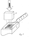
- FIG. 1 shows an example of an arrangement according to the invention, in which a laser working beam 1 is directed onto the surface of a workpiece 4 via a beam shaping unit 6.
- a rectangular focal spot was formed with the beam shaping unit 6 in this case.
- a predetermined processing area 5 on the surface to be processed of the workpiece 4 is then imaged onto a spatially resolved optical detector 2, in front of which an optical filter 3 is arranged, which is for electromagnetic radiation in the wavelength range below the respective wavelength of the electromagnetic radiation of the laser working beam. 1 lies, is transparent.
- focal spot geometries focal spot dimensions and then also corresponding geometries and area sizes of the respective imaged processing area 5 are possible in laser processing.
- a laser working beam 1 which has electromagnetic radiation with a wavelength of 940 nm.
- the employed optical filter 3 is transparent only in the wavelength range between 730 and 750 nm.
- FIG. 2 differs from the example according to FIG. 1 only in that a beam splitter 7 is additionally arranged in the beam path of the laser working beam 1, via which the electromagnetic radiation emitted by the processing area 5 is deflected orthogonally and thus the processing area 5 after the deflection by the beam splitter 7 on the spatially resolved measuring optical detector 2, after passing through the optical filter 3, is mapped.
- a beam splitter 7 is additionally arranged in the beam path of the laser working beam 1, via which the electromagnetic radiation emitted by the processing area 5 is deflected orthogonally and thus the processing area 5 after the deflection by the beam splitter 7 on the spatially resolved measuring optical detector 2, after passing through the optical filter 3, is mapped.
- the individual intensities depending on the local resolution of the spatially resolved measuring optical detector 2 with its respective sensitive elements determined and used as a measure of the respective locally differentiated temperature readings, evaluated according to the comments in the general part of the description and optionally for the Regulation of the respective laser processing process used.
Landscapes
- Physics & Mathematics (AREA)
- Optics & Photonics (AREA)
- Engineering & Computer Science (AREA)
- Plasma & Fusion (AREA)
- Mechanical Engineering (AREA)
- Radiation Pyrometers (AREA)
- Laser Beam Processing (AREA)
- Recrystallisation Techniques (AREA)
- Photometry And Measurement Of Optical Pulse Characteristics (AREA)
Applications Claiming Priority (1)
| Application Number | Priority Date | Filing Date | Title |
|---|---|---|---|
| DE102004051876A DE102004051876A1 (de) | 2004-10-20 | 2004-10-20 | Anordnung und Verfahren zur ortsaufgelösten Temperaturmessung bei einem Laserbearbeitungsverfahren |
Publications (3)
| Publication Number | Publication Date |
|---|---|
| EP1693141A2 true EP1693141A2 (fr) | 2006-08-23 |
| EP1693141A3 EP1693141A3 (fr) | 2008-07-30 |
| EP1693141B1 EP1693141B1 (fr) | 2011-07-06 |
Family
ID=35589326
Family Applications (1)
| Application Number | Title | Priority Date | Filing Date |
|---|---|---|---|
| EP05022780A Expired - Lifetime EP1693141B1 (fr) | 2004-10-20 | 2005-10-19 | Dispositif et procédé de mesure localisée de température au cours d'un procédé de traitement laser |
Country Status (3)
| Country | Link |
|---|---|
| EP (1) | EP1693141B1 (fr) |
| AT (1) | ATE515358T1 (fr) |
| DE (1) | DE102004051876A1 (fr) |
Cited By (10)
| Publication number | Priority date | Publication date | Assignee | Title |
|---|---|---|---|---|
| US9089926B2 (en) | 2006-11-04 | 2015-07-28 | Trumpf Werkzeugmaschinen Gmbh + Co. Kg | Process monitoring the processing of a material |
| US9289852B2 (en) | 2011-01-27 | 2016-03-22 | Bystronic Laser Ag | Laser processing machine, laser cutting machine, and method for adjusting a focused laser beam |
| US9296067B2 (en) | 2011-01-27 | 2016-03-29 | Bystronic Laser Ag | Laser processing machine, in particular laser cutting machine, and method for centering a laser beam, in particular a focused laser beam |
| US9573224B2 (en) | 2014-09-02 | 2017-02-21 | Product Innovation & Engineering, LLC | System and method for determining beam power level along an additive deposition path |
| US9757902B2 (en) | 2014-09-02 | 2017-09-12 | Product Innovation and Engineering L.L.C. | Additive layering method using improved build description |
| US9839975B2 (en) | 2013-12-12 | 2017-12-12 | Bystronic Laser Ag | Method for configuring a laser machining machine |
| US9937590B2 (en) | 2010-07-22 | 2018-04-10 | Bystronic Laser Ag | Laser processing machine |
| US10632566B2 (en) | 2014-12-02 | 2020-04-28 | Product Innovation and Engineering L.L.C. | System and method for controlling the input energy from an energy point source during metal processing |
| CN112074361A (zh) * | 2018-02-13 | 2020-12-11 | 弗劳恩霍夫应用研究促进协会 | 用于相对于能量束的中心纵轴调节粉末流的装置 |
| US11839915B2 (en) | 2021-01-20 | 2023-12-12 | Product Innovation and Engineering LLC | System and method for determining beam power level along an additive deposition path |
Families Citing this family (6)
| Publication number | Priority date | Publication date | Assignee | Title |
|---|---|---|---|---|
| DE102007024510B3 (de) * | 2007-05-24 | 2008-09-11 | Jenoptik Automatisierungstechnik Gmbh | Verfahren und Vorrichtung zur Herstellung einer Sollbruchlinie in ein Fahrzeuginnenverkleidungsteil |
| DE102008016019A1 (de) * | 2008-03-25 | 2009-10-01 | Jenoptik Automatisierungstechnik Gmbh | Verfahren zur Qualitätsprüfung einer Schweißnaht von im Überlappstoß geschweißten Kunststoffbauteilen |
| DE102010011253B4 (de) * | 2010-03-12 | 2013-07-11 | Precitec Kg | Laserbearbeitungskopf, Robotervorrichtung und Verfahren zur Bearbeitung eines Werkstücks mittels eines Laserstrahls |
| DE102016211935B4 (de) | 2016-06-30 | 2019-06-06 | Sauer Gmbh | Vorrichtung und Verfahren zur Prozessüberwachung bei einem Auftragschweiß-Verfahren |
| DE102019206179B4 (de) * | 2019-04-30 | 2023-06-07 | Fraunhofer-Gesellschaft zur Förderung der angewandten Forschung e.V. | Anordnung zur Modifizierung von Oberflächen metallischer Bauteile |
| EP4173741A1 (fr) | 2021-10-28 | 2023-05-03 | Fraunhofer-Gesellschaft zur Förderung der angewandten Forschung e.V. | Procédé et dispositif de surveillance d'un processus d'usinage laser par photométrie de speckle |
Citations (3)
| Publication number | Priority date | Publication date | Assignee | Title |
|---|---|---|---|---|
| US5382770A (en) | 1993-01-14 | 1995-01-17 | Reliant Laser Corporation | Mirror-based laser-processing system with visual tracking and position control of a moving laser spot |
| US5659479A (en) | 1993-10-22 | 1997-08-19 | Powerlasers Ltd. | Method and apparatus for real-time control of laser processing of materials |
| EP0904886A1 (fr) | 1997-09-20 | 1999-03-31 | INPRO Innovationsgesellschaft für fortgeschrittene Produktionssysteme in der Fahrzeugindustrie mbH | Procédé de reconnnaissance de géométrie et de suivi au cours de traitement thermique d'éléments au moyen de faisceau laser |
Family Cites Families (4)
| Publication number | Priority date | Publication date | Assignee | Title |
|---|---|---|---|---|
| DE19716293C2 (de) * | 1997-04-18 | 2000-07-13 | Daimler Chrysler Ag | Vorrichtung zur Regelung der Fokuslage beim Laserstrahlschweißen |
| DE19927803A1 (de) * | 1999-06-11 | 2000-12-28 | Matthias Negendanck | Vorrichtung zur Kontrolle der Fokuslage beim Laserstrahlschweißen |
| DE10225450C5 (de) * | 2002-06-08 | 2014-07-31 | Robert Bosch Gmbh | Verfahren zur Fehlerdetektion bei Laserbearbeitungsprozessen |
| DE10243411B4 (de) * | 2002-09-18 | 2004-07-08 | Deutsches Zentrum für Luft- und Raumfahrt e.V. | Verfahren zur Kalibrierung von Messgeräten zur quantitativen Infrarotstrahlungsmessung |
-
2004
- 2004-10-20 DE DE102004051876A patent/DE102004051876A1/de not_active Ceased
-
2005
- 2005-10-19 EP EP05022780A patent/EP1693141B1/fr not_active Expired - Lifetime
- 2005-10-19 AT AT05022780T patent/ATE515358T1/de active
Patent Citations (3)
| Publication number | Priority date | Publication date | Assignee | Title |
|---|---|---|---|---|
| US5382770A (en) | 1993-01-14 | 1995-01-17 | Reliant Laser Corporation | Mirror-based laser-processing system with visual tracking and position control of a moving laser spot |
| US5659479A (en) | 1993-10-22 | 1997-08-19 | Powerlasers Ltd. | Method and apparatus for real-time control of laser processing of materials |
| EP0904886A1 (fr) | 1997-09-20 | 1999-03-31 | INPRO Innovationsgesellschaft für fortgeschrittene Produktionssysteme in der Fahrzeugindustrie mbH | Procédé de reconnnaissance de géométrie et de suivi au cours de traitement thermique d'éléments au moyen de faisceau laser |
Cited By (12)
| Publication number | Priority date | Publication date | Assignee | Title |
|---|---|---|---|---|
| US9089926B2 (en) | 2006-11-04 | 2015-07-28 | Trumpf Werkzeugmaschinen Gmbh + Co. Kg | Process monitoring the processing of a material |
| US9937590B2 (en) | 2010-07-22 | 2018-04-10 | Bystronic Laser Ag | Laser processing machine |
| US9289852B2 (en) | 2011-01-27 | 2016-03-22 | Bystronic Laser Ag | Laser processing machine, laser cutting machine, and method for adjusting a focused laser beam |
| US9296067B2 (en) | 2011-01-27 | 2016-03-29 | Bystronic Laser Ag | Laser processing machine, in particular laser cutting machine, and method for centering a laser beam, in particular a focused laser beam |
| US9839975B2 (en) | 2013-12-12 | 2017-12-12 | Bystronic Laser Ag | Method for configuring a laser machining machine |
| US9573224B2 (en) | 2014-09-02 | 2017-02-21 | Product Innovation & Engineering, LLC | System and method for determining beam power level along an additive deposition path |
| US9757902B2 (en) | 2014-09-02 | 2017-09-12 | Product Innovation and Engineering L.L.C. | Additive layering method using improved build description |
| US10632566B2 (en) | 2014-12-02 | 2020-04-28 | Product Innovation and Engineering L.L.C. | System and method for controlling the input energy from an energy point source during metal processing |
| CN112074361A (zh) * | 2018-02-13 | 2020-12-11 | 弗劳恩霍夫应用研究促进协会 | 用于相对于能量束的中心纵轴调节粉末流的装置 |
| CN112074361B (zh) * | 2018-02-13 | 2023-03-28 | 弗劳恩霍夫应用研究促进协会 | 用于相对于能量束的中心纵轴调节粉末流的装置 |
| US11890675B2 (en) | 2018-02-13 | 2024-02-06 | Fraunhofer-Gesellschaft Zur Foerderung Der Angewandten Forschung E.V. | Arrangement for adjusting a powder flow in relation to the central longitudinal |
| US11839915B2 (en) | 2021-01-20 | 2023-12-12 | Product Innovation and Engineering LLC | System and method for determining beam power level along an additive deposition path |
Also Published As
| Publication number | Publication date |
|---|---|
| ATE515358T1 (de) | 2011-07-15 |
| EP1693141B1 (fr) | 2011-07-06 |
| DE102004051876A1 (de) | 2006-04-27 |
| EP1693141A3 (fr) | 2008-07-30 |
Similar Documents
| Publication | Publication Date | Title |
|---|---|---|
| EP1693141B1 (fr) | Dispositif et procédé de mesure localisée de température au cours d'un procédé de traitement laser | |
| EP2094429B9 (fr) | Procédé et dispositif de surveillance de processus lors de l'usinage de matériaux | |
| DE102016123000B3 (de) | Verfahren zur Überwachung eines Schutzglases und Überwachungsvorrichtung | |
| EP2726244B1 (fr) | Procédé de détection de défauts sur une soudure non-linéaire ou une fente de coupe non-linéaire au cours d'un processus d'usinage par laser ; dispositif d'usinage par laser correspondant | |
| EP3003633B1 (fr) | Dispositif et procédé pour déterminer la position focale d'un faisceau d'énergie à haute densité | |
| EP3525975B1 (fr) | Procédé et dispositif pour la détermination et la régulation d'une position focale d'un faisceau d'usinage | |
| DE112018001597T5 (de) | Systeme und Verfahren zum Messen abgestrahlter thermischer Energie während der Ausführung einer additiven Fertigung | |
| DE102018102828B4 (de) | Verfahren zur Überwachung eines Schutzglases | |
| EP3102361B1 (fr) | Procédé pour identifier le contour de bord d'une ouverture formée sur une tête d'usinage et machine d'usinage associée | |
| DE102016001355A1 (de) | Analyse von Laserstrahlen in Anlagen für generative Fertigung | |
| EP1099506A1 (fr) | Méthode et dispositif de mesure de paramètres d'un procédé d'usinage de matériaux | |
| EP3911498B1 (fr) | Surveillance et régulation du processus d'une fabrication additive d'une pièce à usiner | |
| DE102018200566A1 (de) | System und Verfahren zur Überwachung der Fertigungsgenauigkeit bei der additiven Herstellung dreidimensionaler Bauteile | |
| DE102010015023A1 (de) | Verfahren und Vorrichtung zur Qualitätssicherung und Prozesskontrolle bei der Laserbearbeitung von Werkstücken | |
| DE102008036275B4 (de) | Verfahren zum Vermessen von Profilen mit optischen Sensoren | |
| DE2945251A1 (de) | Verfahren und vorrichtung zur bestimmung der lage einer oberflaeche | |
| DE4444079A1 (de) | Verfahren und Vorrichtung zur Durchführung dieses Verfahrens zum Messen einer Lage von Bahnen oder Bogen | |
| DE102014202977B4 (de) | Verfahren und Vorrichtung zur Bestimmung von Koordinaten eines Werkstücks unter Verwendung eines Koordinatenmessgeräts | |
| EP2618958B1 (fr) | Utilisation de la polarité d'une émission thermique pour la détection d'une surface tri-dimensionnelle. | |
| DE102021133930B3 (de) | Verfahren zur Bestimmung einer Temperaturverteilung in und/oder unmittelbar um ein Schmelzbad bei einem Laser- oder Elektronenstrahlschmelzen | |
| DE10056329B4 (de) | Optisches Abstandsmeßverfahren und Abstandssensor | |
| DE102012112412A1 (de) | Vorrichtung und Verfahren zur Messung einer ortsaufgelösten Temperaturverteilung | |
| DE102017102762B4 (de) | Verfahren zum Erkennen von Fügepositionen von Werkstücken und Laserbearbeitungskopf mit einer Vorrichtung zur Durchführung dieses Verfahrens | |
| DE102020201097B4 (de) | Anordnung und Verfahren zur optischen Objektkoordinatenermittlung | |
| EP1457286A2 (fr) | Procédé, dispositif de surveillance et leur utilisation et dispositif d'usinage laser avec surveillance de défaut d'un composant optique |
Legal Events
| Date | Code | Title | Description |
|---|---|---|---|
| PUAI | Public reference made under article 153(3) epc to a published international application that has entered the european phase |
Free format text: ORIGINAL CODE: 0009012 |
|
| AK | Designated contracting states |
Kind code of ref document: A2 Designated state(s): AT BE BG CH CY CZ DE DK EE ES FI FR GB GR HU IE IS IT LI LT LU LV MC NL PL PT RO SE SI SK TR |
|
| AX | Request for extension of the european patent |
Extension state: AL BA HR MK YU |
|
| RAP1 | Party data changed (applicant data changed or rights of an application transferred) |
Owner name: FRAUNHOFER-GESELLSCHAFT ZUR FOERDERUNG DER ANGEWAN |
|
| PUAL | Search report despatched |
Free format text: ORIGINAL CODE: 0009013 |
|
| AK | Designated contracting states |
Kind code of ref document: A3 Designated state(s): AT BE BG CH CY CZ DE DK EE ES FI FR GB GR HU IE IS IT LI LT LU LV MC NL PL PT RO SE SI SK TR |
|
| AX | Request for extension of the european patent |
Extension state: AL BA HR MK YU |
|
| 17P | Request for examination filed |
Effective date: 20081201 |
|
| AKX | Designation fees paid |
Designated state(s): AT BE BG CH CY CZ DE DK EE ES FI FR GB GR HU IE IS IT LI LT LU LV MC NL PL PT RO SE SI SK TR |
|
| 17Q | First examination report despatched |
Effective date: 20100810 |
|
| GRAP | Despatch of communication of intention to grant a patent |
Free format text: ORIGINAL CODE: EPIDOSNIGR1 |
|
| GRAS | Grant fee paid |
Free format text: ORIGINAL CODE: EPIDOSNIGR3 |
|
| GRAA | (expected) grant |
Free format text: ORIGINAL CODE: 0009210 |
|
| AK | Designated contracting states |
Kind code of ref document: B1 Designated state(s): AT BE BG CH CY CZ DE DK EE ES FI FR GB GR HU IE IS IT LI LT LU LV MC NL PL PT RO SE SI SK TR |
|
| REG | Reference to a national code |
Ref country code: GB Ref legal event code: FG4D Free format text: NOT ENGLISH |
|
| REG | Reference to a national code |
Ref country code: CH Ref legal event code: EP |
|
| REG | Reference to a national code |
Ref country code: IE Ref legal event code: FG4D Free format text: LANGUAGE OF EP DOCUMENT: GERMAN |
|
| REG | Reference to a national code |
Ref country code: CH Ref legal event code: NV Representative=s name: ROSENICH PAUL; GISLER CHRISTIAN PATENTBUERO PAUL R |
|
| REG | Reference to a national code |
Ref country code: DE Ref legal event code: R096 Ref document number: 502005011577 Country of ref document: DE Effective date: 20110901 |
|
| REG | Reference to a national code |
Ref country code: NL Ref legal event code: T3 |
|
| PG25 | Lapsed in a contracting state [announced via postgrant information from national office to epo] |
Ref country code: SI Free format text: LAPSE BECAUSE OF FAILURE TO SUBMIT A TRANSLATION OF THE DESCRIPTION OR TO PAY THE FEE WITHIN THE PRESCRIBED TIME-LIMIT Effective date: 20110706 |
|
| PG25 | Lapsed in a contracting state [announced via postgrant information from national office to epo] |
Ref country code: PT Free format text: LAPSE BECAUSE OF FAILURE TO SUBMIT A TRANSLATION OF THE DESCRIPTION OR TO PAY THE FEE WITHIN THE PRESCRIBED TIME-LIMIT Effective date: 20111107 Ref country code: FI Free format text: LAPSE BECAUSE OF FAILURE TO SUBMIT A TRANSLATION OF THE DESCRIPTION OR TO PAY THE FEE WITHIN THE PRESCRIBED TIME-LIMIT Effective date: 20110706 Ref country code: IS Free format text: LAPSE BECAUSE OF FAILURE TO SUBMIT A TRANSLATION OF THE DESCRIPTION OR TO PAY THE FEE WITHIN THE PRESCRIBED TIME-LIMIT Effective date: 20111106 Ref country code: SE Free format text: LAPSE BECAUSE OF FAILURE TO SUBMIT A TRANSLATION OF THE DESCRIPTION OR TO PAY THE FEE WITHIN THE PRESCRIBED TIME-LIMIT Effective date: 20110706 Ref country code: LT Free format text: LAPSE BECAUSE OF FAILURE TO SUBMIT A TRANSLATION OF THE DESCRIPTION OR TO PAY THE FEE WITHIN THE PRESCRIBED TIME-LIMIT Effective date: 20110706 |
|
| REG | Reference to a national code |
Ref country code: IE Ref legal event code: FD4D |
|
| PG25 | Lapsed in a contracting state [announced via postgrant information from national office to epo] |
Ref country code: LV Free format text: LAPSE BECAUSE OF FAILURE TO SUBMIT A TRANSLATION OF THE DESCRIPTION OR TO PAY THE FEE WITHIN THE PRESCRIBED TIME-LIMIT Effective date: 20110706 Ref country code: GR Free format text: LAPSE BECAUSE OF FAILURE TO SUBMIT A TRANSLATION OF THE DESCRIPTION OR TO PAY THE FEE WITHIN THE PRESCRIBED TIME-LIMIT Effective date: 20111007 Ref country code: PL Free format text: LAPSE BECAUSE OF FAILURE TO SUBMIT A TRANSLATION OF THE DESCRIPTION OR TO PAY THE FEE WITHIN THE PRESCRIBED TIME-LIMIT Effective date: 20110706 Ref country code: CY Free format text: LAPSE BECAUSE OF FAILURE TO SUBMIT A TRANSLATION OF THE DESCRIPTION OR TO PAY THE FEE WITHIN THE PRESCRIBED TIME-LIMIT Effective date: 20110706 |
|
| BERE | Be: lapsed |
Owner name: FRAUNHOFER-GESELLSCHAFT ZUR FORDERUNG DER ANGEWAN Effective date: 20111031 |
|
| PG25 | Lapsed in a contracting state [announced via postgrant information from national office to epo] |
Ref country code: IE Free format text: LAPSE BECAUSE OF FAILURE TO SUBMIT A TRANSLATION OF THE DESCRIPTION OR TO PAY THE FEE WITHIN THE PRESCRIBED TIME-LIMIT Effective date: 20110706 Ref country code: SK Free format text: LAPSE BECAUSE OF FAILURE TO SUBMIT A TRANSLATION OF THE DESCRIPTION OR TO PAY THE FEE WITHIN THE PRESCRIBED TIME-LIMIT Effective date: 20110706 Ref country code: CZ Free format text: LAPSE BECAUSE OF FAILURE TO SUBMIT A TRANSLATION OF THE DESCRIPTION OR TO PAY THE FEE WITHIN THE PRESCRIBED TIME-LIMIT Effective date: 20110706 |
|
| PLBE | No opposition filed within time limit |
Free format text: ORIGINAL CODE: 0009261 |
|
| STAA | Information on the status of an ep patent application or granted ep patent |
Free format text: STATUS: NO OPPOSITION FILED WITHIN TIME LIMIT |
|
| PG25 | Lapsed in a contracting state [announced via postgrant information from national office to epo] |
Ref country code: RO Free format text: LAPSE BECAUSE OF FAILURE TO SUBMIT A TRANSLATION OF THE DESCRIPTION OR TO PAY THE FEE WITHIN THE PRESCRIBED TIME-LIMIT Effective date: 20110706 Ref country code: MC Free format text: LAPSE BECAUSE OF NON-PAYMENT OF DUE FEES Effective date: 20111031 Ref country code: EE Free format text: LAPSE BECAUSE OF FAILURE TO SUBMIT A TRANSLATION OF THE DESCRIPTION OR TO PAY THE FEE WITHIN THE PRESCRIBED TIME-LIMIT Effective date: 20110706 |
|
| 26N | No opposition filed |
Effective date: 20120411 |
|
| PG25 | Lapsed in a contracting state [announced via postgrant information from national office to epo] |
Ref country code: DK Free format text: LAPSE BECAUSE OF FAILURE TO SUBMIT A TRANSLATION OF THE DESCRIPTION OR TO PAY THE FEE WITHIN THE PRESCRIBED TIME-LIMIT Effective date: 20110706 |
|
| PG25 | Lapsed in a contracting state [announced via postgrant information from national office to epo] |
Ref country code: BE Free format text: LAPSE BECAUSE OF NON-PAYMENT OF DUE FEES Effective date: 20111031 |
|
| REG | Reference to a national code |
Ref country code: DE Ref legal event code: R097 Ref document number: 502005011577 Country of ref document: DE Effective date: 20120411 |
|
| REG | Reference to a national code |
Ref country code: AT Ref legal event code: MM01 Ref document number: 515358 Country of ref document: AT Kind code of ref document: T Effective date: 20111019 |
|
| PG25 | Lapsed in a contracting state [announced via postgrant information from national office to epo] |
Ref country code: AT Free format text: LAPSE BECAUSE OF NON-PAYMENT OF DUE FEES Effective date: 20111019 |
|
| PG25 | Lapsed in a contracting state [announced via postgrant information from national office to epo] |
Ref country code: ES Free format text: LAPSE BECAUSE OF FAILURE TO SUBMIT A TRANSLATION OF THE DESCRIPTION OR TO PAY THE FEE WITHIN THE PRESCRIBED TIME-LIMIT Effective date: 20111017 |
|
| PG25 | Lapsed in a contracting state [announced via postgrant information from national office to epo] |
Ref country code: LU Free format text: LAPSE BECAUSE OF NON-PAYMENT OF DUE FEES Effective date: 20111019 |
|
| PG25 | Lapsed in a contracting state [announced via postgrant information from national office to epo] |
Ref country code: BG Free format text: LAPSE BECAUSE OF FAILURE TO SUBMIT A TRANSLATION OF THE DESCRIPTION OR TO PAY THE FEE WITHIN THE PRESCRIBED TIME-LIMIT Effective date: 20111006 |
|
| PG25 | Lapsed in a contracting state [announced via postgrant information from national office to epo] |
Ref country code: TR Free format text: LAPSE BECAUSE OF FAILURE TO SUBMIT A TRANSLATION OF THE DESCRIPTION OR TO PAY THE FEE WITHIN THE PRESCRIBED TIME-LIMIT Effective date: 20110706 |
|
| PG25 | Lapsed in a contracting state [announced via postgrant information from national office to epo] |
Ref country code: HU Free format text: LAPSE BECAUSE OF FAILURE TO SUBMIT A TRANSLATION OF THE DESCRIPTION OR TO PAY THE FEE WITHIN THE PRESCRIBED TIME-LIMIT Effective date: 20110706 |
|
| REG | Reference to a national code |
Ref country code: FR Ref legal event code: PLFP Year of fee payment: 11 |
|
| REG | Reference to a national code |
Ref country code: FR Ref legal event code: PLFP Year of fee payment: 12 |
|
| REG | Reference to a national code |
Ref country code: FR Ref legal event code: PLFP Year of fee payment: 13 |
|
| REG | Reference to a national code |
Ref country code: FR Ref legal event code: PLFP Year of fee payment: 14 |
|
| REG | Reference to a national code |
Ref country code: CH Ref legal event code: PCAR Free format text: NEW ADDRESS: ROTENBODENSTRASSE 12, 9497 TRIESENBERG (LI) |
|
| P01 | Opt-out of the competence of the unified patent court (upc) registered |
Effective date: 20230524 |
|
| PGFP | Annual fee paid to national office [announced via postgrant information from national office to epo] |
Ref country code: NL Payment date: 20241023 Year of fee payment: 20 |
|
| PGFP | Annual fee paid to national office [announced via postgrant information from national office to epo] |
Ref country code: DE Payment date: 20241022 Year of fee payment: 20 |
|
| PGFP | Annual fee paid to national office [announced via postgrant information from national office to epo] |
Ref country code: GB Payment date: 20241024 Year of fee payment: 20 |
|
| PGFP | Annual fee paid to national office [announced via postgrant information from national office to epo] |
Ref country code: FR Payment date: 20241025 Year of fee payment: 20 |
|
| PGFP | Annual fee paid to national office [announced via postgrant information from national office to epo] |
Ref country code: IT Payment date: 20241031 Year of fee payment: 20 |
|
| PGFP | Annual fee paid to national office [announced via postgrant information from national office to epo] |
Ref country code: CH Payment date: 20241101 Year of fee payment: 20 |
|
| REG | Reference to a national code |
Ref country code: CH Ref legal event code: H14 Free format text: ST27 STATUS EVENT CODE: U-0-0-H10-H14 (AS PROVIDED BY THE NATIONAL OFFICE) Effective date: 20251019 Ref country code: DE Ref legal event code: R071 Ref document number: 502005011577 Country of ref document: DE |
|
| REG | Reference to a national code |
Ref country code: NL Ref legal event code: MK Effective date: 20251018 |
|
| REG | Reference to a national code |
Ref country code: GB Ref legal event code: PE20 Expiry date: 20251018 |