EP1693255A1 - Corps amortissant les chocs - Google Patents
Corps amortissant les chocs Download PDFInfo
- Publication number
- EP1693255A1 EP1693255A1 EP04818884A EP04818884A EP1693255A1 EP 1693255 A1 EP1693255 A1 EP 1693255A1 EP 04818884 A EP04818884 A EP 04818884A EP 04818884 A EP04818884 A EP 04818884A EP 1693255 A1 EP1693255 A1 EP 1693255A1
- Authority
- EP
- European Patent Office
- Prior art keywords
- impact absorbing
- absorbing body
- body according
- cabin
- cylindrical resin
- Prior art date
- Legal status (The legal status is an assumption and is not a legal conclusion. Google has not performed a legal analysis and makes no representation as to the accuracy of the status listed.)
- Withdrawn
Links
- 229920005989 resin Polymers 0.000 claims description 113
- 239000011347 resin Substances 0.000 claims description 113
- 239000008187 granular material Substances 0.000 claims description 106
- 239000000463 material Substances 0.000 claims description 59
- 238000000465 moulding Methods 0.000 claims description 50
- 230000000630 rising effect Effects 0.000 claims description 20
- 229920003002 synthetic resin Polymers 0.000 claims description 15
- 239000000057 synthetic resin Substances 0.000 claims description 15
- 230000035699 permeability Effects 0.000 claims description 14
- 238000005187 foaming Methods 0.000 claims description 8
- 210000002303 tibia Anatomy 0.000 description 60
- 210000002414 leg Anatomy 0.000 description 48
- 238000012360 testing method Methods 0.000 description 41
- 238000006073 displacement reaction Methods 0.000 description 23
- 230000000052 comparative effect Effects 0.000 description 22
- 238000010521 absorption reaction Methods 0.000 description 20
- 239000004088 foaming agent Substances 0.000 description 16
- -1 polypropylene Polymers 0.000 description 15
- 239000004743 Polypropylene Substances 0.000 description 12
- 229920001155 polypropylene Polymers 0.000 description 12
- 230000000694 effects Effects 0.000 description 9
- 239000000835 fiber Substances 0.000 description 9
- 238000000034 method Methods 0.000 description 9
- 238000007788 roughening Methods 0.000 description 9
- 239000006260 foam Substances 0.000 description 7
- 229920005992 thermoplastic resin Polymers 0.000 description 7
- 210000001699 lower leg Anatomy 0.000 description 6
- 239000004033 plastic Substances 0.000 description 6
- 229920003023 plastic Polymers 0.000 description 6
- 238000002474 experimental method Methods 0.000 description 5
- 238000004088 simulation Methods 0.000 description 5
- 238000011156 evaluation Methods 0.000 description 4
- 230000001788 irregular Effects 0.000 description 4
- 238000005259 measurement Methods 0.000 description 4
- 230000002238 attenuated effect Effects 0.000 description 3
- 239000011324 bead Substances 0.000 description 3
- 230000015572 biosynthetic process Effects 0.000 description 3
- 239000004744 fabric Substances 0.000 description 3
- 238000010097 foam moulding Methods 0.000 description 3
- 238000010438 heat treatment Methods 0.000 description 3
- OFBQJSOFQDEBGM-UHFFFAOYSA-N n-pentane Natural products CCCCC OFBQJSOFQDEBGM-UHFFFAOYSA-N 0.000 description 3
- 241000743339 Agrostis Species 0.000 description 2
- CURLTUGMZLYLDI-UHFFFAOYSA-N Carbon dioxide Chemical compound O=C=O CURLTUGMZLYLDI-UHFFFAOYSA-N 0.000 description 2
- 239000004698 Polyethylene Substances 0.000 description 2
- 239000004793 Polystyrene Substances 0.000 description 2
- 239000011358 absorbing material Substances 0.000 description 2
- 239000000853 adhesive Substances 0.000 description 2
- 238000005452 bending Methods 0.000 description 2
- 230000006835 compression Effects 0.000 description 2
- 238000007906 compression Methods 0.000 description 2
- 230000001419 dependent effect Effects 0.000 description 2
- 230000001747 exhibiting effect Effects 0.000 description 2
- 238000001125 extrusion Methods 0.000 description 2
- 230000002349 favourable effect Effects 0.000 description 2
- 238000002156 mixing Methods 0.000 description 2
- 229920000573 polyethylene Polymers 0.000 description 2
- 229920002223 polystyrene Polymers 0.000 description 2
- 229920005990 polystyrene resin Polymers 0.000 description 2
- 238000007493 shaping process Methods 0.000 description 2
- 238000011179 visual inspection Methods 0.000 description 2
- ATRRKUHOCOJYRX-UHFFFAOYSA-N Ammonium bicarbonate Chemical compound [NH4+].OC([O-])=O ATRRKUHOCOJYRX-UHFFFAOYSA-N 0.000 description 1
- 239000004831 Hot glue Substances 0.000 description 1
- 241000220317 Rosa Species 0.000 description 1
- 230000001070 adhesive effect Effects 0.000 description 1
- 230000009286 beneficial effect Effects 0.000 description 1
- 230000003139 buffering effect Effects 0.000 description 1
- DQXBYHZEEUGOBF-UHFFFAOYSA-N but-3-enoic acid;ethene Chemical compound C=C.OC(=O)CC=C DQXBYHZEEUGOBF-UHFFFAOYSA-N 0.000 description 1
- 239000001273 butane Substances 0.000 description 1
- 229910002092 carbon dioxide Inorganic materials 0.000 description 1
- 239000001569 carbon dioxide Substances 0.000 description 1
- 238000005520 cutting process Methods 0.000 description 1
- 230000006378 damage Effects 0.000 description 1
- 230000003247 decreasing effect Effects 0.000 description 1
- 239000005038 ethylene vinyl acetate Substances 0.000 description 1
- 229930195733 hydrocarbon Natural products 0.000 description 1
- 150000002430 hydrocarbons Chemical class 0.000 description 1
- 238000005470 impregnation Methods 0.000 description 1
- 238000009434 installation Methods 0.000 description 1
- 238000009413 insulation Methods 0.000 description 1
- 238000004898 kneading Methods 0.000 description 1
- 230000002045 lasting effect Effects 0.000 description 1
- 229920001684 low density polyethylene Polymers 0.000 description 1
- 239000004702 low-density polyethylene Substances 0.000 description 1
- 238000004519 manufacturing process Methods 0.000 description 1
- 238000002844 melting Methods 0.000 description 1
- 230000008018 melting Effects 0.000 description 1
- 238000010137 moulding (plastic) Methods 0.000 description 1
- IJDNQMDRQITEOD-UHFFFAOYSA-N n-butane Chemical compound CCCC IJDNQMDRQITEOD-UHFFFAOYSA-N 0.000 description 1
- 239000008188 pellet Substances 0.000 description 1
- 230000035515 penetration Effects 0.000 description 1
- 101150074180 pepP gene Proteins 0.000 description 1
- 239000000088 plastic resin Substances 0.000 description 1
- 229920001200 poly(ethylene-vinyl acetate) Polymers 0.000 description 1
- 229920000728 polyester Polymers 0.000 description 1
- 229920013716 polyethylene resin Polymers 0.000 description 1
- 125000006850 spacer group Chemical group 0.000 description 1
- 239000012209 synthetic fiber Substances 0.000 description 1
- 229920002994 synthetic fiber Polymers 0.000 description 1
- 238000009732 tufting Methods 0.000 description 1
Images


Classifications
-
- B—PERFORMING OPERATIONS; TRANSPORTING
- B60—VEHICLES IN GENERAL
- B60R—VEHICLES, VEHICLE FITTINGS, OR VEHICLE PARTS, NOT OTHERWISE PROVIDED FOR
- B60R21/00—Arrangements or fittings on vehicles for protecting or preventing injuries to occupants or pedestrians in case of accidents or other traffic risks
- B60R21/02—Occupant safety arrangements or fittings, e.g. crash pads
- B60R21/04—Padded linings for the vehicle interior ; Energy absorbing structures associated with padded or non-padded linings
-
- B—PERFORMING OPERATIONS; TRANSPORTING
- B60—VEHICLES IN GENERAL
- B60R—VEHICLES, VEHICLE FITTINGS, OR VEHICLE PARTS, NOT OTHERWISE PROVIDED FOR
- B60R21/00—Arrangements or fittings on vehicles for protecting or preventing injuries to occupants or pedestrians in case of accidents or other traffic risks
- B60R2021/003—Arrangements or fittings on vehicles for protecting or preventing injuries to occupants or pedestrians in case of accidents or other traffic risks characterised by occupant or pedestian
- B60R2021/0039—Body parts of the occupant or pedestrian affected by the accident
- B60R2021/0046—Feet
-
- B—PERFORMING OPERATIONS; TRANSPORTING
- B60—VEHICLES IN GENERAL
- B60R—VEHICLES, VEHICLE FITTINGS, OR VEHICLE PARTS, NOT OTHERWISE PROVIDED FOR
- B60R21/00—Arrangements or fittings on vehicles for protecting or preventing injuries to occupants or pedestrians in case of accidents or other traffic risks
- B60R21/02—Occupant safety arrangements or fittings, e.g. crash pads
- B60R21/04—Padded linings for the vehicle interior ; Energy absorbing structures associated with padded or non-padded linings
- B60R2021/0414—Padded linings for the vehicle interior ; Energy absorbing structures associated with padded or non-padded linings using energy absorbing ribs
Definitions
- the present invention relates to an impact absorbing body disposed under the feet of the occupant of an automobile as interposed between the body panel and the floor covering laid down on the side apart from the body panel toward the cabin.
- a floor covering such as a floor carpet
- the floor carpet to be laid down is generally molded to fit the floor face. This is because there are formed concavities and convexities on the floor face of the passenger vehicle out of structural necessity of the vehicle, hence the need for being given the shape to fit the shape of the floor face.
- a raising material made of felt is sometimes partially placed at such places as the foot rest portion under the feet of the occupant. The raising material fills up the small unevenness on the floor panel and flattens the floor and also contributes to improvement in sound absorption.
- JP-A Japanese Published Unexamined Patent Application
- Such an impact absorbing body is required to have a capability of absorbing energy against a compressive load occurring at the time of collision. Therefore, there is frequently used a molding, so-called a beads-foam-molding, which is produced first, by preparing a preliminarily foamed beads by adding a foaming agent to a polypropylene resin or a polystyrene resin material and, then, by molding the material under heat in a molding die, allowing the material to foam in the meantime.
- a beads-foam-molding which is produced first, by preparing a preliminarily foamed beads by adding a foaming agent to a polypropylene resin or a polystyrene resin material and, then, by molding the material under heat in a molding die, allowing the material to foam in the meantime.
- JP-A- H06-183293 there is disclosed an impact absorbing body produced with use of the beads-foam-molding.
- the beads-foam-molding is obtained by adding a foaming agent to granules of polystyrene resin, polypropylene resin, or the like, filling the material into a molding machine having required cavities, and heating the material by steam heating or the like so that individual granules are allowed to foam and to be fusion-bonded into the molding.
- the molding is set to have a density of around 0.02 - 0.06 g/cm 3 and a compressive strength of around 0.1 - 1.5 MPa when the compressive strain is 50%.
- JP-A-2002-331895 an automobile body structure provided with an energy absorbing body (tibia pad) disposed close to a portion of the dashboard connected with the toe-board.
- FIG 16 energy absorbing bodies 91 - 94 disclosed in the publication.
- an impact absorbing floor spacer for an automobile of which the side toward the interior of the cabin is made of a hard foamed plastic material and formed flat so as to be laid on the floor face constituting a portion under the feet of the automobile occupant seat, or on that floor face and a forwardly extended portion therefrom, and the side toward the floor face is provided by a hard foamed plastic molding having a honeycomb structure, a slit structure, or a projected structure and having, when this side is laid down, a contact face with the floor set to 10% - 60%.
- JP-A-2003-127796 it is stated that the impact absorbing performance is improved by setting the contact of the tibia pad with the floor panel (floor surface) to be above 10% and below 60% (of the projected area), and an example of honeycomb structure, an example of slit structure, and an example of projected structure as shown in FIG 19 are mentioned therein.
- a simulation model of the bottom of lower leg (heel) of which the sectional area is about 90 cm 2 , subjected to a collision in the thickness direction of a tibia pad at a high speed exceeding 3.0 m/sec, a responsive load impressed on the simulation model of the bottom of lower leg (heel) through the tibia pad was measured, and the graph of FIG.
- the contact surface as stated in the prior art has a possibility of constituting one factor for securing the above mentioned performance, it is not one and only one factor to determine the impact absorbing performance.
- the width of the projections is formed to be 20% or less of the thickness of the tibia pad and it is intended to obtain a good impact absorbing performance by making use of the deformation of the projections.
- this means that the impact is intended to be absorbed by very thin projections.
- the walls and posts in the structure are liable to be broken by buckling when it is subjected to an incoming impact, its impact absorbing performance can sometimes be deteriorated. Further, even under daily loads, it is possible that the wall or post of the structure is accidentally broken so that the impact absorbing performance is lowered.
- the wall or post may be constructed to be thicker, but then, the deformation of the projections will become insufficient and the impact absorbing performance will be lowered.
- the present invention has been made to overcome the above mentioned problem and it is a purpose of the present invention to provide an impact absorbing body capable of stably attaining a good impact absorbing performance at the time of inputting of an impact.
- the present invention provides an impact absorbing body disposed below feet of an occupant of an automobile and interposed between a body panel and a floor covering laid apart from the body panel toward a cabin, characterized in that a plurality of load supporting portions, having V-lettered cross-sections forming grooves arranged parallel to a face facing toward the cabin of said body panel, are disposed side by side along the face facing toward the cabin of said body panel and neighboring load supporting portions are connected by a flat-plate-shaped bridge portion.
- a plurality of the load supporting portions, arranged side by side along the face facing toward the cabin of the body panel have their neighboring load supporting portions connected by a flat-plate-shaped bridge portion.
- each of the load supporting portions has V-lettered cross-sections forming grooves arranged parallel to the face facing toward the cabin of the body panel.
- the load supporting portions has the V-lettered cross-section, such a function is provided thereby that the responsive load is evenly divided by the left and right leg and hence it does not occur that the load is concentrated on only one side of the load supporting portions having the V-lettered cross-section, so that the form thereof is maintained.
- a load exerting compression on the impact absorbing body in a direction somewhat deviated from its thickness direction a stabilized buffering performance is exhibited.
- the present impact absorbing body can produce the same deformation at repeated inputting of impact, it is made possible also from this point to stably provide a good impact absorbing performance at the time of inputting of impact.
- the body panel under the feet of the occupant is considered to be constituted on the floor panel, the under part of the dashboard, a combination of them, or the like.
- the above mentioned floor covering is considered to be constituted of a carpet, a mat, a combination of them, or the like.
- the grooves in the load supporting portions may be disposed parallel to the face facing toward the cabin of the body panel or disposed in a parallelly curved manner, and any of which is included in the present invention.
- Each of the load supporting portions may be arranged parallel to each other or arranged parallel to each other in a curved manner, and any of which is included in the present invention.
- the above mentioned neighboring load supporting portions may also be of such a configuration that have their ends on the side toward the floor covering are connected by the above mentioned flat-plate-shaped bridge portion. Then, the form of the impact absorbing body is further stabilized, and therefore, a good impact absorbing performance can be provided in a stabilized manner over a long time.
- the present impact absorbing body is formed by using a foamed synthetic resin material, the amount of absorbed impact energy can be increased and, hence, the impact absorbing performance can be improved.
- the synthetic resin materials forming the bridge portion and the load supporting portions may be of the same type of synthetic resin or of different types of synthetic resin.
- the impact absorbing body can of course be formed of a synthetic resin material not foamed, rubber, and the like.
- the impact absorbing body may also be provided by molding an aggregate of cylindrical resin granules produced by foaming a synthetic resin material and forming the foamed material into a cylindrical shape. If an impact absorbing body is provided by a beaded-foamed molding, a sound wave is reflected from the surface of the impact absorbing body and not absorbed by the impact absorbing body. Therefore, the entering sound such as the road noise or engine noise incident into the cabin is reflected from the surface of the impact absorbing body and put into the ear of the occupants. If a sound absorbing capability is provided for the impact absorbing body, it is preferable in view of improvement of stillness within the occupant cabin.
- the impact absorbing body of the present impact absorbing structure is provided by a molding of an aggregate of cylindrical resin granules, which are provided therein with through holes larger than each of the foams foamed, the impact absorbing body as a whole is made into a porous product. Since the sound waves of the incoming sound incident into the cabin are taken into the holes within the cylindrical resin granules and caused to make irregular reflection, the energy of the entering sound is absorbed and the sound is absorbed. Accordingly, it becomes possible to improve the sound absorbing performance and sound insulating performance.
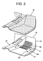
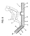
- FIG 1 there is shown a portion under the feet of a front-seat occupant M on a floor of an automobile having a front and a back seat. Under the feet of the occupant of the automobile, there is provided a body panel 20 and, on the side held apart from the body panel 20 toward the cabin, there is laid down a floor carpet (floor covering) 30.
- the body panel 20 has a flat portion 22 extended, substantially horizontally, rearward from the bottom of the feet of the front-seat occupant M and a rising wall portion 24 rising obliquely frontward and, from the front edge of the flat portion 22 so as to define its boundary with an engine room.
- the flat portion 22 is also called a floor panel and the rising wall portion 24 is also called a dash-panel.
- a center console 28 dividing the driver's seat and the assistant driver's seat, and others, as shown in FIG 2.
- the floor carpet 30 is disposed along the shape of the body panel 20, as extended substantially horizontally in a rearward direction from the bottom of the front-seat occupant M and extended forward and raised obliquely upward from the bottom of the feet of the front-seat occupant M.
- a tibia pad 10 as an impact absorbing body of the present invention is interposed between the body panel 20 and the floor carpet 30 as laid on the flat portion 22 of the body panel and on the rising wall portion 24.
- the floor carpet 30 formed into a required shape is laid on the tibia pad 10.
- the floor carpet 30 which is molded into a form fit along the profile of the flat portion 22 of the body panel and the rising wall portion 24 so as to cover all over the floor of the occupant cabin, is laid on the body panel 20.
- a tuft carpet produced by having raised pile stitched into a ground fabric, a needle punch carpet produced by needling nonwoven webs so as to interlink the fibers together, and the like is used.
- the backside 30a of the floor carpet 30 is lined with a thin sheet of a thermoplastic resin material with a low melting point, such as low density polyethylene and ethylene vinyl acetate. By press forming the lining material, under heated and plasticized condition, into a required shape, the shape to fit onto the body panel 20 of the automobile can be provided.
- a strong impact exerting a push in an obliquely upward and backward, is given to the boundary 26 between the flat portion 22 and the rising wall portion 24 of the body panel, where the feet of the front-seat occupant M are placed.
- a strong impulsive load comes to be imposed on the feet of the occupant M. Therefore, a material for absorbing the impact, called a tibia pad, is disposed at the boundary 26 as interposed between the body panel 20 and the floor carpet 30.
- the tibia pad 10 is disposed, in the automobile occupant cabin, at least at one of the portions under feet of the drivers' seat and under the feet of the assistant driver's seat.
- a single impact absorbing body may be disposed as extended from the portion under the feet of the driver's seat to the portion under the feet of the assistant driver's seat.
- a raising material 40 As the raising material 40, a porous and highly sound absorbing material is preferable and, therefore, a fabric felt of various types is most suitable.
- a synthetic fiber felt manufactured first, by piling up polyester fibers with a fiber diameter of 1 - 5 d and a fiber length of 20 - 70 mm and, then, by partially allowing the fibers to be fused-bonded together to provide a density of 0.04 - 0.1 g/cm 3 , can be mentioned.
- the tibia pad 10 is provided by integrally forming its horizontal portion 10a, which is horizontally laid on the portion under the feet of the occupant, and an oblique portion 10b, which is slanted a predetermined angle with respect to the horizontal portion 10a and disposed along the rising wall portion 24 obliquely raised, in front of the horizontal portion, toward its boundary with the engine room.
- the tibia pad 10 may be fixed to the body panel 20 by clips or may be glued onto the backside of the floor carpet 30.
- the raising material 40 may also be fixed to the body panel 20 by clips or glued onto the backside of the floor carpet 30.
- a foamed material is preferred in view of sound absorption.
- a material produced by foaming a synthetic resin material is much preferred. While an impact is transmitted from the tibia pad 10 to the feet of the occupant through the floor carpet 30 at the time of a collision, the impact to the feet of the occupant can then be lowered because the foamed synthetic resin material having a relatively low rigidity absorbs the impact.
- a thermoplastic resin is preferred in view of its easiness of being molded and such as polypropylene, polystyrene, and polyethylene can be used. Polypropylene is especially preferred in view of its difficulty of being broken, shape restoration, and heat resistance.
- a foam plastic material obtained by foaming a plastic material by mixing a foaming agent therein may be extruded from a predetermined mold so as to be molded, or a beaded plastic material may be impregnated with a foaming agent to be preliminarily foamed and, then, the material may be filled into a metallic mold and heated so as to be foamed further and molded.
- foaming agents volatile foaming agents generating hydrocarbons such as butane and pentane, inorganic foaming agents such as ammonia carbonate generating carbon dioxide etc., and the like may be used.
- a case where a foamed-bead molding is used will be described, where the molding is produced by preparing pre-foamed resin granules by impregnating a synthetic resin material with a foaming agent and molding an aggregate of the resin granules by allowing them to be fused together.
- a foaming agent such as B-BLOCK_(EPP) and STYLO-DIA (EPS), both being trade names of products manufactured by Kabushiki Kaisha JSP, can be used.
- the density of the molding, controlled by the foaming factor is within the range of around 0.02 - 0.09 g/cm 3 and, in terms of its mechanical property, that having a 50%-compression-strength of around 0.1 - 0.5 MPa is preferred.
- the thickness, width, and depth (along the surface) are set to be around 30mm, around 400mm, and around 300mm, respectively.
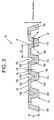
- FIG 3 shows a vertical section of the tibia pad at the position of the line A1 - A1 in FIG 2.
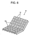
- the tibia pad 10 is formed such that a plurality of V-lettered supporting legs 12 (load supporting portions) each thereof having a V-lettered section, forming grooves 10c running in parallel with the face 20a facing toward the cabin of the body panel 20, are arranged side by side along the face 20a facing toward the cabin of the body panel 20, and each of the neighboring V-lettered supporting legs 12 are connected to be fixed by a bridge portion 14 in a flat plate shape.
- each V-lettered supporting leg 12 When a pair of the supporting legs of each V-lettered supporting leg 12 are denoted as a left-hand supporting leg 12a and a right-hand supporting leg 12b, it can be said that the neighboring V-lettered supporting legs 12 are fixed by connecting the right-hand supporting leg 12b of the V-lettered supporting leg to the left of the drawing, and the left-hand supporting leg 12a of the V-lettered supporting leg to the right of the drawing, by the bridge portion 14.
- the tibia pad 10 of the present embodiment is arranged such that the V-lettered supporting leg disposed at the left-hand edge has only its right-hand supporting leg 12b, while the V-lettered supporting leg disposed at the right-hand edge has only its left-hand supporting leg 12a.
- both the left-hand and right-hand edges of the tibia pad may be provided by V-lettered supporting legs formed of the supporting legs 12a, b, or, otherwise, by the bridge portions 14.
- each of the neighboring V-lettered supporting legs 12 have their ends 12d, e on the side toward the floor carpet connected by flat-plate-shaped bridge portion 14. More specifically, the tibia pad 10 is such a shape that is formed by bending a sheet of plate. Since, the end portions on the side toward the carper are connected by the bridge portion in fixing the neighboring load supporting portions together, the shape of the impact absorbing body is further stabilized and therefore it can stably provide a better impact absorbing performance over a long time.
- each of the V-lettered supporting legs 12 and the bridge portions 14 are formed into a shape stretched from the flat portion 22 of the body panel to the rising wall portion 24 and arranged to have a continuous long size forwardly extended from the portion under the feet of the occupant to the front portion. Accordingly, in the molding process of the tibia pad, it can be easily removed from the mold, and in addition, the tibia pad, integrally formed of the oblique portion 10b and the flat portion 10a such that the former is obliquely extended from the latter, has no possibility of being broken when it is transported before being build onto an automobile.
- each V-lettered supporting leg 12 is preferred to be within the range of 6 - 15 mm, while the wall thickness d 3 of the bridge portion 14 is preferred to be within the range of 3 - 15 mm.
- the thickness d 1 not smaller than 6 mm and the thickness d 3 not smaller than 3 mm prevents the tibia pad 10 from easily buckling so that the impact absorbing performance can be stabilized.
- the thickness d 1 not larger than 6 mm and the thickness d 3 not larger than 15 mm allows the tibia pad, when subjected to an impact, to sufficiently deform so that the impact absorbing performance can be bettered.
- the length d 2 of the face facing toward the cabin of the bridge portion 14 in the direction parallel to the face 20a facing toward the cabin of the body panel 20 and in the direction perpendicular to the groove 10c formed in the V-lettered supporting legs 12 is preferred to be within the range of 20 - 50 mm. This length will be called "span.”
- span d 2 When the span d 2 is made larger than 20 mm, the degree of freedom of deformation of the V-lettered supporting legs becomes sufficiently high and a better impact absorbing performance can be provided.
- the span d 2 is made smaller than 50 mm, the tibia pad hardly causes buckling and a stabilized impact absorbing performance can be provided.
- the wedge angle ⁇ on the cross-section of the groove 10c formed between the V-lettered supporting legs 12 is preferably set to be within the range of 5 - 60° and much preferably set to be within the range of 20 - 40°. If the wedge angle ⁇ is set to be 5° or above, or much preferably, set to be 20° or above, the degree of freedom of deformation of the V-lettered supporting legs becomes higher and a better impact absorbing performance can be provided. Whereas, if the wedge angle 8 is set to be 60° or below, or much preferably set to be 40° or below, the tibia pad is prevented from easily buckling and therefore a stabilized impact absorbing performance can be provided.
- the above mentioned dimensions of the tibia pad are such that were determined through measurements of responsive loads occurring when impactive deformations were actually given to tibia pads.
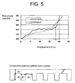
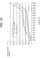
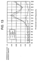
- a simulation model of the lower leg bottom portion having a sectional area of 90 cm 2 was subjected to a collision in its thickness direction at a speed not less than 3.0 m/sec and the responsive loads impressed on the simulation model of the lower leg bottom portion through the tibia pad were measured and recorded on a graph with the deformation (displacement) length L1 (unit: mm) taken along the axis of abscissas and the responsive load L2 (unit: kN) taken along the axis of ordinate.
- the solid line in the graph of FIG. 5 indicates the results of record of responsive loads against displacements of one of the tibia pads to which the present invention was applied and the dotted line in the graph indicates the results of record of responsive loads against displacements of a tibia pad as a comparative example, having its vertical cross-section indicated at the bottom of the graph.
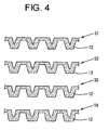
- the tibia pad of the comparative example is configured such that a plurality of load supporting portions, each having a rectangular section, are arranged side by side along the face facing toward the cabin of the body panel, while upper edge portions of the load supporting portions are each fixed to a flat plate portion in a flat-plate shape.
- the thickness d 11 of each load supporting portion is set to be 12mm, the distance d 12 between adjoining load supporting portions to 18 mm, the thickness d 13 of the flat plate portion to 12 mm, and the height d 14 of each load supporting portion to 18 mm.
- the responsive load rises relatively greatly according as the displacement increases while the displacement is relatively small (around 0 - 7 mm in the graph), and thereafter, the range where the responsive load is kept below 3.0 kN and it becomes flat (the range within which the displacement is from 7 to 18 mm or so in the graph) is lasting long, and thus, the impact energy generated at the time of collision is suitably absorbed.
- the displacement in the graph where the absorbed energy has reached 30J is indicated by the circle O.
- the responsive load is gradually rising according as the displacement is increased, the trajectory is rising monotonously from left to right with the responsive load increased, and the point where the responsive load exceeds a value of 3.0 kN is reached relatively earlier, and therefore, the impact absorbing performance of it is lower than that of the tibia pad to which the present invention is applied.
- the displacement becomes greater until the absorbed energy by the tibia pad reaches 30J, which energy is obtained by integrating the responsive load L2, dependent on the displacement L1, with respect to the displacement L1, and therefore, the comparative example is unable to absorb impact energy greater than 30J at the point where the responsive load exceeds 3.0 kN. Also from this point, its impact absorbing performance is lower than that of the tibia pad to which the present invention is applied.
- the displacement at the point where the absorbed energy has reached 30J is indicated by x.
- the tibia pad 10 is configured such that the responsive load occurring when the tibia pad is compressed in its thickness direction (the vertical direction in FIG 3) has reached 30J becomes smaller than 3.0 kN.
- Such a tibia pad can be provided by adjusting the above mentioned parameters d 1 - d 3 and ⁇ .
- each V-lettered supporting leg 12 when it becomes too large, the responsive load at the point where the absorbed energy reaches 30J exceeds 3.0 kN, whereas when it becomes too small, the V-lettered supporting leg becomes easily broken and the responsive load at the point where the absorbed energy reaches 30J exceeds 3.0 kN.
- the thickness d 3 of the bridge portion 14 when it becomes too large, the deformation of the V-lettered supporting legs are controlled more strictly than necessary and, hence, the impact energy comes to be absorbed only by the compressive action and the responsive load where the absorbed energy reaches 30J exceeds 3.0 kN.
- the bridge portion comes to be easily broken, and, hence, the fixing capability of the supporting leg is lowered and the responsive load where the absorbed energy reaches 30J exceeds 3.0 kN.
- the V-lettered supporting legs With respect to the wedge angle ⁇ of the V-lettered supporting legs, if it becomes too large, the V-lettered supporting legs come to be buckled easily before being compressed or deformed and, hence, the responsive load at the point where the absorbed energy becomes 30J exceeds 3.0 kN, whereas, if it becomes too small, the degree of freedom in making deformation of the V-lettered supporting legs becomes too small and, hence, the responsive load at the point where the absorbed energy becomes 30J exceeds 3.0 kN.
- d 1 - d 3 and ⁇ allowing the responsive load at the point where the absorbed energy reaches 30J to be smaller than 3.0 kN are found to be, as described above, d 1 is 6 - 15 mm, d 3 is 3 - 15 mm, d 2 is 20 - 50 mm, and ⁇ is 5 - 60° (much preferably, 20 - 40°). Since, as seen from the above, the absorbed energy as large as 30J can be absorbed while the responsive load is lower than 3.0 kN, the present embodiment provides a good impact absorbing performance.
- the V-lettered supporting legs 12 With regard to the orientation in installing the V-lettered supporting legs 12, having it oriented in the front-back direction of the automobile as shown in FIG 2 is preferred to having it oriented in the left-right direction of the automobile. This is because of such mechanical reasons that, in the case of head-on collision of the automobile, an impact is produced in the front-back direction, and, therefore, the V-lettered supporting legs, if oriented in left-right direction of the automobile, receive at the time of occurrence of an impact such a force that flattens the V-lettered supporting legs in their cross-sectional direction; whereas, if the V-lettered supporting legs are oriented in front-back direction of the automobile, the V-lettered supporting legs hardly receive at the time of occurrence of an impact such a force that flattens the V-lettered supporting legs in their cross-sectional direction.
- the sounds such as the road noise and the engine noise entering the cabin are introduced onto the backside of the floor carpet and absorbed thereby by the action of resonance decay. Accordingly, the sound absorbing and sound insulating performance can be improved. According to the present invention, as described above, a good impact absorbing performance at the time of incoming of an impact can be provided in a stabilized manner.
- the above mentioned cylindrical resin granule can be produced by using known art.
- a thermoplastic resin as polypropylene may be fed into a kneading extrusion molding machine with a heater so that the resin is melted by heating with the heater, the molten resin may be extruded by the extruder from a mold having a ring shaped extrusion outlet into a cylindrical form, and the cylindrical resin may be cut to a predetermined length, and thus, cylindrical granules (pellets) being sufficiently small and having uniform diameter may first be prepared.
- a plurality of the thus obtained granules may be cast into an autoclave to impregnate the granule with a predetermined amount of a foaming agent in an atmosphere of a predetermined pressure and temperature. Then, by taking out the plurality of granules to an ambient atmosphere under a normal pressure, a plurality of foamed cylindrical resin granules may be provided.
- a plurality of cylindrical resin granules may also be provided by mixing a foaming agent into a thermoplastic resin material, extruding the foamed thermoplastic resin material from a mold provided with a ring-shaped extruding outlet into a cylindrical shape, and cutting the resin cylinder to a predetermined length.
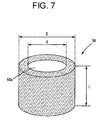
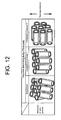
- the impact absorbing body formed of such cylindrical resin granules on the whole is formed into a porous body. Since sound waves of the sounds entering the cabin are then caused to make irregular reflection upon entering the through holes 56a of the cylindrical resin granules 56, the energy of the entering sounds is absorbed by the impact absorbing body so that the sound is absorbed.
- the cylindrical resin granule 56 is given a cylindrical form with an inner diameter d of2 - 4 mm, an outer diameter D (D>d) of 4 - 6 mm, and a length L of 3 - 6 mm.
- These parameters are the parameters that affect the impact absorbing performance and sound absorbing performance of the impact absorbing body; by setting the inner diameter d, outer diameter D, and the length L to be within the above mentioned values, the impact absorbing body can be provided with good impact absorbing capability and sound absorbing capability.
- PEPP trade name for porous EPP
- Kabushiki Kaisha JSP can be used as such a cylindrical resin granule.
- the cylindrical resin granule may, other than the cylindrical cross-section, have a flattened, substantially elliptic, cross-section.
- a plurality of cylindrical resin granules 56 are used for producing the impact absorbing body, first by filling the plurality of cylindrical resin granules 56 into a predetermined mold adjusted to the shape of the impact absorbing body and then by introduced a high-temperature vapor into the mold to heat the interior of the mold so that the cylindrical resin granules 56 may be melted and bonded together, the impact absorbing body can be manufactured.
- the impact absorbing body manufactured by using cylindrical resin granules has a density of 0.02 - 0.1 g/cm 3 .
- the density By setting the density to be 0.02 g/cm 3 or above, a sufficient reactive force can be provided and, hence, the absorbed energy sufficiently increases. Therefore, the impact absorbing body is prevented from collapsing and generating an excessive reactive force.
- the density is set to be 0.1 g/cm 3 or below, it is prevented that an excessive reactive force is generated at an earlier stage. Besides, the sound absorbing performance is bettered.
- an impact absorbing body When an impact absorbing body is manufactured by molding an aggregate of a plurality of cylindrical resin granules of foamed polypropylene into a molding having an inner diameter of 2 - 4 mm, an outer diameter of 4 - 6 mm, and a length of 3 - 6 mm, the density of the thus obtained impact absorbing body becomes 0.03 - 0.05 g/cm 3 .
- the above mentioned impact absorbing body can be manufacture through various methods.
- a plurality of foamed cylindrical resin granules 56 are filled into a mold, which is provided with a plurality of steam bents and formed into the shape of an impact absorbing body, and then the mold is clamped.
- the steam bent provided in the mold is made smaller than whichever of the outer diameter or the length of the cylindrical resin granule that is the smaller, so that the cylindrical resin granules filled into the mold may not come out through the vapor bents.
- vapors elevated in temperature by a specific heater to such a temperature as to allow the thermoplastic resin forming the cylindrical resin granules to be melted are introduced into the mold.
- the interior of the mold can be heated and the cylindrical resin granules 56 are melted to be bonded together and, thus, the impact absorbing body can be produced. If the mold is opened after the interior of the mold has been cooled down, the produced impact absorbing body can be taken out.
- an impact absorbing body molded from an aggregate of a plurality of cylindrical resin granules, which are prepared by foaming a plastic resin material and shaping the same into a cylindrical form can be manufactured.
- the cylindrical resin granule is provided with a through hole, by introducing high-temperature vapors into the mold, the entire space within the mold can be easily heated and the impact absorbing body can be easily produced.
- the sound absorbing performance can be improved and the level of stillness of the cabin can be improved.
- the impact absorbing body such that a plurality of the load supporting portions, each thereof having a V-lettered cross-section, forming grooves disposed parallel to the face facing toward the cabin of the body panel, are arranged side by side along the face facing toward the cabin of the body panel, and such that the neighboring load supporting portions are connected by a flat-plate-formed bridge portion, a good impact absorbing performance when subjected to an input impact can be stably obtained.
- the wall thickness d 1 of each V-lettered supporting legs 12 is 6 - 15 mm
- the thickness of the bridge portion 14 d 3 is 3 - 15 mm
- the length of the bridge portion on the side of the cabin d 2 is 20 - 50 mm
- the wedge angle on the cross-section of the groove formed by the V-lettered supporting legs ⁇ is 5 - 60° (much preferably, 20 - 40°).
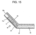
- an impact absorbing body 50 formed by using cylindrical resin granules 56 may be interposed between the rising wall portion 24 of the body panel 20 and the floor carpet 30.
- a fancy floor carpet 30 is laid, as an interior material, as spread over the flat portion 22 of the body panel and the rising wall portion 24 to decorate the cabin.
- the impact absorbing body 50 on the backside of the floor carpet 30, there are disposed the impact absorbing body 50, as located forwardly of the vicinity of the boundary between the flat portion 22 of the body panel 20 and the rising wall portion 24, and a raising material 40, which is porous and has a sound absorbing property, as located at the remaining portion.
- the floor carpet 30, the raising material 40, and the impact absorbing body 50 constitute an on-floor lying member 1.
- the lining of the floor carpet 30 serves the purpose of an adhesive agent when the impact absorbing body 50 and the raising material 40 are laminated on the backside 30a of the floor carpet 30.
- the raising material 40 can be made of the same material as that used in the first embodiment. If both the impact absorbing body 50 and the raising material 40 are adhesively attached to the lining of the floor carpet 30, it is favorable because the impact absorbing body 50 and the raising material 40 do not shift their positions. Further, if the gap between the impact absorbing body 50 and the raising material 40 is narrowed down or, much preferably, if the impact absorbing body 50 and the raising material 40 are arranged in touch with each other, it is favorable because penetration of a sound through the gap can then be prevented. Here, there is a tendency that much road noise No comes in through the flat portion 22 and much engine noise N 1 comes in through the rising wall portion 24.
- the present impact absorbing body 50 is provided by a molding of cylindrical resin granules, it, in corporation with the raising material 40 having a good sound absorbing performance, absorbs noise No, N 1 to thereby improve the stillness of the cabin. If, the individual cylindrical resin granules are provided with the features as mentioned below, the sound absorbing performance and sound insulating performance can further be improved.
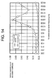
- a test sample of a comparative example (of which the air permeability was set to 41 cc/cm 2 /sec) was prepared by molding cylindrical resin granules of the same resin material and size as the embodiment and having the inner side of the cylinder smoothed, into a body with the same size as the embodiment (a thickness of 20 mm and a density of 0.04 g/cm 3 ). Thereafter, evaluation of both test samples was carried out by measuring difference therebetween in the vertical-incidence sound absorption coefficient.
- the vertical-incidence sound absorption coefficient of the test sample of the embodiment with the inner face of the cylinder roughened was better than that of the test sample of the comparative example in each of frequency ranges, and thus the effect of improvement in the sound absorbing performance by roughening the cylinder inner surface has been verified.
- test sample (of which the air permeability was set to 41 cc/cm 2 /sec) was prepared by using non-flattened cylindrical resin granules and molding such granules into the same shape as the test sample of the embodiment (with a thickness of 20 mm and density of 0.04 g/cm 3 ). Then, both of the test samples were evaluated by measuring the difference therebetween in the vertical-incidence sound absorption coefficient (averaged on the range of 1000 - 6300 Hz).
- an impact absorbing body is produced by molding an aggregate of cylindrical resin granules into a shape having convexities and concavities on its face facing toward outside the automobile and piling a sheet of felt on the surface having the convexities and concavities thereon, then the sound absorbing performance is improved and occurrence of squeaking sound between the impact absorbing body and the body panel can also be suppressed more certainly.
- This can also be said of the first embodiment not using cylindrical resin granules.
- the impact absorbing body 72 shown in FIG 16 includes the molding 73 which has an aggregate of cylindrical resin granules molded into a shape having convexities and concavities on the face 73a facing toward outside the automobile and a sheet of felt 74 laminated on the face 73a thereof facing toward outside the automobile such that the convexities and concavities formed on the molding are filled up thereby.
- the surface area between the molding and the felt is increased due to formation of the convexities and concavities on the face facing toward outside the automobile of the molding made of cylindrical resin granules. This leads to an increase in the entering area of sound waves and, hence, the sound absorbing performance is improved.
- the air permeability of the felt is much greater than the air permeability of the molding made from cylindrical resin granules, the sound absorbing performance can be improved by the increase of the surface area of the molding.
- the convexity of the convex and concave shape is formed into a trapezoidal shape.
- the sound absorbing performance of the sound absorbing molding 73 of molded cylindrical resin granules is combined with the sound absorbing performance of the felt 74, a higher sound absorbing performance is achieved. Further, the squeaking sound due to rubbing between the impact absorbing body 72 and the body panel can be eliminated more certainly.
- the molding 73 and the felt 74 can be adhesively bonded together by an adhesive or hot-melt adhesive. Further, by inserting the felt into the molding die before the molding 73 is molded, the molding 73 and the felt 74 can be molded integral by the molding.
- a tufted carpet (weight per unit area: 650 g/m 2 ) produced by tufting pile of PET fibers into a ground fabric was used and a polyethylene resin sheet is provided as the backing on the backside (200g/ m 2 ).
- a carpet formed into a shape to be substantially fitted over the body panel of the test vehicle was used.
- the air permeability of the floor carpet was 0 cc/c m 2 /sec.
- On the backside of the floor carpet there was disposed an impact absorbing body with a thickness of 30 mm as stretched from the flat portion of the body panel to the rising wall portion, such that the projected area thereof would become 0.15 m 2 .
- an impact absorbing body capable of stably attaining good impact absorbing performance at inputting of an impact. Further, according to an impact absorbing body obtained by molding cylindrical resin granules, the sound absorbing performance and sound insulating performance can be improved while a good impact absorbing performance is maintained and, thus, cabin stillness can further be improved.
Landscapes
- Engineering & Computer Science (AREA)
- Mechanical Engineering (AREA)
- Vehicle Interior And Exterior Ornaments, Soundproofing, And Insulation (AREA)
- Passenger Equipment (AREA)
- Body Structure For Vehicles (AREA)
Applications Claiming Priority (3)
| Application Number | Priority Date | Filing Date | Title |
|---|---|---|---|
| JP2003388684A JP4437662B2 (ja) | 2003-11-19 | 2003-11-19 | 自動車用フロア敷設体 |
| JP2004141980A JP4416567B2 (ja) | 2004-05-12 | 2004-05-12 | ティビアパッド |
| PCT/JP2004/016950 WO2005049386A1 (fr) | 2003-11-19 | 2004-11-15 | Corps amortissant les chocs |
Publications (2)
| Publication Number | Publication Date |
|---|---|
| EP1693255A1 true EP1693255A1 (fr) | 2006-08-23 |
| EP1693255A4 EP1693255A4 (fr) | 2007-11-21 |
Family
ID=34622173
Family Applications (1)
| Application Number | Title | Priority Date | Filing Date |
|---|---|---|---|
| EP04818884A Withdrawn EP1693255A4 (fr) | 2003-11-19 | 2004-11-15 | Corps amortissant les chocs |
Country Status (3)
| Country | Link |
|---|---|
| US (1) | US20070080562A1 (fr) |
| EP (1) | EP1693255A4 (fr) |
| WO (1) | WO2005049386A1 (fr) |
Cited By (3)
| Publication number | Priority date | Publication date | Assignee | Title |
|---|---|---|---|---|
| DE102008047699A1 (de) * | 2008-09-18 | 2010-03-25 | GM Global Technology Operations, Inc., Detroit | Mit Energieabsorbern ausgestatteter Fahrgastraum eines Kraftfahrzeugs |
| EP2500194A3 (fr) * | 2011-03-15 | 2015-06-10 | Kyoraku Co., Ltd. | Absorbeur d'énergie de choc pour véhicule et procédé de formation de celui-ci |
| CN107542824A (zh) * | 2017-10-13 | 2018-01-05 | 中国石油大学(华东) | 一种模仿环节动物的仿生减震结构 |
Families Citing this family (8)
| Publication number | Priority date | Publication date | Assignee | Title |
|---|---|---|---|---|
| US7775584B2 (en) * | 2008-04-14 | 2010-08-17 | Honda Motor Co., Ltd. | Impact absorbing armrest for a motor vehicle |
| US8857895B2 (en) * | 2011-06-17 | 2014-10-14 | David J. Millar | Tibia force reduction wedge |
| US9022451B2 (en) | 2011-06-23 | 2015-05-05 | Toyota Jidosha Kabushiki Kaisha | Tibia pad and tibia pad installation structure |
| WO2013094691A1 (fr) * | 2011-12-20 | 2013-06-27 | 新日鐵住金株式会社 | Panneau de plancher avant |
| JP6598055B2 (ja) * | 2015-07-30 | 2019-10-30 | いすゞ自動車株式会社 | インシュレータの取付構造 |
| US10315603B2 (en) | 2017-09-28 | 2019-06-11 | Nissan North America, Inc. | Vehicle footrest impact deflection member |
| FR3084305B1 (fr) * | 2018-07-25 | 2021-01-15 | Faurecia Interieur Ind | Structure de support pour vehicule et vehicule associe |
| JP7414793B2 (ja) * | 2021-12-17 | 2024-01-16 | 本田技研工業株式会社 | 車両用フロアカーペット |
Family Cites Families (35)
| Publication number | Priority date | Publication date | Assignee | Title |
|---|---|---|---|---|
| US1736572A (en) * | 1926-09-29 | 1929-11-19 | Charles C Berg | Floor mat for automobiles |
| US2057873A (en) * | 1933-02-02 | 1936-10-20 | Durkee Atwood Company | Floor covering |
| US2052605A (en) * | 1935-03-25 | 1936-09-01 | Samuel C Clark | Flexible backing for floor coverings and the like |
| US2192516A (en) * | 1937-05-28 | 1940-03-05 | Woodall Industries Inc | Insulation sheet material |
| US2709105A (en) * | 1952-08-23 | 1955-05-24 | Ford Motor Co | Motor vehicle floor mat |
| US2810672A (en) * | 1956-06-08 | 1957-10-22 | Don A Taylor | Floor mats for automobiles |
| US3390912A (en) * | 1966-05-06 | 1968-07-02 | Stanley S. Stata | Floor mat and locating frame combination for motor vehicles |
| US3387315A (en) * | 1966-09-15 | 1968-06-11 | Stanley S. Stata | Shoe scraper floor gratings for automobile floors |
| JPS5445609Y2 (fr) * | 1972-03-13 | 1979-12-27 | ||
| DE2921050A1 (de) * | 1979-05-23 | 1980-11-27 | Fraunhofer Ges Forschung | Schallabsorbierendes bauelement aus kunststoff-folie |
| JPS61235278A (ja) * | 1984-11-26 | 1986-10-20 | Ikeda Bussan Co Ltd | 車両等のフロア構造 |
| CA1322876C (fr) * | 1986-01-22 | 1993-10-12 | Tadao Inabata | Materiau metallique composite leger, et methode de production connexe |
| JPS62184947A (ja) * | 1986-02-10 | 1987-08-13 | Eiji Adachi | 積層内装材 |
| US5023139A (en) * | 1989-04-04 | 1991-06-11 | Research Corporation Technologies, Inc. | Nonlinear optical materials |
| JPH06183293A (ja) | 1991-01-17 | 1994-07-05 | Hayashi Gijutsu Kenkyusho:Kk | 自動車用フロアカーペット |
| JPH0512268U (ja) * | 1991-07-31 | 1993-02-19 | 日産車体株式会社 | 車室内の前部床面構造 |
| CN1112582A (zh) * | 1993-09-21 | 1995-11-29 | 积水化学工业株式会社 | 由聚烯烃基料树脂和硅烷改性的聚合物组成的泡沫塑料及其制备方法 |
| US5665943A (en) * | 1995-06-15 | 1997-09-09 | Rpg Diffusor Systems, Inc. | Nestable sound absorbing foam with reduced area of attachment |
| JPH0924757A (ja) * | 1995-07-10 | 1997-01-28 | Hayashi Gijutsu Kenkyusho:Kk | 自動車用フロアカーペット緩衝材 |
| CN100363430C (zh) * | 1996-05-10 | 2008-01-23 | 西西阿-株式会社 | 组合物 |
| US6818161B2 (en) * | 1997-04-01 | 2004-11-16 | Jsp Corporation | Molded body of thermoplastic resin having sound absorption characteristics |
| JP3980707B2 (ja) | 1997-05-28 | 2007-09-26 | 本田技研工業株式会社 | 自動車の車体構造 |
| US6199942B1 (en) * | 1998-02-04 | 2001-03-13 | Oakwood Energy Management, Inc. | Modular energy absorbing assembly |
| JPH11348699A (ja) * | 1998-06-12 | 1999-12-21 | Toyota Motor Corp | 車両用内装部品の衝撃吸収構造 |
| US6224133B1 (en) * | 1998-11-04 | 2001-05-01 | Ford Global Technologies, Inc. | Secondary floor assembly |
| JP2001026246A (ja) * | 1999-07-12 | 2001-01-30 | Sekisui Plastics Co Ltd | 自動車用内装材 |
| JP2001080439A (ja) * | 1999-09-17 | 2001-03-27 | Mitsubishi Motors Corp | エネルギ吸収部材 |
| JP3695267B2 (ja) * | 1999-12-08 | 2005-09-14 | 日産自動車株式会社 | 車両用フットレスト |
| US7377084B2 (en) * | 2000-04-24 | 2008-05-27 | Hunter Douglas Inc. | Compressible structural panel |
| WO2002059870A1 (fr) * | 2001-01-23 | 2002-08-01 | Kasai Kogyo Co., Ltd. | Materiau insonorise pour vehicule et son procede de fabrication |
| JP2002331895A (ja) | 2001-05-10 | 2002-11-19 | Toyota Motor Corp | 自動車の車体構造 |
| JP2003127796A (ja) | 2001-10-26 | 2003-05-08 | Hitachi Chem Co Ltd | 衝撃吸収性自動車用フロアスペーサ |
| JP4207592B2 (ja) * | 2003-02-13 | 2009-01-14 | 三菱自動車工業株式会社 | 車両のフロア構造 |
| US7901770B2 (en) * | 2003-11-04 | 2011-03-08 | Boston Scientific Scimed, Inc. | Embolic compositions |
| JP4531468B2 (ja) * | 2004-07-14 | 2010-08-25 | 小島プレス工業株式会社 | 車両用衝撃吸収構造体及びその取付構造 |
-
2004
- 2004-11-15 WO PCT/JP2004/016950 patent/WO2005049386A1/fr not_active Ceased
- 2004-11-15 US US10/579,398 patent/US20070080562A1/en not_active Abandoned
- 2004-11-15 EP EP04818884A patent/EP1693255A4/fr not_active Withdrawn
Non-Patent Citations (2)
| Title |
|---|
| No further relevant documents disclosed * |
| See also references of WO2005049386A1 * |
Cited By (5)
| Publication number | Priority date | Publication date | Assignee | Title |
|---|---|---|---|---|
| DE102008047699A1 (de) * | 2008-09-18 | 2010-03-25 | GM Global Technology Operations, Inc., Detroit | Mit Energieabsorbern ausgestatteter Fahrgastraum eines Kraftfahrzeugs |
| EP2500194A3 (fr) * | 2011-03-15 | 2015-06-10 | Kyoraku Co., Ltd. | Absorbeur d'énergie de choc pour véhicule et procédé de formation de celui-ci |
| US9079476B2 (en) | 2011-03-15 | 2015-07-14 | Kyoraku Co., Ltd. | Impact energy absorber for vehicle and method for forming the same |
| US9463761B2 (en) | 2011-03-15 | 2016-10-11 | Kyoraku Co., Ltd. | Impact energy absorber for vehicle and method for forming the same |
| CN107542824A (zh) * | 2017-10-13 | 2018-01-05 | 中国石油大学(华东) | 一种模仿环节动物的仿生减震结构 |
Also Published As
| Publication number | Publication date |
|---|---|
| WO2005049386A1 (fr) | 2005-06-02 |
| US20070080562A1 (en) | 2007-04-12 |
| EP1693255A4 (fr) | 2007-11-21 |
Similar Documents
| Publication | Publication Date | Title |
|---|---|---|
| EP1693255A1 (fr) | Corps amortissant les chocs | |
| US5884962A (en) | Impact absorption member | |
| JPS6163784A (ja) | 成形フオ−ム裏打ちじゆたん集成体及びその製造方法 | |
| EP1078821B1 (fr) | Garniture de pavillon pour véhicule et produits analogues | |
| JP5936848B2 (ja) | 車両用シート及びその製造方法 | |
| US20060105661A1 (en) | Thermoplastic formed panel, intermediate panel for the fabrication thereof, and method for fabricating said panel and said intermediate panel | |
| JPS6220746A (ja) | 消音用発泡体裏材を有する成形敷物 | |
| JP2001508005A (ja) | デカップラを備えた音響バリア | |
| JP7182541B2 (ja) | 吸音性防音部材の製造方法、及び吸音性防音自動車内装部材 | |
| CN109952608A (zh) | 声学泡沫去耦器 | |
| AU2002343969B2 (en) | Floor laying material, piece mat, and arranging structure thereof | |
| US20240066764A1 (en) | Method for manufacturing a seat padding, seat padding as such, and seat as such | |
| WO2007123232A1 (fr) | Cale de sol pour véhicule et structure intérieure de véhicule | |
| JP4359177B2 (ja) | 防音性を付与した車両用下肢部衝撃吸収パッド | |
| JPH0716867A (ja) | 自動車用内装部材の緩衝構造 | |
| JP4437662B2 (ja) | 自動車用フロア敷設体 | |
| JP4963818B2 (ja) | 車両用下肢部衝撃吸収パッド | |
| JP4996335B2 (ja) | 車両用フロアカーペット | |
| JP4533709B2 (ja) | 衝撃吸収構造体および衝撃吸収構造体の製造方法 | |
| RU2342895C2 (ru) | Способ изготовления амортизирующего материала из формованного полимерного продукта (варианты) и амортизирующий материал (варианты) | |
| JP4147146B2 (ja) | 吸音フロア | |
| JP4416567B2 (ja) | ティビアパッド | |
| JP7414793B2 (ja) | 車両用フロアカーペット | |
| JP2007001373A (ja) | 衝撃吸収体 | |
| JP2010120471A (ja) | 衝撃吸収構造体 |
Legal Events
| Date | Code | Title | Description |
|---|---|---|---|
| PUAI | Public reference made under article 153(3) epc to a published international application that has entered the european phase |
Free format text: ORIGINAL CODE: 0009012 |
|
| 17P | Request for examination filed |
Effective date: 20060522 |
|
| AK | Designated contracting states |
Kind code of ref document: A1 Designated state(s): AT BE BG CH CY CZ DE DK EE ES FI FR GB GR HU IE IS IT LI LU MC NL PL PT RO SE SI SK TR |
|
| DAX | Request for extension of the european patent (deleted) | ||
| A4 | Supplementary search report drawn up and despatched |
Effective date: 20071023 |
|
| 17Q | First examination report despatched |
Effective date: 20080526 |
|
| STAA | Information on the status of an ep patent application or granted ep patent |
Free format text: STATUS: THE APPLICATION IS DEEMED TO BE WITHDRAWN |
|
| 18D | Application deemed to be withdrawn |
Effective date: 20081007 |