EP1696155A2 - Bürstendichtunganordnung - Google Patents
Bürstendichtunganordnung Download PDFInfo
- Publication number
- EP1696155A2 EP1696155A2 EP06110093A EP06110093A EP1696155A2 EP 1696155 A2 EP1696155 A2 EP 1696155A2 EP 06110093 A EP06110093 A EP 06110093A EP 06110093 A EP06110093 A EP 06110093A EP 1696155 A2 EP1696155 A2 EP 1696155A2
- Authority
- EP
- European Patent Office
- Prior art keywords
- liquid
- brush
- rotation shaft
- cavity
- sealing
- Prior art date
- Legal status (The legal status is an assumption and is not a legal conclusion. Google has not performed a legal analysis and makes no representation as to the accuracy of the status listed.)
- Withdrawn
Links
- 239000007788 liquid Substances 0.000 claims abstract description 218
- 238000007789 sealing Methods 0.000 claims abstract description 45
- 238000012856 packing Methods 0.000 claims description 50
- 239000011347 resin Substances 0.000 claims description 31
- 229920005989 resin Polymers 0.000 claims description 31
- 125000006850 spacer group Chemical group 0.000 claims description 19
- 239000007789 gas Substances 0.000 claims description 7
- 239000011148 porous material Substances 0.000 claims description 6
- 238000005461 lubrication Methods 0.000 claims description 3
- 239000003507 refrigerant Substances 0.000 claims 1
- 238000003491 array Methods 0.000 description 6
- 238000007796 conventional method Methods 0.000 description 6
- 230000005484 gravity Effects 0.000 description 5
- 230000000694 effects Effects 0.000 description 4
- 239000000203 mixture Substances 0.000 description 4
- 238000004891 communication Methods 0.000 description 3
- 238000010276 construction Methods 0.000 description 3
- 239000000945 filler Substances 0.000 description 3
- 239000000463 material Substances 0.000 description 3
- 239000004809 Teflon Substances 0.000 description 2
- 229920006362 Teflon® Polymers 0.000 description 2
- 238000001816 cooling Methods 0.000 description 2
- 239000012530 fluid Substances 0.000 description 2
- 238000000034 method Methods 0.000 description 2
- UFHFLCQGNIYNRP-UHFFFAOYSA-N Hydrogen Chemical compound [H][H] UFHFLCQGNIYNRP-UHFFFAOYSA-N 0.000 description 1
- 238000005299 abrasion Methods 0.000 description 1
- 230000000712 assembly Effects 0.000 description 1
- 238000000429 assembly Methods 0.000 description 1
- 238000011109 contamination Methods 0.000 description 1
- 239000006185 dispersion Substances 0.000 description 1
- 239000000314 lubricant Substances 0.000 description 1
- 239000012466 permeate Substances 0.000 description 1
- 238000009423 ventilation Methods 0.000 description 1
Images


Classifications
-
- F—MECHANICAL ENGINEERING; LIGHTING; HEATING; WEAPONS; BLASTING
- F16—ENGINEERING ELEMENTS AND UNITS; GENERAL MEASURES FOR PRODUCING AND MAINTAINING EFFECTIVE FUNCTIONING OF MACHINES OR INSTALLATIONS; THERMAL INSULATION IN GENERAL
- F16J—PISTONS; CYLINDERS; SEALINGS
- F16J15/00—Sealings
- F16J15/002—Sealings comprising at least two sealings in succession
- F16J15/004—Sealings comprising at least two sealings in succession forming of recuperation chamber for the leaking fluid
-
- F—MECHANICAL ENGINEERING; LIGHTING; HEATING; WEAPONS; BLASTING
- F16—ENGINEERING ELEMENTS AND UNITS; GENERAL MEASURES FOR PRODUCING AND MAINTAINING EFFECTIVE FUNCTIONING OF MACHINES OR INSTALLATIONS; THERMAL INSULATION IN GENERAL
- F16J—PISTONS; CYLINDERS; SEALINGS
- F16J15/00—Sealings
- F16J15/16—Sealings between relatively-moving surfaces
- F16J15/32—Sealings between relatively-moving surfaces with elastic sealings, e.g. O-rings
- F16J15/3284—Sealings between relatively-moving surfaces with elastic sealings, e.g. O-rings characterised by their structure; Selection of materials
- F16J15/3288—Filamentary structures, e.g. brush seals
Definitions
- the invention relates to a liquid-sealing shaft seal apparatus for a rotary electrical machine using liquid, such as lubrication oil or seal oil, and to a rotary electrical machine using the shaft seal apparatus.
- large rotary electrical machines employ slider bearings using oil as a lubricant.
- hydrogen-cooled rotary electrical machines employ oil seals using sealing oil to seal hydrogen gas for cooling the interior of the machine inside of the rotary electrical machine.
- labyrinth seals are used to prevent lubrication oil, seal oil, or the like from leaking to the interior or exterior of a rotary electrical machine.
- the fluid may leak responsively following, for example, liquid state variations.
- a conventional liquid-sealing shaft seal apparatus of a rotary electrical machine which uses a brush seal, has a structure shown in FIG. 6.
- numeral 1 denotes a rotation shaft
- numeral 2 denotes a frame forming the exterior of the rotary electrical machine.
- the rotation shaft 1 is rotatably journaled by bearings (not shown) mounted on the frame 2.
- Numeral 3 denotes a brush holder.
- the brush holder 3 is robustly and hermetically fixed to the frame 2, and is mounted in such a manner as to close a space of the liquid atmosphere S1 (or, “liquid atmosphere space”, hereafter) and a space of the non-liquid atmosphere S2 (or, “non-liquid atmosphere space”, hereafter) in the rotary electrical machine.
- Numeral 4 denotes a brush seal formed in the manner that a brush 5 is clamped by a brush clamp 6.
- the brush seal 4 is configured such that multiple seal segments circumferentially split are combined into an annular state array, and that two arrays are arranged by circumferentially shifting split planes of the segments.
- Numeral 7 denotes packing formed similarly as the brush seal 4 such that multiple packing segments circumferentially split are combined in an annular state.
- the packing 7 thus formed is so mounted on an axial sidewall of the brush seal 4 that the sprit planes of the packing segments are circumferentially shifted with respect to those of the brush seal segments.
- Numeral 9 denotes a holding plate fixed with a bolt (not shown) on an axial sidewall of the brush holder 3 in order to fix the brush seal 4 and the packing 7 on the brush holder 3.
- a single-stage brush seal apparatus has been shown and described, an example having multiple brush seal assemblies arranged in multiple stages is disclosed in Jpn. Pat. Appln. KOKAI Publication No. 2001-295609.
- a rotary electrical machine of the type that has different liquids and that uses a shaft seal apparatus to avoid mixture of the liquids.
- a liquid different from a liquid contained in the atmosphere space S1 can be contained in the atmosphere space S2.
- the liquid leaks little by little from one of the atmosphere spaces S1 and S2 to the other, and a case takes place in which the different liquids are mixed with one another during operation over a long time, thereby hindering the operation of the rotary electrical machine.
- Another object of the invention is to provide a liquid-sealing shaft seal apparatus and a rotary electrical machine using the shaft seal apparatus, the shaft seal apparatus being capable of minimizing the amount of a mixture of different liquids in a rotary machine containing the different liquids.
- a liquid-sealing shaft seal apparatus comprising: a rotation shaft; a plurality of brush seals arranged in such a manner as to contact and surround the rotation shaft; and a brush holder which holds the brush seals, wherein the brush seals are arranged through a cavity in an axial direction of the rotation shaft, and the brush holder is provided with a liquid returning pass to return a liquid having leaked through the brush seals into the cavity to the side of an atmosphere in which a liquid is present as a sealing target.
- leakage liquids having leaked through the brush seals on the sides of the respective liquid atmospheres can be accumulated without causing dispersion thereof, and can be returned to the spaces on the sides of the liquid atmospheres through the respective liquid returning passes. Consequently, the amounts of liquids having leaked through the brush seals and accumulated in the spaces on the sides of the liquid atmospheres can be significantly reduced. Further, contamination by a different liquid can be significantly reduced.
- FIG. 1A is an axial cross-sectional view of a liquid-sealing shaft seal apparatus in a rotary electrical machine according to a first embodiment of the present invention.
- numeral 1 denotes a rotation shaft
- numeral 2 denotes a frame forming the exterior of a rotary electrical machine.
- the rotation shaft 1 is rotatably journaled by bearings (not shown) mounted to the frame 2.
- Numeral 3 is a brush holder.
- the brush holder 3 is robustly and hermetically fixed to the frame 2, and is mounted in such a manner as to close a liquid atmosphere space S1 and a non-liquid atmosphere space S2 in the rotary electrical machine.
- two brush seals spaced away from each other via a cavity 10 to be described later are stored. Namely, there are stored two-stage brush seals formed of a brush seal 4a on the side of the liquid atmosphere S1 and a brush seal 4b on the side of the non-liquid atmosphere S2.
- the brush seals 4a, 4b each are formed in the manner that a brush 5 is clamped by a brush clamp 6.
- the brush seal 4a, 4b each is formed such that multiple brush segments circumferentially split are combined into an annular state as an array, and that two arrays are arranged by shifting circumferentially split planes of the brush segments.
- the brush seal 4a has a structure formed of two brush seal discs 4a1 and 4a2 overlapped with each other.
- the one brush seal disc 4a1 is formed of tri-sectional brush seal pieces or segments 4a11, 4a12, and 4a13 circumferentially split.
- the other brush seal disc 4a2 is formed of tri-sectional brush seal pieces or segments 4a21, 4a22, and 4a23.
- a respective split plane of the brush seal disc 4a1, such as a split plane between the brush seal pieces 4a11 and 4a13, and a respective split plane of the other brush seal disc 4a2, such as a split plane between the brush seal pieces 4a21 and 4a22 are shifted by, for example, 60 degrees from each other in the circumferential direction.
- numeral 7 denotes a resin sheet packing formed of a resin sheet, such as Teflon (registered trademark). More specifically, the respective packing 7 is formed such that, similarly as the brush seal, multiple segments circumferentially split are combined in an annular state, and is mounted on each of axial sidewalls on both sides of the respective brush seals 4a, 4b such that an initial gap thereof with the rotation shaft 1 is zero. For example, as shown in FIG.
- a packing plate 7b of the packing 7 is so mounted on an axial sidewall of the brush seal 4a that the sprit planes of the packing segments 7b1, 7b2 and 7b3 are circumferentially shifted with respect to those of the segments 4a11, 4a12 and 4a13 of the brush seal 4a.
- the packing plate 7b has a bore 7bb contacting with the rotation shaft 1, and the packing plate 7a is formed in the similar manner as the plate 7b.
- Numeral 8 denotes a spacer inserted in an axial portion between the brush seals 4a and 4b axially provided in the two stages.
- Numeral 9 denotes a holding plate fixed with a bolt (not shown) on an axial sidewall of the brush holder 3 to fix the brush seals 4a and 4b, packing 7, and spacer 8, which are stored in the brush holder 3, into the brush holder 3.
- the liquid returning pass 12 is thus formed to return liquid QL, which has leaked into the cavity 10 from the liquid atmosphere space S1, to the liquid atmosphere space S1.
- Exterior portions of an axial-end bore portion 3a of the brush holder 3 and a bore portion 9a of the holding plate 9, respectively, are largely chamfered. This prevents liquid from accumulating in gaps between the respective exterior portions and the rotation shaft 1, but falls down under gravity.
- the initial gap with the rotation shaft 1 is set to zero, initial abrasion is caused when the rotation shaft 1 rotates.
- the gaps with the rotation shaft 1 and the resin sheet packing 7 are reduced to minimum gaps in size set in consideration factors including, for example, whirling resulting from eccentricity and the like of the rotation shaft 1, and the area of contact between the liquid and the brush 5 of the brush seal 4a is minimized. Therefore, since the liquid is permeated into the brush 5 of the brush seal 4a, the amount of the liquid QL leaking into the cavity 10 is significantly reduced.
- the cavity 10 exists, the leaked leakage liquid is not influence by the rotation of the rotation shaft 1, but falls in the gravitation direction and then flows into the liquid returning pass 12, whereby the liquid QL is returned into the liquid atmosphere space S1.
- the liquid atmosphere space S1 and the non-liquid atmosphere space S2 are in communication with each other through the through-hole 11, so that the pressure is the same in the spaces S1 and S2. Accordingly, no differential pressure is applied to the brush seal 4a, 4b, so that the amount of leakage liquid QL is not increased. Further, since the axial-end bore portion 3a of the brush holder 3 and the bore portion 9a of the holding plate 9 are largely chamfered to form an inclined plane, the liquid does not accumulates in the gaps between the respective chamfered portions and the rotation shaft 1. Consequently, the amount of liquid possibly in contact with the brush 5 of the brush seal 4a can be reduced.
- the present embodiment it is possible to reduce the amount of leakage liquid QL leaking through the brush seal 4a through the resin sheet packing 7, the axial-end bore portion 3a of the brush holder 3, the bore portion 9a of the holding plate 9, and the through-hole 11. Further, with the cavity 10 being arranged, the leakage liquid having leaked through the brush seal 4a on the side of the liquid atmosphere is prevented from dispersing in the cavity 10, but is guided to fall along the gravitation direction. Thereby, the liquid QL can be returned to the liquid atmosphere space S1 through the liquid returning pass 12. Consequently, the amount of liquid leaking into the non-liquid atmosphere space S2 through the brush seal 4b can be significantly reduced.
- FIG. 2 is an axial cross-sectional view of a liquid-sealing shaft seal apparatus in a rotary electrical machine according to a second embodiment of the present invention.
- Like reference characters are used in the drawing and description for portions identical to those in the first embodiment shown in FIG. 1.
- numeral 3 is a brush holder robustly and hermetically fixed to the frame 2, and is mounted in such a manner as to close a liquid atmosphere space Q and a liquid atmosphere space R in the rotary electrical machine.
- three brush seals spaced away from one another via cavities 10a and 10b to be described later are stored. Namely, there are stored three-stage brush seals formed of a brush seal 4c on the side of the liquid atmosphere Q, a brush seal 4d on the side of the liquid atmosphere R, and an inbetween-stage brush seal 4e.
- FIG. 1 is a brush holder robustly and hermetically fixed to the frame 2, and is mounted in such a manner as to close a liquid atmosphere space Q and a liquid atmosphere space R in the rotary electrical machine.
- the brush seals 4c, 4d, and 4e each is formed in the manner that the brush 5 is clamped by the brush clamp 6.
- the brush seals 4c, 4d, and 4e each is formed such that multiple brush segments circumferentially split are combined into an annular state, and that two arrays are arranged by circumferentially shifting split planes of the respective brush segments from each other.
- Numeral 7 denotes resin sheet packing plates each formed of a resin sheet, such as Teflon (registered trademark). More specifically, the respective packing 7 is formed such that, similarly as the brush seal, multiple packing segments split in the circumferential direction are combined in an annular state.
- Numeral 11 denotes a through-hole provided on the side of the external diameter of the brush holder 3.
- the through-hole 11 is formed to allow communication of pressure between the axial atmosphere spaces Q and R of the rotary electrical machine which are separated by the brush holder 3, thereby to keep the pressures on both outer sides of the brush seals 4a, 4b equal.
- Numerals 12a and 12b, respectively, are liquid returning passes of return liquids QL and RL.
- the liquid returning pass 12a on one side continuously extends through the spacer 8, brush holder 3, and holding plate 9 toward the side of the liquid atmosphere Q from the cavity 10a on the side of the liquid atmosphere Q, which is one of the two cavities located in the axial direction.
- the gap is sealed by the brush seal 4d on the side of liquid atmosphere R.
- the amount of leakage liquid RL leaking from the brush seal 4d on the side of the liquid atmosphere R is smaller than in the conventional techniques. This is implemented by the functions of the resin sheet packings 7, the shape of the bore portion 9a of the holding plate 9, and the structure including the through-hole 11.
- the respective amounts of leakage liquid leaking through the brush seal 4e can be reduced.
- This is implemented by the functions of the resin sheet packings 7, the shapes of the axial-end bore portion 3a of the brush holder 3 and the bore portion 9a of the holding plate 9, and the structure including the through-hole 11.
- the respective leakage liquids QL, RL having leaked through the brush seals 4c, 4d on the liquid atmosphere do not disperse in the cavities 10a, 10b, but flows down in the gravitation direction, whereby the liquids can be returned into the liquid atmosphere spaces Q, R through the liquid returning passes 12a, 12b. Consequently, the amount of leakage liquid leaking through the brush seal 4e to the other liquid atmosphere space, and the amount of mixture between the liquids Q and R can be significantly reduced.
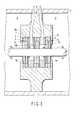
- FIG. 3 is an axial cross-sectional view of a liquid-sealing shaft seal apparatus in a rotary electrical machine a third embodiment of according to the present invention.
- Like reference characters are used in the drawing and description for portions identical to those in the first embodiment shown in FIG. 1.
- the brush seals 4c, 4d, and 4e each are formed in the manner that the brush 5 is clamped by the brush clamp 6.
- the brush seals 4c, 4d, and 4e each are formed such that multiple segments circumferentially split are combined into an annular state, and that two arrays are arranged by circumferentially shifting split planes from each other.
- Numeral 7 denotes resin sheet packings each formed of a resin sheet. More specifically, the respective packing 7 is formed such that, similarly as the brush seal, multiple packing segments split in the circumferential direction are combined in an annular state.
- Each of the resin sheet packings 7 is so mounted on axial sidewalls of the respective three-stage brush seals 4c, 4d, and 4e that the split planes of the packing segments are circumferentially shifted with respect to those of the brush seal segments and that an initial gap thereof with the rotation shaft 1 is zero.
- Numerals 8a, 8b denote spacers each inserted in each of axial inbetween portions of the brush seals 4d, 4e and 4c arranged in the three stages in the axial direction.
- Numeral 9 denotes a holding plate, which is fixed with a bolt (not shown) on an axial sidewall of the brush holder 3 to fix the brush seals 4c, 4d, and 4e, the resin sheet packing 7, and the spacers 8a and 8b, which are stored in the brush holder 3, into the brush holder 3.
- Numerals 10a and 10b respectively, denote the cavities as mentioned above, which are provided in respective inbetween portions of the brush seals 4c, 4d and 4e provided in the three stages in the axial direction.
- the cavities 10a, 10b each are a space having an external diameter larger than that of the seal plate for reducing the flow of gas in the periphery of the rotation shaft 1 generated in conjunction with the rotation of the rotation shaft 1.
- the present embodiment of the liquid-sealing shaft seal apparatus in the rotary electrical machine which is constructed as described above, operates as follows. While the liquid in the liquid atmosphere Q is dispersed in the liquid atmosphere space Q in conjunction with the rotation of the rotation shaft 1, the gap is sealed by the brush seal 4c on the side of liquid atmosphere Q. In this case, as in the first embodiment, the amount of the leakage liquid QL leaking from the brush seal 4c on the side of the liquid atmosphere Q into the cavity 10a is reduced to be smaller than in the conventional techniques by the functions of the resin sheet packings 7.
- the gap is sealed by the brush seal 4d on the side of liquid atmosphere R.
- the amount of leakage liquid RL leaking from the brush seal 4d on the side of the liquid atmosphere R into the cavity 10b is reduced to be smaller than in the conventional techniques by the functions of the resin sheet packings 7.
- a pressure higher than that in the liquid atmosphere space R is applied to the cavity 10b through the cavity through-hole 14 from the outside of the rotary electrical machine, a pressure in the reverse direction with respect to the leakage direction of the leakage liquid RL is exerted on the brush seal 4d.
- the leakage liquid RL having leaked through, for example, the gap with the brush 5 constituting the brush seal 4d and the gap between the brush 5 and the rotation shaft 1 is returned to the liquid atmosphere space R. Consequently, the leakage liquid RL is significantly reduced in amount, and does not accumulate in the cavity 10b.
- a cooling fan is provided for intra-machine ventilation, so that the intra-machine pressure is negative with respect to the atmospheric pressure.
- through-holes corresponding to the cavity through-holes 13 and 14 are opened to the atmosphere, so that the pressure is increased, whereby effects equivalent to the case of pressurization can be obtained.
- the cavity through-holes 13 and 14 are either applied with pressure or opened to the atmosphere.
- the brush seals 4c and 4d, respectively are applied with pressure differences in the reverse direction with respect the leakage directions of the leakage liquids QL and RL. Consequently, the respective liquids do not leak through the brush seal 4e into the cavities 10a and 10b, nor do the respective liquids mix into one another. Further, when the cavity through-holes 13 and 14 are opened to the atmosphere, a compressor is not necessary, thereby simplifying the construction and reducing the cost thereof.
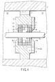
- FIG. 4 is an axial cross-sectional view of a liquid-sealing shaft seal apparatus in a rotary electrical machine according to a fourth embodiment of the present invention.
- Like reference characters are used in the drawing and description for portions identical to those in the first embodiment shown in FIG. 1.
- numeral 1 denotes a rotation shaft
- numeral 2 denotes a frame
- Numeral 3 is a brush holder robustly and hermetically fixed to the frame 2.
- the brush holder 3 is mounted in such a manner as to close a liquid atmosphere space S1 and a non-liquid atmosphere space S2 in the rotary electrical machine.
- two brush seals spaced away from each other via a cavity 10 to be described later are stored. Namely, there are stored two-stage brush seals formed of a brush seal 4a on the side of the liquid atmosphere S1 and a brush seal 4b on the side of the non-liquid atmosphere S2.
- FIG. 1 denotes a rotation shaft
- numeral 2 denotes a frame
- Numeral 3 is a brush holder robustly and hermetically fixed to the frame 2.
- the brush holder 3 is mounted in such a manner as to close a liquid atmosphere space S1 and a non-liquid atmosphere space S2 in the rotary electrical machine.
- the brush seals 4a, 4b are each formed in the manner that the brush 5 is clamped by the brush clamp 6.
- the brush seals 4a, 4b are each formed such that multiple segments circumferentially split are combined into an annular state, and that two arrays are arranged by circumferentially shifting split planes from each other.
- Numeral 7 denotes a resin sheet packing formed of a resin sheet. More specifically, the respective packing 7 is formed such that, similarly as the brush seals 4a, 4b, multiple packing segments split in the circumferential direction are combined in an annular state.
- the resin sheet packing 7 is so mounted on each of axial sidewalls on both sides of the respective two-stage brush seals 4a and 4b that the split planes of the packing segments are circumferentially shifted with respect to those of the brush seal segments and that an initial gap thereof with the rotation shaft 1 is zero.
- Numeral 15 denotes a short brush seal that has a length not contacting the rotation shaft 1.
- the short brush seal 15 is formed such that a short brush clamp 17 clamps the external diameter side of a short brush 16.
- the short brush 16 has a length enabling forming the cavity 10 that serves as a space that reduces the flow of gas in the periphery of the rotation shaft 1 which is generated in conjunction with the rotation of the rotation shaft 1.
- the short brush seal 15 is formed such that multiple segments split in the circumferential direction are combined in an annular state, and is mounted in an axial portion between the brush seals 4a and 4b arranged in the two stages in the axial direction.
- the short brush clamp 17 has multiple holes H in the radial direction.
- Numeral 11 denotes a through-hole to communicate between the same spaces S1 and S2 as in the first embodiment in FIG. 1.
- Numeral 12 is a liquid returning pass that continuously extends through the brush holder 3 and the holding plate 9 from the rear face of the short brush seal 15 to the liquid atmosphere space S1. Also the shapes the brush-holder axial-end bore portion 3a of the brush holder 3 and the bore portion 9a of the holding plate 9 are the same as in the first embodiment shown in FIG. 1.
- the present embodiment of the liquid-sealing shaft seal apparatus in the rotary electrical machine which is constructed as described above, operates as follows. While the liquid in the liquid atmosphere S1 is dispersed in the liquid atmosphere space S1 in conjunction with the rotation of the rotation shaft 1, the gap is sealed by the brush seal 4a on the side of liquid atmosphere S1. In this case, as in the first embodiment, the amount of leakage liquid leaking from the brush seal 4a on the side of the liquid atmosphere S1 into the cavity 10 is reduced to be smaller than in the conventional techniques by the functions of the resin sheet packings 7 and the shape of the bore portion 9a of the holding plate 9. In addition, most of the liquid having leaked to the cavity 10 is captured by the short brush 16, and permeates into the short brush 16 through capillarity or capillary action.
- the short brush 16 has a length not contacting the rotation shaft 1.
- the liquid permeated in the short brush 16 is directed under gravity to flow downward along the short brush clamp 17, and then is returned to the liquid atmosphere space S1 through the liquid returning pass 12 from the holes H in the radial direction provided in the short brush clamp 17. Consequently, the liquid leaking through the brush seal 4b into the non-liquid atmosphere space S2 is significantly reduced.
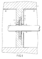
- FIG. 5 is an axial cross-sectional view of a liquid-sealing shaft seal apparatus in a rotary electrical machine according to a fifth embodiment of the present invention.
- Like reference characters are used in the drawing and description for portions identical to those in the first embodiment shown in FIG. 1.
- numeral 1 denotes a rotation shaft
- numeral 2 denotes a frame
- Numeral 3 is a brush holder robustly and hermetically fixed to the frame 2.
- the brush holder 3 is mounted in such a manner as to close a liquid atmosphere space S1 and a non-liquid atmosphere space S2 in the rotary electrical machine.
- two brush seals spaced away from each other via a cavity 10 to be described later are stored. Namely, there are stored two-stage brush seals formed of a brush seal 4a on the side of the liquid atmosphere S1 and a brush seal 4b on the side of the non-liquid atmosphere S2.
- FIG. 1 denotes a rotation shaft
- numeral 2 denotes a frame
- Numeral 3 is a brush holder robustly and hermetically fixed to the frame 2.
- the brush holder 3 is mounted in such a manner as to close a liquid atmosphere space S1 and a non-liquid atmosphere space S2 in the rotary electrical machine.
- the brush seals 4a, 4b are each formed in the manner that the brush 5 is clamped by the brush clamp 6.
- the brush seals 4a, 4b are each formed such that multiple segments circumferentially split are combined into an annular state, and that two arrays are arranged by circumferentially shifting split planes from each other.
- Numeral 7 denotes a resin sheet packing formed of a resin sheet. More specifically, the respective packing 7 is formed such that, similarly as the brush seals 4a, 4b, multiple packing segments split in the circumferential direction are combined in an annular state.
- the resin sheet packing 7 is so mounted on each of axial sidewalls on both sides of the respective two-stage brush seals 4a and 4b that the split planes of the packing segments are circumferentially shifted with respect to those of the brush seal segments and that an initial gap thereof with the rotation shaft 1 is zero.
- Numeral 18 denotes a spacer formed of a porous material, and is inserted between the brush seals 4a and 4b arranged in two stages in the axial direction.
- Numeral 9 denotes the same holding plate as that shown in FIG. 1.
- Numeral 10 denotes the cavity as described above, which has an external diameter larger than that of the seal plane for reducing the flow of gas in the periphery of the rotation shaft 1 generated with the rotation of the rotation shaft 1 in a space surrounded by the resin sheet packings 7, which is defined by the sidewalls of the brush seal, the rotation shaft 1, and the porous spacer 18.
- Numeral 11 denotes the same through-hole as that in the first embodiment shown in FIG. 1.
- Numeral 12 is the same liquid returning pass as that in the fourth embodiment shown in FIG. 4, and a porous material 19 is filled therein.
- the present embodiment of the liquid-sealing shaft seal apparatus in the rotary electrical machine which is constructed as described above, operates as follows. While the liquid in the liquid atmosphere S1 is dispersed in the liquid atmosphere space S1 in conjunction with the rotation of the rotation shaft 1, the gap is sealed by the brush seal 4a on the side of liquid atmosphere S1. In this case, as in the first embodiment, the amount of the leakage liquid QL leaking from the brush seal 4a on the side of the liquid atmosphere S1 into the cavity 10 is reduced to be smaller than in the conventional techniques by the functions of the resin sheet packings 7 and the shape of the bore portion 9a of the holding plate 9. In addition, most of the liquid having leaked into the cavity 10 is captured by the porous spacer 18 arranged on the side of the external diameter of the cavity 10.
- the liquid thus captured is directed under gravity to flow downward through the interior of the porous spacer 18, and then is returned to the liquid atmosphere space S1 through the porous filler material 19 filled into the liquid returning pass 12 arranged below the cavity 10. Consequently, the amount of liquid leaking through the brush seal 4b into the non-liquid atmosphere space S2 is significantly reduced.
Landscapes
- Engineering & Computer Science (AREA)
- General Engineering & Computer Science (AREA)
- Mechanical Engineering (AREA)
- Sealing Devices (AREA)
- Motor Or Generator Frames (AREA)
- Sealing Using Fluids, Sealing Without Contact, And Removal Of Oil (AREA)
- Turbine Rotor Nozzle Sealing (AREA)
Applications Claiming Priority (1)
| Application Number | Priority Date | Filing Date | Title |
|---|---|---|---|
| JP2005051432A JP4776249B2 (ja) | 2005-02-25 | 2005-02-25 | 液体の軸封装置とその軸封装置を用いた回転電機 |
Publications (2)
| Publication Number | Publication Date |
|---|---|
| EP1696155A2 true EP1696155A2 (de) | 2006-08-30 |
| EP1696155A3 EP1696155A3 (de) | 2006-11-02 |
Family
ID=36587406
Family Applications (1)
| Application Number | Title | Priority Date | Filing Date |
|---|---|---|---|
| EP06110093A Withdrawn EP1696155A3 (de) | 2005-02-25 | 2006-02-17 | Bürstendichtunganordnung |
Country Status (4)
| Country | Link |
|---|---|
| US (1) | US20060192343A1 (de) |
| EP (1) | EP1696155A3 (de) |
| JP (1) | JP4776249B2 (de) |
| ZA (1) | ZA200601497B (de) |
Cited By (3)
| Publication number | Priority date | Publication date | Assignee | Title |
|---|---|---|---|---|
| WO2008138713A1 (de) * | 2007-05-09 | 2008-11-20 | Siemens Aktiengesellschaft | Wellendichtung für dampfturbinen |
| WO2015128584A1 (fr) * | 2014-02-28 | 2015-09-03 | Snecma | Réduction du débit de fuite d'un joint a brosse par obstruction geometrique flexible |
| CN110219703A (zh) * | 2019-07-09 | 2019-09-10 | 大连保税区华鸿工业技术有限公司 | 大型转机危险气体液压密封装置 |
Families Citing this family (7)
| Publication number | Priority date | Publication date | Assignee | Title |
|---|---|---|---|---|
| US7458584B2 (en) * | 2007-02-27 | 2008-12-02 | United Technologies Corporation | Reverse flow tolerant brush seal |
| DE102007032889A1 (de) * | 2007-07-14 | 2009-01-15 | Mtu Aero Engines Gmbh | Dichtungsvorrichtung für eine Kühlmittelzufuhr an einer rotierenden Spindel sowie Werkkzeugmaschine mit einer derartigen Dichtungsvorrichtung |
| US8028996B2 (en) * | 2008-04-04 | 2011-10-04 | General Electric Company | System and method for adjusting stiffness of a brush sealing system |
| US8146922B2 (en) * | 2008-06-25 | 2012-04-03 | Dresser-Rand Company | Shaft isolation seal |
| US8360982B2 (en) * | 2008-12-05 | 2013-01-29 | General Electric Company | Method and apparatus for operating a micromotor in a fluid using a moisture barrier |
| US8974201B2 (en) * | 2012-02-23 | 2015-03-10 | Ge Oil & Gas Compression Systems, Llc | Rotating compressor valve |
| JP5851890B2 (ja) * | 2012-03-08 | 2016-02-03 | 三菱重工業株式会社 | 軸シール装置 |
Citations (2)
| Publication number | Priority date | Publication date | Assignee | Title |
|---|---|---|---|---|
| EP1070888A2 (de) | 1999-07-22 | 2001-01-24 | General Electric Company | Bürstendichtung und Maschine mit einer Bürstendichtung |
| EP1215422A2 (de) | 2000-12-15 | 2002-06-19 | General Electric Company | Bürstendichtung für eine Lagerbohrung |
Family Cites Families (33)
| Publication number | Priority date | Publication date | Assignee | Title |
|---|---|---|---|---|
| JPS463140Y1 (de) * | 1967-04-12 | 1971-02-03 | ||
| US4156342A (en) * | 1976-06-11 | 1979-05-29 | Westinghouse Canada Limited | Cooling apparatus for a bearing in a gas turbine |
| US4193603A (en) * | 1978-12-21 | 1980-03-18 | Carrier Corporation | Sealing system for a turbomachine |
| GB2198195B (en) * | 1986-12-06 | 1990-05-16 | Rolls Royce Plc | Brush seal |
| GB8712681D0 (en) * | 1987-05-29 | 1987-07-01 | Cross Mfg Co 1938 Ltd | Brush seals |
| DE3812533A1 (de) * | 1988-04-15 | 1989-10-26 | Josef Seelen | Abdichtung fuer blasrohr oder welle |
| GB2250789B (en) * | 1990-12-12 | 1994-03-30 | Rolls Royce Plc | Brush seal arrangement |
| GB9103459D0 (en) * | 1991-02-19 | 1991-04-03 | Cross Mfg Co | Brush seal assembly |
| US5758879A (en) * | 1991-08-01 | 1998-06-02 | Cross Manufacturing Company (1938) Limited | Brush seal assembly |
| US5201530A (en) * | 1991-10-18 | 1993-04-13 | United Technologies Corporation | Multi-layered brush seal |
| US5318309A (en) * | 1992-05-11 | 1994-06-07 | General Electric Company | Brush seal |
| EP0577908B1 (de) * | 1992-07-10 | 1995-09-06 | Ansaldo Energia S.P.A. | Verfahren zur Abdichtung des Rotors einer geothermischen Nassdampfturbine |
| US5351971A (en) * | 1993-05-21 | 1994-10-04 | Eg&G Sealol, Inc. | Brush seal device having a floating backplate |
| GB9525212D0 (en) * | 1995-12-09 | 1996-02-07 | Rolls Royce Plc | Brush seal |
| US5884918A (en) * | 1996-10-04 | 1999-03-23 | Eg&G Sealol, Inc. | Brush seal with a flexible front plate |
| US6032959A (en) * | 1997-07-21 | 2000-03-07 | General Electric Company | Shingle damper brush seal |
| US6000701A (en) * | 1997-12-15 | 1999-12-14 | Dresser-Rand Company | Labyrinth seal assembly and method |
| GB9821927D0 (en) * | 1998-10-08 | 1998-12-02 | Rolls Royce Plc | Improved brush seal |
| US6416057B1 (en) * | 1999-04-16 | 2002-07-09 | Flowserve Management Company | Brush seal |
| US6250879B1 (en) * | 1999-10-15 | 2001-06-26 | General Electric Company | Brush seal |
| US6330790B1 (en) * | 1999-10-27 | 2001-12-18 | Alliedsignal, Inc. | Oil sump buffer seal |
| US6378873B1 (en) * | 2000-06-02 | 2002-04-30 | General Electric Company | Low flow fluid film seal for hydrogen cooled generators |
| US6431827B1 (en) * | 2000-12-21 | 2002-08-13 | General Electric Company | Bucket tip brush seals in steam turbines and methods of installation |
| US7677847B2 (en) * | 2002-03-26 | 2010-03-16 | Siemens Aktiengesellschaft | Sealing assembly for a spindle |
| US7052015B2 (en) * | 2002-08-06 | 2006-05-30 | United Technologies Corporation | Cooling arrangement for brush seal |
| US6854735B2 (en) * | 2002-08-26 | 2005-02-15 | General Electric Company | In situ load sharing brush seals |
| US6827350B2 (en) * | 2002-10-30 | 2004-12-07 | General Electric Company | Hybrid honeycomb and brush seal for steam gland |
| JPWO2004044465A1 (ja) * | 2002-11-13 | 2006-03-16 | 株式会社東芝 | 回転電機 |
| US7270333B2 (en) * | 2002-11-27 | 2007-09-18 | United Technologies Corporation | Brush seal with adjustable clearance |
| DE10324709A1 (de) * | 2003-05-30 | 2004-12-16 | Mtu Aero Engines Gmbh | Bürstendichtung zum Abdichten relativ zueinander beweglicher Bauteile gegenüber einem Druckgefälle |
| US20040256807A1 (en) * | 2003-06-23 | 2004-12-23 | Nitin Bhate | Retrofittable non-metallic brush seal assembly |
| US6976679B2 (en) * | 2003-11-07 | 2005-12-20 | The Boeing Company | Inter-fluid seal assembly and method therefor |
| US6991235B2 (en) * | 2003-11-07 | 2006-01-31 | The Boeing Company | Gas-buffered seal assembly and method therefor |
-
2005
- 2005-02-25 JP JP2005051432A patent/JP4776249B2/ja not_active Expired - Fee Related
-
2006
- 2006-02-17 US US11/355,881 patent/US20060192343A1/en not_active Abandoned
- 2006-02-17 EP EP06110093A patent/EP1696155A3/de not_active Withdrawn
- 2006-02-21 ZA ZA200601497A patent/ZA200601497B/xx unknown
Patent Citations (2)
| Publication number | Priority date | Publication date | Assignee | Title |
|---|---|---|---|---|
| EP1070888A2 (de) | 1999-07-22 | 2001-01-24 | General Electric Company | Bürstendichtung und Maschine mit einer Bürstendichtung |
| EP1215422A2 (de) | 2000-12-15 | 2002-06-19 | General Electric Company | Bürstendichtung für eine Lagerbohrung |
Cited By (8)
| Publication number | Priority date | Publication date | Assignee | Title |
|---|---|---|---|---|
| WO2008138713A1 (de) * | 2007-05-09 | 2008-11-20 | Siemens Aktiengesellschaft | Wellendichtung für dampfturbinen |
| CN101680307B (zh) * | 2007-05-09 | 2013-10-16 | 西门子公司 | 用于蒸汽透平的轴密封装置 |
| US9175775B2 (en) | 2007-05-09 | 2015-11-03 | Siemens Aktiengesellschaft | Shaft seal for steam turbines |
| WO2015128584A1 (fr) * | 2014-02-28 | 2015-09-03 | Snecma | Réduction du débit de fuite d'un joint a brosse par obstruction geometrique flexible |
| FR3018109A1 (fr) * | 2014-02-28 | 2015-09-04 | Snecma | Reduction du debit de fuite d'un joint a brosse par obstruction geometrique flexible |
| US10458550B2 (en) | 2014-02-28 | 2019-10-29 | Safran Aircraft Engines | Reduction in the leakage flow rate of a brush seal by flexible geometric obstruction |
| CN110219703A (zh) * | 2019-07-09 | 2019-09-10 | 大连保税区华鸿工业技术有限公司 | 大型转机危险气体液压密封装置 |
| CN110219703B (zh) * | 2019-07-09 | 2024-02-09 | 大连保税区华鸿工业技术有限公司 | 大型转机危险气体液压密封装置 |
Also Published As
| Publication number | Publication date |
|---|---|
| EP1696155A3 (de) | 2006-11-02 |
| JP2006234106A (ja) | 2006-09-07 |
| US20060192343A1 (en) | 2006-08-31 |
| JP4776249B2 (ja) | 2011-09-21 |
| ZA200601497B (en) | 2007-04-25 |
Similar Documents
| Publication | Publication Date | Title |
|---|---|---|
| US6428014B2 (en) | Piston sealing ring assembly | |
| AU667384B2 (en) | Gas lubricated barrier seal | |
| EP1696155A2 (de) | Bürstendichtunganordnung | |
| US20220235772A1 (en) | Vacuum pumping system having an oil-lubricated vacuum pump | |
| US9004491B2 (en) | Shaft seal assembly | |
| EP0180635A1 (de) | Abdichtung mit magnetischem fluidum für hin- und hergehende teile | |
| JP4824552B2 (ja) | 静的および動的な排出機の耐圧シャフトシール | |
| CN212202588U (zh) | 具有冷却结构的泵用双端面密封 | |
| JP2026511645A (ja) | 乾式真空ポンプ及び回転機械に用いる油封・気密シール装置 | |
| CN101046254B (zh) | 转动轴密封件 | |
| JP2002122087A (ja) | 真空ポンプにおける軸封構造 | |
| JPH0561473B2 (de) | ||
| EP0136617B1 (de) | Doppeldichtungsanordnung für Roots Gebläse | |
| JPH0389080A (ja) | 真空ポンプ潤滑油のシール機構 | |
| JP5092036B2 (ja) | 液体の軸封装置とその軸封装置を用いた回転電機 | |
| GB2140102A (en) | Improvements in shaft seals | |
| JP2000279783A (ja) | 回転機器の軸封装置 | |
| CN223203970U (zh) | 一种双介质旋转接头 | |
| US20150219221A1 (en) | Non-contact split seal | |
| JP4566159B2 (ja) | 多流路形ロータリジョイント | |
| JPS61126390A (ja) | オイルフリ−スクロ−ル形流体機械 | |
| CN110792598A (zh) | 一种罗茨泵内轴封之机械密封 | |
| JPH0635737U (ja) | 軸の真空シール構造 | |
| JPS61132797A (ja) | タ−ボ分子ポンプの軸受装置 | |
| WO1997020145A1 (en) | Axial sealing |
Legal Events
| Date | Code | Title | Description |
|---|---|---|---|
| PUAI | Public reference made under article 153(3) epc to a published international application that has entered the european phase |
Free format text: ORIGINAL CODE: 0009012 |
|
| 17P | Request for examination filed |
Effective date: 20060220 |
|
| AK | Designated contracting states |
Kind code of ref document: A2 Designated state(s): AT BE BG CH CY CZ DE DK EE ES FI FR GB GR HU IE IS IT LI LT LU LV MC NL PL PT RO SE SI SK TR |
|
| AX | Request for extension of the european patent |
Extension state: AL BA HR MK YU |
|
| PUAL | Search report despatched |
Free format text: ORIGINAL CODE: 0009013 |
|
| AK | Designated contracting states |
Kind code of ref document: A3 Designated state(s): AT BE BG CH CY CZ DE DK EE ES FI FR GB GR HU IE IS IT LI LT LU LV MC NL PL PT RO SE SI SK TR |
|
| AX | Request for extension of the european patent |
Extension state: AL BA HR MK YU |
|
| 17Q | First examination report despatched |
Effective date: 20061215 |
|
| AKX | Designation fees paid |
Designated state(s): GB |
|
| REG | Reference to a national code |
Ref country code: DE Ref legal event code: 8566 |
|
| STAA | Information on the status of an ep patent application or granted ep patent |
Free format text: STATUS: THE APPLICATION IS DEEMED TO BE WITHDRAWN |
|
| 18D | Application deemed to be withdrawn |
Effective date: 20170307 |