EP1696157A2 - Ventil - Google Patents
Ventil Download PDFInfo
- Publication number
- EP1696157A2 EP1696157A2 EP06290227A EP06290227A EP1696157A2 EP 1696157 A2 EP1696157 A2 EP 1696157A2 EP 06290227 A EP06290227 A EP 06290227A EP 06290227 A EP06290227 A EP 06290227A EP 1696157 A2 EP1696157 A2 EP 1696157A2
- Authority
- EP
- European Patent Office
- Prior art keywords
- groove
- seat
- face
- distance
- cylindrical
- Prior art date
- Legal status (The legal status is an assumption and is not a legal conclusion. Google has not performed a legal analysis and makes no representation as to the accuracy of the status listed.)
- Withdrawn
Links
- 238000007789 sealing Methods 0.000 claims abstract description 25
- 239000012530 fluid Substances 0.000 description 8
- 239000000463 material Substances 0.000 description 4
- 208000031968 Cadaver Diseases 0.000 description 3
- 230000000694 effects Effects 0.000 description 3
- 235000001954 papillon Nutrition 0.000 description 3
- 244000229285 papillon Species 0.000 description 3
- 101100328879 Caenorhabditis elegans col-14 gene Proteins 0.000 description 2
- 230000004888 barrier function Effects 0.000 description 2
- 238000011065 in-situ storage Methods 0.000 description 2
- 238000002347 injection Methods 0.000 description 2
- 239000007924 injection Substances 0.000 description 2
- 230000002093 peripheral effect Effects 0.000 description 2
- 230000003068 static effect Effects 0.000 description 2
- 235000002790 Monstera deliciosa Nutrition 0.000 description 1
- 240000000987 Monstera deliciosa Species 0.000 description 1
- 229920000034 Plastomer Polymers 0.000 description 1
- 230000001154 acute effect Effects 0.000 description 1
- 238000005452 bending Methods 0.000 description 1
- 239000002131 composite material Substances 0.000 description 1
- 239000013536 elastomeric material Substances 0.000 description 1
- 239000003822 epoxy resin Substances 0.000 description 1
- 238000009434 installation Methods 0.000 description 1
- 230000002452 interceptive effect Effects 0.000 description 1
- 238000012423 maintenance Methods 0.000 description 1
- 239000002184 metal Substances 0.000 description 1
- 238000000034 method Methods 0.000 description 1
- 230000035515 penetration Effects 0.000 description 1
- 239000004033 plastic Substances 0.000 description 1
- 229920000647 polyepoxide Polymers 0.000 description 1
- 229920005989 resin Polymers 0.000 description 1
- 239000011347 resin Substances 0.000 description 1
- 238000011144 upstream manufacturing Methods 0.000 description 1
- XLYOFNOQVPJJNP-UHFFFAOYSA-N water Substances O XLYOFNOQVPJJNP-UHFFFAOYSA-N 0.000 description 1
Images


Classifications
-
- F—MECHANICAL ENGINEERING; LIGHTING; HEATING; WEAPONS; BLASTING
- F16—ENGINEERING ELEMENTS AND UNITS; GENERAL MEASURES FOR PRODUCING AND MAINTAINING EFFECTIVE FUNCTIONING OF MACHINES OR INSTALLATIONS; THERMAL INSULATION IN GENERAL
- F16K—VALVES; TAPS; COCKS; ACTUATING-FLOATS; DEVICES FOR VENTING OR AERATING
- F16K1/00—Lift valves or globe valves, i.e. cut-off apparatus with closure members having at least a component of their opening and closing motion perpendicular to the closing faces
- F16K1/16—Lift valves or globe valves, i.e. cut-off apparatus with closure members having at least a component of their opening and closing motion perpendicular to the closing faces with pivoted closure-members
- F16K1/18—Lift valves or globe valves, i.e. cut-off apparatus with closure members having at least a component of their opening and closing motion perpendicular to the closing faces with pivoted closure-members with pivoted discs or flaps
- F16K1/22—Lift valves or globe valves, i.e. cut-off apparatus with closure members having at least a component of their opening and closing motion perpendicular to the closing faces with pivoted closure-members with pivoted discs or flaps with axis of rotation crossing the valve member, e.g. butterfly valves
-
- F—MECHANICAL ENGINEERING; LIGHTING; HEATING; WEAPONS; BLASTING
- F16—ENGINEERING ELEMENTS AND UNITS; GENERAL MEASURES FOR PRODUCING AND MAINTAINING EFFECTIVE FUNCTIONING OF MACHINES OR INSTALLATIONS; THERMAL INSULATION IN GENERAL
- F16K—VALVES; TAPS; COCKS; ACTUATING-FLOATS; DEVICES FOR VENTING OR AERATING
- F16K1/00—Lift valves or globe valves, i.e. cut-off apparatus with closure members having at least a component of their opening and closing motion perpendicular to the closing faces
- F16K1/16—Lift valves or globe valves, i.e. cut-off apparatus with closure members having at least a component of their opening and closing motion perpendicular to the closing faces with pivoted closure-members
- F16K1/18—Lift valves or globe valves, i.e. cut-off apparatus with closure members having at least a component of their opening and closing motion perpendicular to the closing faces with pivoted closure-members with pivoted discs or flaps
- F16K1/22—Lift valves or globe valves, i.e. cut-off apparatus with closure members having at least a component of their opening and closing motion perpendicular to the closing faces with pivoted closure-members with pivoted discs or flaps with axis of rotation crossing the valve member, e.g. butterfly valves
- F16K1/226—Shaping or arrangements of the sealing
- F16K1/2263—Shaping or arrangements of the sealing the sealing being arranged on the valve seat
-
- F—MECHANICAL ENGINEERING; LIGHTING; HEATING; WEAPONS; BLASTING
- F16—ENGINEERING ELEMENTS AND UNITS; GENERAL MEASURES FOR PRODUCING AND MAINTAINING EFFECTIVE FUNCTIONING OF MACHINES OR INSTALLATIONS; THERMAL INSULATION IN GENERAL
- F16K—VALVES; TAPS; COCKS; ACTUATING-FLOATS; DEVICES FOR VENTING OR AERATING
- F16K1/00—Lift valves or globe valves, i.e. cut-off apparatus with closure members having at least a component of their opening and closing motion perpendicular to the closing faces
- F16K1/16—Lift valves or globe valves, i.e. cut-off apparatus with closure members having at least a component of their opening and closing motion perpendicular to the closing faces with pivoted closure-members
- F16K1/18—Lift valves or globe valves, i.e. cut-off apparatus with closure members having at least a component of their opening and closing motion perpendicular to the closing faces with pivoted closure-members with pivoted discs or flaps
- F16K1/22—Lift valves or globe valves, i.e. cut-off apparatus with closure members having at least a component of their opening and closing motion perpendicular to the closing faces with pivoted closure-members with pivoted discs or flaps with axis of rotation crossing the valve member, e.g. butterfly valves
- F16K1/226—Shaping or arrangements of the sealing
- F16K1/2261—Shaping or arrangements of the sealing the sealing being arranged on the valve member
-
- F—MECHANICAL ENGINEERING; LIGHTING; HEATING; WEAPONS; BLASTING
- F16—ENGINEERING ELEMENTS AND UNITS; GENERAL MEASURES FOR PRODUCING AND MAINTAINING EFFECTIVE FUNCTIONING OF MACHINES OR INSTALLATIONS; THERMAL INSULATION IN GENERAL
- F16K—VALVES; TAPS; COCKS; ACTUATING-FLOATS; DEVICES FOR VENTING OR AERATING
- F16K1/00—Lift valves or globe valves, i.e. cut-off apparatus with closure members having at least a component of their opening and closing motion perpendicular to the closing faces
- F16K1/32—Details
- F16K1/34—Cutting-off parts, e.g. valve members, seats
- F16K1/42—Valve seats
-
- F—MECHANICAL ENGINEERING; LIGHTING; HEATING; WEAPONS; BLASTING
- F16—ENGINEERING ELEMENTS AND UNITS; GENERAL MEASURES FOR PRODUCING AND MAINTAINING EFFECTIVE FUNCTIONING OF MACHINES OR INSTALLATIONS; THERMAL INSULATION IN GENERAL
- F16K—VALVES; TAPS; COCKS; ACTUATING-FLOATS; DEVICES FOR VENTING OR AERATING
- F16K1/00—Lift valves or globe valves, i.e. cut-off apparatus with closure members having at least a component of their opening and closing motion perpendicular to the closing faces
- F16K1/32—Details
- F16K1/34—Cutting-off parts, e.g. valve members, seats
- F16K1/46—Attachment of sealing rings
-
- F—MECHANICAL ENGINEERING; LIGHTING; HEATING; WEAPONS; BLASTING
- F16—ENGINEERING ELEMENTS AND UNITS; GENERAL MEASURES FOR PRODUCING AND MAINTAINING EFFECTIVE FUNCTIONING OF MACHINES OR INSTALLATIONS; THERMAL INSULATION IN GENERAL
- F16K—VALVES; TAPS; COCKS; ACTUATING-FLOATS; DEVICES FOR VENTING OR AERATING
- F16K27/00—Construction of housing; Use of materials therefor
- F16K27/02—Construction of housing; Use of materials therefor of lift valves
- F16K27/0209—Check valves or pivoted valves
- F16K27/0218—Butterfly valves
Definitions
- the present invention relates to so-called "butterfly offset" valves.
- the axis of rotation of the disc-shaped butterfly is offset from the plane of the butterfly and is parallel to that plane.
- the axis of rotation is also eccentric with respect to the axis of the pipe.
- Offset butterfly valves have a seat that can be made of a plastomer or elastomeric or composite material.
- This seat makes it possible to perform the upstream / downstream sealing function when the butterfly closes. It cooperates with a sealing surface located on the opposite piece to seal the valve when the latter is closed. This function is achieved by the application of a seat contact pressure / sealing range, greater than the pressure of the fluid carried.
- the seat can be secured to the body or the butterfly.
- This type of valve is preferably used for large pipe diameters and the seat can be removed in situ by an operator without disassembling the valve of the installation.
- the seal is usually attached using a clamp clamped by clamps or a flange applied by screws.
- the seat is sometimes sealed by the injection of a polymerizable resin.
- the clearance between the body and the throttle is small downstream of the seal, (opposite side to the pressure) so that the seal is not extruded in the game under the effect of pressure.
- the seal is disposed in a groove parallel to the plane of the butterfly and therefore the geometry of the interface between the edge of the butterfly and the part opposite to the body is asymmetrical with respect to the plane of symmetry of the seat itself. even. As a result, the behavior and sealing performance of the seat will be different depending on the direction of application of the pressure.
- the invention overcomes this disadvantage by an offset butterfly valve, which has equivalent performance in both directions regardless of the direction of application of the pressure, but which does not leak.
- the valve can have a diameter of up to 3 m and more and provide a seal at pressures between 40 and 63 bar.
- the invention therefore relates to a valve comprising a cylindrical tubular body and a disc-shaped butterfly, rotatably mounted with respect to an axis offset from the plane of the butterfly and parallel to this plane, and a monobloc ring seat reported in a closed annular groove, therefore in a blind hole, on one of the inner face of the body and the edge of the butterfly, the other of them coming by a sealing surface in contact with the seat in a position of closing the valve and moving away in an open position, the seat comprising two projecting lateral parts symmetrical to each other, characterized in that each projecting part is constituted in the form of a lip d sealing, the tapered free edge is brought to the inside of the groove by contact with the side face of the groove and which is directed in the opposite direction to that towards the bottom of the groove.
- Closed groove means a groove having a bottom and not a groove open on both sides or closed on one side by an insert.
- EP-1 284 379 not described a valve providing a seal at least up to 40 bar, but a pneumatic air distributor under relatively low pressure, for example 8 bar.
- a floating sealing device that is self-centered at any time on the spool 25 is described. If it were not so, and if the rubber part was supported, not on a moving element, but in the body of the dispenser , there would constantly be variation of the compressive force as a function of the dynamic bending forces exerted on the spool 25. This would result in leaks and if the compressive force was too great, the solenoid valve ordering the drawer to move may be too small.
- the sealing device is necessarily in two parts. It is more expensive and difficult to mount.
- the inner rubber seal is therefore based on a rigid peripheral ring 26 which, to be free to move in its housing, must have a clearance in the bottom of the groove and laterally.
- the groove has as shoulder only the two shoulders symmetrical to each other so that the groove is substantially T-shaped and is easy to machine.
- a multiple shouldered groove as shown in Figure 4 of US 6,494,466 is so complicated to machine that it industrially condemns such a valve.
- the seat has a V-shaped groove, the tip of which is turned towards the bottom of the groove, and a plurality of V-shaped elastic clips are distributed along the groove.
- the imaginary extension of the branches of the V intersects the shoulder.
- the staples which are for example made of metal or a plastic material having elasticity, thus push the material of the seat towards the walls of the groove and the branches of the V oppose the expulsion of the seat out of the throat by buttresses on the shoulders.
- the invention also relates to a seat made of a plastomeric or preferably an elastomeric ring material having a cylindrical inner (outer) face and an outer (inner) ring face comprising two lobes, characterized by two lips with tapered free edges, the distance counted parallel to the axis of symmetry of the seat, between the cylindrical face and the lips being smaller than the distance between the cylindrical face and the lobes.
- the inner face is cylindrical and the outer face is toric.
- the outer face is cylindrical and the inner face is toric.
- the seat has a V-groove opening on the cylindrical face.
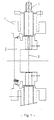
- the butterfly valve offset according to the invention is mounted in Figure 1 between two flanges of a pipe.
- the valve essentially comprises a cylindrical tubular body 1 and a disc-shaped butterfly 2 mounted to rotate relative to an axis 3 offset from the plane of the butterfly and parallel to this plane.
- An actuator 4 of the valve makes it possible to turn the butterfly with respect to the axis 3.
- This axis 3 is also off-center with respect to the axis of the pipework.
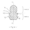
- a seat 5 of a single ring-shaped shape that is best seen in Figures 2 to 8.
- a current embodiment In the lower part of Figure 1 (opposite the actuator ) is shown a current embodiment, while at the upper part (actuator side) is shown an embodiment according to the invention.
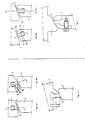
- Figures 2 and 3 show the detail of current embodiments with auxiliary fasteners of the seat respectively on the body and on the edge of the butterfly.
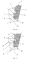
- FIG. 4a shows a disposition where the plane XX 'of symmetry of the seat is inclined with respect to the bearing surface 10 of the butterfly and FIG. 4b the optimal position where the plane XX' of symmetry of the seat is perpendicular to the bearing surface 10 of seal.
- FIG. 9 is a cross-sectional view of a seat according to the invention.
- This seat comprises a cylindrical inner face 18 and an outer ring face 19 at least in part, it comprises, from top to bottom according to FIG. 9, an upper part 20 followed by two lateral lobes 21 projecting defined by a face 22 perpendicular to the axis XX 'of symmetry of the seat, the face 22 being followed, along a bend at right angles to a face 23 parallel to the axis XX' and the latter being followed in turn by a face 24 inclined to about 45 degrees and re-entering.
- This face 24 defines with a next face 25 after a rounded portion 26, a groove.
- the seat being symmetrical about the axis XX ', there are two grooves symmetrical to each other with respect to this axis.
- On the face 25 follows a face 27 intersecting with the face 25 at an acute angle 28 providing a tip in cross section.
- the faces 25 and 27 thus define a flexible and tapered lip.
- the two points 28 define between them the largest width of the seat.
- a face 29 which defines a base portion of the seat defining itself the cylindrical bearing face 18 at the bottom of the groove.
- this face 18 opens a groove 30 in V, the imaginary extensions of the directions of the branches 31 of the V cutting the faces 22.
- V-shaped elastic clips 32 In this groove 30 are arranged equidistantly V-shaped elastic clips 32, as shown in Figure 10, which tend to push in particular the material of the seat between the faces 22, 23 and 24 to the outside.
- this short lip plays the same role as the lip 8 or 25, 27, 28 on which the pressure forces P2 are exerted.
- the short lip is designed to interfere with the wall of the throat which folds it slightly by creating a concavity outwardly of the throat.
- the short lip thus acts as a first sealing barrier to which the lip 8 or 25, 27, 28 will be subjected in the event of functional insufficiency.
- the short lip also acts autoclave, that is to say, as the pressure increases, the better the seal.
- the dynamic portion of the seat that is in contact with the opposite piece is a torus portion.
- this torus portion is extended by two elements 33 which are tangent and which form bulges.
- the dimension of the width l of the seat in the free state taken at the top of the bulges is therefore greater than the corresponding dimension of the groove.
Landscapes
- Engineering & Computer Science (AREA)
- General Engineering & Computer Science (AREA)
- Mechanical Engineering (AREA)
- Lift Valve (AREA)
- Sealing Devices (AREA)
- Gasket Seals (AREA)
- Closures For Containers (AREA)
Applications Claiming Priority (1)
| Application Number | Priority Date | Filing Date | Title |
|---|---|---|---|
| FR0501941A FR2882585B1 (fr) | 2005-02-25 | 2005-02-25 | Robinet a siege a levres |
Publications (2)
| Publication Number | Publication Date |
|---|---|
| EP1696157A2 true EP1696157A2 (de) | 2006-08-30 |
| EP1696157A3 EP1696157A3 (de) | 2017-09-20 |
Family
ID=34982385
Family Applications (1)
| Application Number | Title | Priority Date | Filing Date |
|---|---|---|---|
| EP06290227.5A Withdrawn EP1696157A3 (de) | 2005-02-25 | 2006-02-09 | Ventil |
Country Status (5)
| Country | Link |
|---|---|
| EP (1) | EP1696157A3 (de) |
| JP (1) | JP5021941B2 (de) |
| KR (1) | KR20060094863A (de) |
| CN (1) | CN1828101B (de) |
| FR (1) | FR2882585B1 (de) |
Cited By (2)
| Publication number | Priority date | Publication date | Assignee | Title |
|---|---|---|---|---|
| WO2013088002A1 (fr) * | 2011-12-14 | 2013-06-20 | Ksb S.A.S. | Robinet a papillon |
| WO2013124546A1 (fr) | 2012-02-21 | 2013-08-29 | Ksb S.A.S. | Robinet a papillon |
Families Citing this family (8)
| Publication number | Priority date | Publication date | Assignee | Title |
|---|---|---|---|---|
| JP4224862B2 (ja) | 2006-10-12 | 2009-02-18 | Smc株式会社 | バルブ装置 |
| US8466335B2 (en) * | 2010-04-26 | 2013-06-18 | The Procter & Gamble Company | Personal care product |
| JP6203504B2 (ja) * | 2013-02-18 | 2017-09-27 | コスモ工機株式会社 | 分岐装置 |
| CN103470792A (zh) * | 2013-09-23 | 2013-12-25 | 南通龙源电站阀门有限公司 | 三偏心可在线更换阀座的高压蝶阀 |
| JP6371890B2 (ja) * | 2017-08-03 | 2018-08-08 | コスモ工機株式会社 | 分岐装置 |
| CN110005827A (zh) * | 2019-01-22 | 2019-07-12 | 江苏远望仪器集团有限公司 | 应用于管道中的蝶阀唇型贴密封结构 |
| JP7147710B2 (ja) * | 2019-08-01 | 2022-10-05 | 株式会社デンソー | シールリング、弁装置 |
| KR102296760B1 (ko) * | 2021-01-06 | 2021-09-03 | 주식회사 피엔케이이엔지 | 컨트롤 밸브용 시트 및 이를 포함하는 컨트롤 밸브 |
Citations (2)
| Publication number | Priority date | Publication date | Assignee | Title |
|---|---|---|---|---|
| US6494466B1 (en) | 2000-04-20 | 2002-12-17 | Thomas A. Hartman | Valve seal construction with non-congruent side serrations |
| EP1284379A1 (de) | 2001-08-11 | 2003-02-19 | Robert Bosch Gmbh | Dichtungsanordnung für ein pneumatisches Wegeventil |
Family Cites Families (8)
| Publication number | Priority date | Publication date | Assignee | Title |
|---|---|---|---|---|
| GB1301099A (en) * | 1969-04-16 | 1972-12-29 | British Ropes Ltd | Valved piping |
| US3799501A (en) * | 1971-12-27 | 1974-03-26 | T Hartman | Elastomers in shear force transfer systems |
| CA1017314A (en) * | 1973-12-05 | 1977-09-13 | Werner K. Priese | Pressure loaded sealing arrangement |
| AT399545B (de) * | 1993-05-05 | 1995-05-26 | Hoerbiger Ventilwerke Ag | Dichtungsanordnung |
| JPH10267141A (ja) * | 1997-03-21 | 1998-10-09 | Smc Corp | スプール |
| JP2000320692A (ja) * | 1999-05-12 | 2000-11-24 | Maezawa Ind Inc | バタフライ弁及びその弁座取付方法 |
| JP2001041328A (ja) * | 1999-06-09 | 2001-02-13 | Nippon Carbon Co Ltd | 弁棒の取り付け位置を弁体中央部から5%以上離し偏心させたバタフライ弁 |
| JP4375522B2 (ja) * | 2002-11-28 | 2009-12-02 | Nok株式会社 | 蟻溝用シールリング |
-
2005
- 2005-02-25 FR FR0501941A patent/FR2882585B1/fr not_active Expired - Fee Related
-
2006
- 2006-02-02 KR KR1020060010212A patent/KR20060094863A/ko not_active Ceased
- 2006-02-09 EP EP06290227.5A patent/EP1696157A3/de not_active Withdrawn
- 2006-02-15 CN CN2006100549033A patent/CN1828101B/zh not_active Expired - Fee Related
- 2006-02-23 JP JP2006047507A patent/JP5021941B2/ja not_active Expired - Fee Related
Patent Citations (2)
| Publication number | Priority date | Publication date | Assignee | Title |
|---|---|---|---|---|
| US6494466B1 (en) | 2000-04-20 | 2002-12-17 | Thomas A. Hartman | Valve seal construction with non-congruent side serrations |
| EP1284379A1 (de) | 2001-08-11 | 2003-02-19 | Robert Bosch Gmbh | Dichtungsanordnung für ein pneumatisches Wegeventil |
Cited By (3)
| Publication number | Priority date | Publication date | Assignee | Title |
|---|---|---|---|---|
| WO2013088002A1 (fr) * | 2011-12-14 | 2013-06-20 | Ksb S.A.S. | Robinet a papillon |
| FR2984446A1 (fr) * | 2011-12-14 | 2013-06-21 | Ksb Sas | Robinet a papillon |
| WO2013124546A1 (fr) | 2012-02-21 | 2013-08-29 | Ksb S.A.S. | Robinet a papillon |
Also Published As
| Publication number | Publication date |
|---|---|
| JP5021941B2 (ja) | 2012-09-12 |
| EP1696157A3 (de) | 2017-09-20 |
| FR2882585A1 (fr) | 2006-09-01 |
| CN1828101B (zh) | 2010-06-09 |
| FR2882585B1 (fr) | 2008-10-10 |
| KR20060094863A (ko) | 2006-08-30 |
| CN1828101A (zh) | 2006-09-06 |
| JP2006234168A (ja) | 2006-09-07 |
Similar Documents
| Publication | Publication Date | Title |
|---|---|---|
| EP1696157A2 (de) | Ventil | |
| EP1780427B1 (de) | Nicht einschneidende Verankerungsscheibe | |
| EP1792110A1 (de) | Stopfbuchsendichtung und entsprechende anordnung | |
| CA2891814C (fr) | Jonction tubulaire | |
| EP1696156A2 (de) | Klappenventil | |
| FR3124566A1 (fr) | Dispositif de raccordement fluidique et vanne inserable anti-retour pour vehicule | |
| FR3072150A1 (fr) | Joint d'etancheite | |
| FR3124567A1 (fr) | Dispositif de raccordement fluidique et vanne inserable anti-retour pour vehicule | |
| FR2892491A1 (fr) | Dispositif de raccordement a corps soude | |
| EP3642515B1 (de) | Zentrische absperrklappe | |
| EP1554513B2 (de) | Absperrschieber | |
| FR2916657A1 (fr) | Dispositif d'obturation d'une buse de distribution de fluide | |
| FR2512917A1 (fr) | Garniture d'etancheite pour joint de canalisation | |
| CH696598A5 (fr) | Bride étanche contre les fuites pour raccorder des tuyaux ayant des diamètres extérieurs différents et des extrémités lisses. | |
| EP0202156A1 (de) | Ringförmige Dichtungsanordnung, insbesondere für Klappen oder Ventile | |
| FR2987094A1 (fr) | Robinet a papillon | |
| FR2640679A1 (fr) | Tube d'injection pour colonne articulee de forage a injection d'eau | |
| FR2990010A1 (fr) | Organe de fixation d'un accessoire sur un support ainsi que du support sur une structure | |
| FR2673263A1 (fr) | Ensemble formant joint pour raccordement souple entre deux elements. | |
| EP1619437A1 (de) | Verbindung einer Abzweigung | |
| FR2610693A1 (fr) | Dispositif d'etancheite pour des soupapes | |
| EP3985295A1 (de) | Fluidverbindung vom typ patrone | |
| FR2878306A1 (fr) | Procede de fabrication d'un element d'etancheite, element d'etancheite et embase de raccordement correspondants | |
| FR2901861A1 (fr) | Piece de raccordement entre la chambre basse pression d'un amplicateur de frein et la ligne de depression d'un circuit de vide, procede de montage et element liaison a la chambre | |
| EP0811519A1 (de) | Kraftstofftank aus Kunststoff und Dichtring |
Legal Events
| Date | Code | Title | Description |
|---|---|---|---|
| PUAI | Public reference made under article 153(3) epc to a published international application that has entered the european phase |
Free format text: ORIGINAL CODE: 0009012 |
|
| AK | Designated contracting states |
Kind code of ref document: A2 Designated state(s): AT BE BG CH CY CZ DE DK EE ES FI FR GB GR HU IE IS IT LI LT LU LV MC NL PL PT RO SE SI SK TR |
|
| AX | Request for extension of the european patent |
Extension state: AL BA HR MK YU |
|
| PUAL | Search report despatched |
Free format text: ORIGINAL CODE: 0009013 |
|
| AK | Designated contracting states |
Kind code of ref document: A3 Designated state(s): AT BE BG CH CY CZ DE DK EE ES FI FR GB GR HU IE IS IT LI LT LU LV MC NL PL PT RO SE SI SK TR |
|
| AX | Request for extension of the european patent |
Extension state: AL BA HR MK YU |
|
| RIC1 | Information provided on ipc code assigned before grant |
Ipc: F16K 1/226 20060101AFI20170814BHEP |
|
| AKY | No designation fees paid | ||
| AXX | Extension fees paid |
Extension state: YU Extension state: AL Extension state: MK Extension state: BA Extension state: HR |
|
| REG | Reference to a national code |
Ref country code: DE Ref legal event code: R108 |
|
| STAA | Information on the status of an ep patent application or granted ep patent |
Free format text: STATUS: THE APPLICATION IS DEEMED TO BE WITHDRAWN |
|
| 18D | Application deemed to be withdrawn |
Effective date: 20180321 |