EP1696245A2 - Procédé destiné à la localisation d'une plaquette de détection - Google Patents
Procédé destiné à la localisation d'une plaquette de détection Download PDFInfo
- Publication number
- EP1696245A2 EP1696245A2 EP05024992A EP05024992A EP1696245A2 EP 1696245 A2 EP1696245 A2 EP 1696245A2 EP 05024992 A EP05024992 A EP 05024992A EP 05024992 A EP05024992 A EP 05024992A EP 1696245 A2 EP1696245 A2 EP 1696245A2
- Authority
- EP
- European Patent Office
- Prior art keywords
- signal
- detection
- determined
- phase
- distance
- Prior art date
- Legal status (The legal status is an assumption and is not a legal conclusion. Google has not performed a legal analysis and makes no representation as to the accuracy of the status listed.)
- Withdrawn
Links
Images
Classifications
-
- G—PHYSICS
- G01—MEASURING; TESTING
- G01S—RADIO DIRECTION-FINDING; RADIO NAVIGATION; DETERMINING DISTANCE OR VELOCITY BY USE OF RADIO WAVES; LOCATING OR PRESENCE-DETECTING BY USE OF THE REFLECTION OR RERADIATION OF RADIO WAVES; ANALOGOUS ARRANGEMENTS USING OTHER WAVES
- G01S13/00—Systems using the reflection or reradiation of radio waves, e.g. radar systems; Analogous systems using reflection or reradiation of waves whose nature or wavelength is irrelevant or unspecified
- G01S13/74—Systems using reradiation of radio waves, e.g. secondary radar systems; Analogous systems
- G01S13/82—Systems using reradiation of radio waves, e.g. secondary radar systems; Analogous systems wherein continuous-type signals are transmitted
- G01S13/84—Systems using reradiation of radio waves, e.g. secondary radar systems; Analogous systems wherein continuous-type signals are transmitted for distance determination by phase measurement
-
- G—PHYSICS
- G01—MEASURING; TESTING
- G01S—RADIO DIRECTION-FINDING; RADIO NAVIGATION; DETERMINING DISTANCE OR VELOCITY BY USE OF RADIO WAVES; LOCATING OR PRESENCE-DETECTING BY USE OF THE REFLECTION OR RERADIATION OF RADIO WAVES; ANALOGOUS ARRANGEMENTS USING OTHER WAVES
- G01S13/00—Systems using the reflection or reradiation of radio waves, e.g. radar systems; Analogous systems using reflection or reradiation of waves whose nature or wavelength is irrelevant or unspecified
- G01S13/74—Systems using reradiation of radio waves, e.g. secondary radar systems; Analogous systems
- G01S13/75—Systems using reradiation of radio waves, e.g. secondary radar systems; Analogous systems using transponders powered from received waves, e.g. using passive transponders, or using passive reflectors
- G01S13/751—Systems using reradiation of radio waves, e.g. secondary radar systems; Analogous systems using transponders powered from received waves, e.g. using passive transponders, or using passive reflectors wherein the responder or reflector radiates a coded signal
- G01S13/758—Systems using reradiation of radio waves, e.g. secondary radar systems; Analogous systems using transponders powered from received waves, e.g. using passive transponders, or using passive reflectors wherein the responder or reflector radiates a coded signal using a signal generator powered by the interrogation signal
-
- G—PHYSICS
- G01—MEASURING; TESTING
- G01S—RADIO DIRECTION-FINDING; RADIO NAVIGATION; DETERMINING DISTANCE OR VELOCITY BY USE OF RADIO WAVES; LOCATING OR PRESENCE-DETECTING BY USE OF THE REFLECTION OR RERADIATION OF RADIO WAVES; ANALOGOUS ARRANGEMENTS USING OTHER WAVES
- G01S13/00—Systems using the reflection or reradiation of radio waves, e.g. radar systems; Analogous systems using reflection or reradiation of waves whose nature or wavelength is irrelevant or unspecified
- G01S13/87—Combinations of radar systems, e.g. primary radar and secondary radar
- G01S13/878—Combination of several spaced transmitters or receivers of known location for determining the position of a transponder or a reflector
-
- G—PHYSICS
- G01—MEASURING; TESTING
- G01S—RADIO DIRECTION-FINDING; RADIO NAVIGATION; DETERMINING DISTANCE OR VELOCITY BY USE OF RADIO WAVES; LOCATING OR PRESENCE-DETECTING BY USE OF THE REFLECTION OR RERADIATION OF RADIO WAVES; ANALOGOUS ARRANGEMENTS USING OTHER WAVES
- G01S5/00—Position-fixing by co-ordinating two or more direction or position line determinations; Position-fixing by co-ordinating two or more distance determinations
- G01S5/02—Position-fixing by co-ordinating two or more direction or position line determinations; Position-fixing by co-ordinating two or more distance determinations using radio waves
- G01S5/0205—Details
- G01S5/021—Calibration, monitoring or correction
-
- G—PHYSICS
- G01—MEASURING; TESTING
- G01S—RADIO DIRECTION-FINDING; RADIO NAVIGATION; DETERMINING DISTANCE OR VELOCITY BY USE OF RADIO WAVES; LOCATING OR PRESENCE-DETECTING BY USE OF THE REFLECTION OR RERADIATION OF RADIO WAVES; ANALOGOUS ARRANGEMENTS USING OTHER WAVES
- G01S5/00—Position-fixing by co-ordinating two or more direction or position line determinations; Position-fixing by co-ordinating two or more distance determinations
- G01S5/02—Position-fixing by co-ordinating two or more direction or position line determinations; Position-fixing by co-ordinating two or more distance determinations using radio waves
- G01S5/06—Position of source determined by co-ordinating a plurality of position lines defined by path-difference measurements
Definitions
- the invention relates to a method for locating a detector wafer according to the preamble of claim 1.
- Detektierplättchen For identification of goods in warehousing and transport increasingly Detektierplättchen are used, which are each connected to the goods and store unique identification information. By reading the identification information by means of a reader so the goods can be identified.
- detection tiles and readers with a sufficiently large detection area are required for identification. Furthermore, the application of a separation process is necessary. Detector pads and readers that operate on UHF frequencies and above meet the requirements. In this frequency range Both the necessary high range and the necessary high data transmission rate can be realized in order to be able to isolate and simultaneously read all the detection plates simultaneously in the desired detection range in a sufficiently short time.
- the transmitting power and receiving sensitivity of the reading device must be so great that detection plates can be safely read even under unfavorable constellations in the desired detection range.
- the reading field can not be selectively limited to a selected transport or storage units in several adjacent transport or storage units, but also detects adjacent transport or storage units.
- the detection plates connected to the goods must additionally be located after reading and then selected.
- the invention has for its object to provide a method for locating a Detektierplättchens, which allows the detection of at least one location coordinate.
- the invention is based on a detection wafer which emits a detection signal which is received and evaluated by a reading device.
- This can be a passive detector wafer which changes the carrier signal of the reading device in terms of amplitude and / or phase modulation or an active detection wafer whose detection signal comprises a carrier which is generated synchronously with the carrier signal of the reading device.
- runtime-dependent characteristics of the detection signal change on the way from the detection wafer to the reading device.
- the change of the running time is proportional to the distance between the detector plate and the reader.
- the phase and amplitude of the detection signal is evaluated as a delay-dependent feature of the received detection signal.
- the evaluation of the delay-dependent feature can be done in this case after the demodulation required anyway for the data acquisition and thus in a lower frequency range compared to the frequency of the carrier signal.
- the detection pad receives a carrier signal from the reader and emits a detection signal modulated with a modulation signal having the same frequency as the carrier signal.
- the modulation signal has signal points which can be approximated by a straight line in a signal space diagram.
- the detection signal received by the reader is demodulated, the difference of the phase position of the detection signal at a current distance and a reference distance between detector plate and reader is determined and from the difference of the phase position, the carrier frequency and the propagation velocity of the electromagnetic waves, the actual distance between the Detektierplättchen and the reader is determined.
- the modulation signal has signal points that can be approximated by a straight line in a signal space diagram, it is achieved that the phase position of the detection signal is reproducible.
- the transition between the signal points does not have to be approximated by a straight line.
- other modulation types are also applicable in which the signal points in a signal space diagram can be arbitrary.
- the finite speed of propagation of electromagnetic waves results in a time difference between transmission of the detection signal and reception at the reading device, which leads to a difference between the phase position of the carrier signal generated by the reading device and the phase position of the detection signal of the same frequency received by the reading device.
- These Difference of the phase positions is a measure of the distance between the detector plate and the reader.
- the difference in the phase positions also depends on the frequency of the carrier signal, the short wavelengths in the UHF range result in a sufficiently large value for the difference of the phase positions in order to technically realize a distance measurement with a resolution in the cm range.
- Signal propagation times within the reader and detector wafer can be considered constant and do not affect the difference in phase position changes with distance changes.
- the phase angle assumes the same value again after a distance ⁇ / 2.
- the distance ⁇ / 2 results from the fact that the transit time t of the signal comprises both the path from the reading device to the detection plate and the path from the detection plate back to the reading device.
- the difference of the phase positions between a current distance and a reference distance is unique. For a distance> ⁇ / 2, ambiguities N occur, which can be resolved by continuously updating the location of the detector wafer in steps ⁇ / 2.
- the detection pad receives from the reader carrier signals of a first and then at least a second frequency and emits, each with a modulation signal modulated detection signals, each having the same frequency as the carrier signals.
- the modulation signals have signal points that can be approximated by a straight line in a signal space diagram.
- the detection signals received by the reading device are demodulated, the respective phase position of the respective detection signal is determined, and by common evaluation, the actual distance between the detection plate and the reading device is determined from the phase positions, the carrier frequencies and the propagation velocity of the electromagnetic waves.
- the detector wafer can receive carrier signals of a first and at the same time at least one second frequency from the reader and at the same time emit detection signals modulated with a respective modulation signal.
- the detection signals received by the reader are filtered separated and demodulated, the respective phase position of the respective detection signal is determined simultaneously.
- a reference distance is then not required. Sources of interference due to non-long-term effects are eliminated by the difference formation. But it is a higher precision in determining the phase angles necessary.
- the phase angle can also be measured at more than two carrier frequencies in order to resolve these ambiguities.
- the phase position can be determined at least twice with a time interval during the localization period and a change in the phase position at a time interval can be determined as a relative movement between the reader and detector wafer, while a match is determined as a constant distance between the reader and detector wafer.
- a criterion is determined as to whether the reader and the detector plate move relative to each other at a distance or not.
- One possibility for using this criterion is to provide goods provided with detector platelets on a moving transport unit, e.g. As a pallet on a forklift from stationary provided with Detektierplättchen goods, z. B. on pallets on a shelf from each other.
- the speed and / or the direction vector of the movement can be determined from the extent of the change in the distance or the phase position within a time interval.
- the detection signal during the localization period is modulated with a signal which is between at least two states, for. B. A and B, changes.
- the detection signal received by the reading device is decomposed in a demodulator by multiplication with a signal synchronous to the carrier frequency into an in-phase component and a quadrature component. From the difference of the signal components of the at least two states for the in-phase component, the in-phase component of the modulation signal is obtained and from the difference of the signal components of the at least two states for the quadrature component, the quadrature component of the modulation signal is obtained. The phase position is then determined trigonometrically.
- a modulator of the detector die modulates the carrier signal with a modulation signal that alternates between the at least two states A and B.
- the reader receives next to the carrier signal by direct coupling and reflection of a part of the modulated detection signal.
- the input signal is multiplied by a reference signal and a quadrature reference signal.
- the expression sin (x + ⁇ ) stands for the received signal and the expressions sin (x) and cos (x) represent the reference signal or its phase-shifted equivalent.
- the 2x in the last term stands for signal components of twice the carrier frequency, which are then suppressed by low-pass filters.
- U A I U A / 2 * cos ( ⁇ A ) + U K I / 2
- U B I U B / 2 * cos ( ⁇ B ) + U K I / 2
- U A Q U A / 2 * sin ( ⁇ A ) + U K Q / 2
- U B Q U B / 2 * sin ( ⁇ A ) + U K Q / 2
- the signal component U KI or U KQ influenced by the unmodulated carrier signal is removed and the in-phase component of the modulation signal U I and the quadrature component of the modulation signal U Q remain as the only quantities measured after low-pass filtering.
- U I U B / 2 * cos ( ⁇ B ) - U A / 2 * cos ( ⁇ A )
- U Q U B / 2 * sin ( ⁇ B ) - U A / 2 * sin ( ⁇ A )
- Phase shifts ⁇ are caused by phase shifts due to propagation delays in signal processing within the reader and the detector wafer. However, these phase shifts are compensated by reference to a reference phase at a reference distance.
- a ⁇ * c / 4nf for a distance ⁇ / 2.
- the states A and B can be distinguished but not assigned, only an angle range for ⁇ from 0 ° to 180 ° is unambiguous. Ambiguities then occur at a distance of ⁇ / 4.
- the determined distance values can be additionally verified.
- a comparative quality inspection of detector plates during production and use is possible. An evaluation of the amplitudes can be carried out over a wide frequency range, z. B. measure resonance frequency and quality.
- the signal components of the at least two states can be evaluated over at least one evaluation period with at least two evaluation functions comprising an expected signal sequence.
- An evaluation result yielding a maximum amplitude is evaluated as the amplitude of the signal components of the at least two states.
- the received signal sequence corresponds to the expected signal sequence and the received signal sequence is phase-synchronized with the evaluation function comprising the expected signal sequence z. B. evaluated by multiplication so the evaluation result delivers a maximum positive value, the amplitude value equivalent. Otherwise, the evaluation result provides a smaller positive or negative value than the maximum positive value.
- different valuation results result. In the evaluation result with the maximum amplitude, the probability that the at least two states A and B are correctly assigned is greatest.
- the amplitudes of the signal components of the at least two states can be averaged over several evaluation periods.
- Averaging reduces noise components and thus improves measurement accuracy.
- a reference detection plate In the vicinity of the detection plates to be identified, a reference detection plate can be arranged at a reference distance to the reading device. By comparing the measured phase position with a desired phase position for the reference distance, a correction value can be determined and the measured phase position of the identifying detector plates can be corrected with the correction value.
- the reference detection signal of the reference detection plate can be modulated with a modulation signal deviating from the modulation signal of the detection plate to be identified, and in the reading device the reference detection signal of the reference detection plate and the detection signal of the detection plate to be identified are separated by filters and simultaneously evaluated.
- a plurality of distance measurements can be carried out in at least two different antenna positions of the reading device and the location of the detection plate can be determined from the intersections of the distance location curves of the antenna positions of the reading device determined by distance measurements.
- the different antenna positions can be controlled by switching a plurality of locally separate antennas of the reader.
- the localization is further improved, since in addition to the distance, the direction between the reader and Detektierplättchen can be determined.
- the radiation lobe of an antenna arrangement consisting of at least two spatially separated antennas can pass through phase-shifted control of the antennas is aligned in the direction of the detector plate.
- the reading field strength and at the same time the signal-to-noise ratio is increased compared to possible interference radiation from other directions.
- the reading quality of the detection signals is improved, which also has a favorable effect on the accuracy of the distance and possibly additional direction measurement.
- the detection plate can be activated before the distance measurement by the reading device from at least two different antenna positions. Additionally or alternatively, the detector wafer can be activated on at least two different carrier frequencies before the distance measurement by the reader.
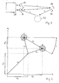
- the reader 10 comprises a transmitter which emits a carrier signal via a transmitting antenna 14 and a receiver with a receiving antenna 16, a demodulator and a receiver Evaluation.
- the detector wafer 12 comprises a detector wafer antenna 18, a control circuit, a memory and a modulator.
- the detector wafer 12 may be a passive, powered by the reader 10 detection wafer or a detection wafer with its own power source.
- the modulator of the detector plate 12 modulates the carrier signal of the reading device 10 by damping in time its modulation content. This represents a useful signal component which passes as a detection signal with the transit time ⁇ t from the detector wafer antenna 18 to the receiving antenna 16 of the reading device 10.
- the receiving antenna 16 of the reader 10 and components of the carrier signal with the duration ⁇ r itself by direct coupling of the transmitting antenna 14 and by reflections of the carrier signal with the transit time ⁇ d2 to objects 20. Although also reflections of the detection signal with the transit time ⁇ d1 occur on objects 20, but these are not considered further below.
- Fig. 2 shows a pointer image of the signal components at the receiving antenna of the reading device.
- the components of the carrier signal are combined as direct coupling to the receiving antenna and the components formed by reflections of the carrier signal to objects components U K , which consist in the complex pointer image of an in-phase component U KI and a quadrature component U KQ . These components are not modulated by the detector wafer.
- the carrier signal is modulated with a modulation signal which changes in the embodiment between two modulation states A and B and is represented by a pointer U A for the modulation state A and a pointer U B for the modulation state B.
- the modulated component formed by the detection signal is as a component U T , consisting in the complex pointer image of an in-phase component U TI and a quadrature component U TQ . Disturbance components of the transmission path influence the position of the modulation states A and B in the complex pointer image, which is represented by circular regions with several scattering values.
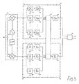
- the evaluation circuit comprises a first I / Q demodulator 22, comprising a first multiplier 24, a second multiplier 26 and a local oscillator 28.
- the first multiplier 24 and the second multiplier 26 receive on the one hand an input signal U RF and on the other hand an oscillator signal of the local oscillator 28 with the same frequency as the carrier frequency of the input signal U RF .
- the oscillator signal is supplied to the first multiplier 24 as U LO * cos ( ⁇ t) and the second multiplier 26 phase shifted by 90 ° as U LO * sin ( ⁇ t).
- the signal path is divided into an in-phase channel I and a quadrature-phase channel Q.
- a signal processor 30 for the in-phase channel I and a signal processor 32 for the quadrature phase channel Q This is followed by a signal processor 30 for the in-phase channel I and a signal processor 32 for the quadrature phase channel Q.
- Outputs of the signal processor 30 for the in-phase channel I and the signal processor 32 for the quadrature phase channel Q lead to a computer 34, which carries out a trigonometric calculation of the phase position and the amplitude.
- Signal processors 30 and 32 include n multipliers 36, 36 ', 36 “; 38, 38', 38” and summers 40, 40 ', 40 “; 42, 42 ', 42 “for multiplying and summing the multiplication results of the signals of the in-phase channel I and the quadrature phase channel Q with evaluation functions f 1 (t), f 2 (t), f n (t), a common amplitude evaluator 44 and one summer each 48, 50 for averaging over several evaluation periods.
- the signals U I of the in-phase channel I and the signals U Q of the quadrature phase channel Q are supplied to the respective multipliers 36, 36 ', 36 ", 38, 38', 38" and with different evaluation functions f 1 (t), f 2 (FIG. t) f n (t) is multiplied.
- the evaluation functions each comprise an expected within a measurement period signal sequence of the detector and differ z., by the phase position of the expected burst.
- the multiplication is carried out separately for each sample within the measurement period (in case of digital signal processing For example, for each bit clock.) Subsequently, the multiplication products for each sample within the evaluation period are evaluated by the summers 40, 40 ', 40 "; 42, 42 ', 42 "summed.
- the maximum values are evaluated and selected by the following common amplitude evaluator 44 as amplitude values of the signal components A bI for the in-phase channel I and A bQ for the quadrature- phase channel Q.
- the following summers 48; 50 form averages of the amplitude values of the signal components over several evaluation periods, eg. B. over a complete data telegram of Detektierplättchens. By normalization, the absolute amplitudes of the signals for the in-phase channel I and for the quadrature-phase channel Q can also be determined.
- Both the averaged amplitudes A tI of the signals for the in-phase channel I and the averaged amplitudes A tQ of the signals for the quadrature phase channel Q are supplied to the subsequent computer 34.
- the computer 34 determines therefrom the phase position ⁇ t and the resulting amplitude A t
- U A I U A / 2 * cos ( ⁇ A ) + U K I / 2
- U B I U B / 2 * cos ( ⁇ B ) + U K I / 2
- U A Q U A / 2 * sin ( ⁇ A ) + U K Q / 2
- U B Q U B / 2 * sin ( ⁇ A ) + U K Q / 2 ,
Landscapes
- Engineering & Computer Science (AREA)
- Radar, Positioning & Navigation (AREA)
- Remote Sensing (AREA)
- Physics & Mathematics (AREA)
- General Physics & Mathematics (AREA)
- Computer Networks & Wireless Communication (AREA)
- Radar Systems Or Details Thereof (AREA)
- Container, Conveyance, Adherence, Positioning, Of Wafer (AREA)
Applications Claiming Priority (1)
| Application Number | Priority Date | Filing Date | Title |
|---|---|---|---|
| DE102005009579A DE102005009579B4 (de) | 2005-02-28 | 2005-02-28 | Verfahren zur Lokalisierung eines Detektierplättchens |
Publications (2)
| Publication Number | Publication Date |
|---|---|
| EP1696245A2 true EP1696245A2 (fr) | 2006-08-30 |
| EP1696245A3 EP1696245A3 (fr) | 2006-09-06 |
Family
ID=36602440
Family Applications (1)
| Application Number | Title | Priority Date | Filing Date |
|---|---|---|---|
| EP05024992A Withdrawn EP1696245A3 (fr) | 2005-02-28 | 2005-11-16 | Procédé destiné à la localisation d'une plaquette de détection |
Country Status (3)
| Country | Link |
|---|---|
| US (1) | US7391360B2 (fr) |
| EP (1) | EP1696245A3 (fr) |
| DE (1) | DE102005009579B4 (fr) |
Cited By (5)
| Publication number | Priority date | Publication date | Assignee | Title |
|---|---|---|---|---|
| US7391360B2 (en) * | 2005-02-28 | 2008-06-24 | ASTRA Gesellschaft für Asset Management mbH & Co. KG | Method for locating a detection microchip |
| FR2927495A1 (fr) * | 2008-02-12 | 2009-08-14 | Yves Reza | Realisation de transactions securisees de proximite avec un dispositif tel qu'un terminal radio portable |
| WO2010080468A1 (fr) * | 2008-12-19 | 2010-07-15 | Symbol Technologies, Inc. | Détermination de mouvement d'étiquette rfid |
| WO2010091746A1 (fr) * | 2009-02-10 | 2010-08-19 | Siemens Aktiengesellschaft | Procédé et système pour déterminer la distance, la vitesse et/ou la direction de déplacement d'une étiquette rfid |
| US20230360240A1 (en) * | 2020-11-05 | 2023-11-09 | Sony Group Corporation | Information processing device, information processing method, and information processing program |
Families Citing this family (6)
| Publication number | Priority date | Publication date | Assignee | Title |
|---|---|---|---|---|
| JP5355936B2 (ja) * | 2007-06-28 | 2013-11-27 | 日本信号株式会社 | リーダライタ、及び物品仕分システム |
| US8102267B1 (en) * | 2008-02-07 | 2012-01-24 | Board Of Regents, The University Of Texas System | Single antenna single reader system and method for locating a tag |
| US8823577B2 (en) * | 2009-12-23 | 2014-09-02 | Itrack, Llc | Distance separation tracking system |
| US11030424B2 (en) | 2018-03-13 | 2021-06-08 | Denso Wave Incorporated | Apparatus for detecting tag movements and wireless tag reader |
| JP7099228B2 (ja) * | 2018-09-26 | 2022-07-12 | 株式会社デンソーウェーブ | 無線タグリーダ |
| FR3081620B1 (fr) * | 2018-05-25 | 2020-07-17 | Greenerwave | Procede de determination d'une caracteristique d'un recepteur dans un milieu, et systeme mettant en oeuvre ce procede |
Citations (3)
| Publication number | Priority date | Publication date | Assignee | Title |
|---|---|---|---|---|
| US5233353A (en) | 1991-09-18 | 1993-08-03 | France Telecom | System for measuring the distance between two stations mobile with regard to one another |
| US20030028323A1 (en) | 2001-08-02 | 2003-02-06 | Zeitler David W. | Material handling systems with high frequency radio location devices |
| WO2004059340A1 (fr) | 2002-12-20 | 2004-07-15 | Siemens Aktiengesellschaft | Procede servant a determiner la distance entre une station de base et un objet mobile, et station de base et systeme d'identification conçus pour ce procede |
Family Cites Families (20)
| Publication number | Priority date | Publication date | Assignee | Title |
|---|---|---|---|---|
| US4229737A (en) * | 1978-02-06 | 1980-10-21 | Cubic Western Data | Ranging system and method for determining the range of a vehicle from a plurality of reference points |
| US5553407A (en) * | 1995-06-19 | 1996-09-10 | Vermeer Manufacturing Company | Excavator data acquisition and control system and method of use |
| GB2310099B (en) * | 1996-02-08 | 2000-08-02 | Mecon Limited | Radar for vibration detection |
| US6111536A (en) * | 1998-05-26 | 2000-08-29 | Time Domain Corporation | System and method for distance measurement by inphase and quadrature signals in a radio system |
| AU6217100A (en) * | 1999-07-15 | 2001-02-05 | Pinpoint Corporation | Method and apparatus for mobile tag reading |
| DE19946161A1 (de) * | 1999-09-27 | 2001-04-26 | Siemens Ag | Verfahren zur Abstandsmessung |
| US7580378B2 (en) * | 2000-06-06 | 2009-08-25 | Alien Technology Corporation | Distance/ranging determination using relative phase data |
| DE10241463A1 (de) * | 2002-09-06 | 2004-03-18 | Robert Bosch Gmbh | Radarmessvorrichtung, insbesondere für ein Kraftfahrzeug, und Verfahren zum Betreiben einer Radarmessvorrichtung |
| US7119738B2 (en) * | 2004-03-01 | 2006-10-10 | Symbol Technologies, Inc. | Object location system and method using RFID |
| US7030761B2 (en) * | 2004-03-16 | 2006-04-18 | Symbol Technologies | Multi-resolution object location system and method |
| US20070023520A1 (en) * | 2004-04-22 | 2007-02-01 | Matsushita Electric Industrial Co., Ltd. | Contactless reader/writer |
| US7170412B2 (en) * | 2004-08-31 | 2007-01-30 | Symbol Technologies, Inc. | Angle of position object location system and method |
| US7574732B2 (en) * | 2004-09-29 | 2009-08-11 | Symbol Technologies Inc | Object location based security using RFID |
| US8253539B2 (en) * | 2004-11-30 | 2012-08-28 | Symbol Technologies, Inc. | Rfid reader management system and method |
| US7242293B2 (en) * | 2004-12-21 | 2007-07-10 | Intel Corporation | Radio-frequency identification apparatus, systems, and methods |
| DE102005009579B4 (de) * | 2005-02-28 | 2010-04-22 | ASTRA Gesellschaft für Asset Management mbH & Co. KG | Verfahren zur Lokalisierung eines Detektierplättchens |
| JP4806954B2 (ja) * | 2005-04-15 | 2011-11-02 | オムロン株式会社 | 情報処理装置、情報処理装置の制御方法、情報処理装置の制御プログラム、および情報処理装置の制御プログラムを記録した記録媒体 |
| US20060284727A1 (en) * | 2005-06-16 | 2006-12-21 | Psc Scanning, Inc. | Method and system with functionality for finding range between an electronic tag reader and tag |
| US7405662B2 (en) * | 2005-06-14 | 2008-07-29 | Datalogic Mobile, Inc. | Wireless tag ranging |
| US20070096876A1 (en) * | 2005-10-20 | 2007-05-03 | Raj Bridgelall | Adaptive RFID devices |
-
2005
- 2005-02-28 DE DE102005009579A patent/DE102005009579B4/de not_active Expired - Fee Related
- 2005-11-16 EP EP05024992A patent/EP1696245A3/fr not_active Withdrawn
-
2006
- 2006-02-28 US US11/364,656 patent/US7391360B2/en not_active Expired - Fee Related
Patent Citations (3)
| Publication number | Priority date | Publication date | Assignee | Title |
|---|---|---|---|---|
| US5233353A (en) | 1991-09-18 | 1993-08-03 | France Telecom | System for measuring the distance between two stations mobile with regard to one another |
| US20030028323A1 (en) | 2001-08-02 | 2003-02-06 | Zeitler David W. | Material handling systems with high frequency radio location devices |
| WO2004059340A1 (fr) | 2002-12-20 | 2004-07-15 | Siemens Aktiengesellschaft | Procede servant a determiner la distance entre une station de base et un objet mobile, et station de base et systeme d'identification conçus pour ce procede |
Cited By (5)
| Publication number | Priority date | Publication date | Assignee | Title |
|---|---|---|---|---|
| US7391360B2 (en) * | 2005-02-28 | 2008-06-24 | ASTRA Gesellschaft für Asset Management mbH & Co. KG | Method for locating a detection microchip |
| FR2927495A1 (fr) * | 2008-02-12 | 2009-08-14 | Yves Reza | Realisation de transactions securisees de proximite avec un dispositif tel qu'un terminal radio portable |
| WO2010080468A1 (fr) * | 2008-12-19 | 2010-07-15 | Symbol Technologies, Inc. | Détermination de mouvement d'étiquette rfid |
| WO2010091746A1 (fr) * | 2009-02-10 | 2010-08-19 | Siemens Aktiengesellschaft | Procédé et système pour déterminer la distance, la vitesse et/ou la direction de déplacement d'une étiquette rfid |
| US20230360240A1 (en) * | 2020-11-05 | 2023-11-09 | Sony Group Corporation | Information processing device, information processing method, and information processing program |
Also Published As
| Publication number | Publication date |
|---|---|
| DE102005009579B4 (de) | 2010-04-22 |
| US20060220861A1 (en) | 2006-10-05 |
| DE102005009579A1 (de) | 2006-09-07 |
| US7391360B2 (en) | 2008-06-24 |
| EP1696245A3 (fr) | 2006-09-06 |
Similar Documents
| Publication | Publication Date | Title |
|---|---|---|
| DE4407369C2 (de) | Verfahren und Schaltungsanordnung zur Laufzeitmessung sowie deren Verwendung | |
| DE2410500C3 (de) | Pulsradarsystem linear zeitverknüpfter Tragerfrequenz mit hohem Entfernungsauflösungsvermögen | |
| DE2652665C2 (de) | Radargerät, von dem pseudostatistisch kodierte Signale abgestrahlt werden | |
| DE4244608C2 (de) | Mittels eines Computers durchgeführtes Radarverfahren zur Messung von Abständen und Relativgeschwindigkeiten zwischen einem Fahrzeug und vor ihm befindlichen Hindernissen | |
| EP2845026B1 (fr) | Procédé et ensemble pour la détection relative de position de stations par radiolocalisation | |
| DE102019124851A1 (de) | System und verfahren zum bestimmen von störungen bei einem radarsystem | |
| DE102018132745A1 (de) | Fmcw radar mit störsignalunterdrückung im zeitbereich | |
| DE102006004023A1 (de) | Vorrichtung und Verfahren zur mehrdimensionalen Ortung von Zielobjekten, insbesondere RFID-Transpondern | |
| EP3660532B1 (fr) | Procédé, dispositif et agencement de détermination de l'angle d'incidence (aoa) permettant de localiser des objets | |
| DE102007054298B4 (de) | Radarvorrichtung | |
| DE102020115709B3 (de) | Automobilradaranordnung und verfahren zur objektdetektion durch ein fahrzeugradar | |
| WO2004059340A1 (fr) | Procede servant a determiner la distance entre une station de base et un objet mobile, et station de base et systeme d'identification conçus pour ce procede | |
| EP1216424A1 (fr) | Procede de mesure de distance | |
| EP1696245A2 (fr) | Procédé destiné à la localisation d'une plaquette de détection | |
| DE2348458A1 (de) | Impulsradarsystem | |
| DE112012001279T5 (de) | Fahrzeugneigungs-Detektiervorrichtung | |
| DE3030515A1 (de) | Radargeraet zum erkennen und zum orten von fahrzeugen | |
| EP1825293B1 (fr) | Procede electronique de mesure | |
| DE69304373T2 (de) | Verfahren und Vorrichtung zur Erkennung von durch ein Sekundärradar mittels Phasenanalyse empfangenen vermischten Impulsen | |
| EP3467451A1 (fr) | Procédé et appareil de mesure de niveau de remplissage permettant de déterminer le niveau de remplissage d'un milieu au moyen d'une mesure radar continue | |
| DE69508378T2 (de) | Mehrkanalradar | |
| DE102016119484B4 (de) | Positionsermittlungseinrichtung | |
| DE3116390C2 (de) | Signalverarbeitungsschaltung für Puls-Doppler-Radarsysteme | |
| DE102019201742A1 (de) | Transceiver und Verfahren zur Distanzmessung | |
| DE102022116281A1 (de) | Radarvorrichtung und verfahren |
Legal Events
| Date | Code | Title | Description |
|---|---|---|---|
| PUAI | Public reference made under article 153(3) epc to a published international application that has entered the european phase |
Free format text: ORIGINAL CODE: 0009012 |
|
| PUAL | Search report despatched |
Free format text: ORIGINAL CODE: 0009013 |
|
| AK | Designated contracting states |
Kind code of ref document: A2 Designated state(s): AT BE BG CH CY CZ DE DK EE ES FI FR GB GR HU IE IS IT LI LT LU LV MC NL PL PT RO SE SI SK TR |
|
| AX | Request for extension of the european patent |
Extension state: AL BA HR MK YU |
|
| AK | Designated contracting states |
Kind code of ref document: A3 Designated state(s): AT BE BG CH CY CZ DE DK EE ES FI FR GB GR HU IE IS IT LI LT LU LV MC NL PL PT RO SE SI SK TR |
|
| AX | Request for extension of the european patent |
Extension state: AL BA HR MK YU |
|
| 17P | Request for examination filed |
Effective date: 20070301 |
|
| 17Q | First examination report despatched |
Effective date: 20070329 |
|
| AKX | Designation fees paid |
Designated state(s): DE FR GB |
|
| APBK | Appeal reference recorded |
Free format text: ORIGINAL CODE: EPIDOSNREFNE |
|
| APBN | Date of receipt of notice of appeal recorded |
Free format text: ORIGINAL CODE: EPIDOSNNOA2E |
|
| APBR | Date of receipt of statement of grounds of appeal recorded |
Free format text: ORIGINAL CODE: EPIDOSNNOA3E |
|
| APAF | Appeal reference modified |
Free format text: ORIGINAL CODE: EPIDOSCREFNE |
|
| APBT | Appeal procedure closed |
Free format text: ORIGINAL CODE: EPIDOSNNOA9E |
|
| STAA | Information on the status of an ep patent application or granted ep patent |
Free format text: STATUS: THE APPLICATION HAS BEEN WITHDRAWN |
|
| 18W | Application withdrawn |
Effective date: 20131105 |