EP1698366A1 - Sterile Spritze - Google Patents
Sterile Spritze Download PDFInfo
- Publication number
- EP1698366A1 EP1698366A1 EP06101325A EP06101325A EP1698366A1 EP 1698366 A1 EP1698366 A1 EP 1698366A1 EP 06101325 A EP06101325 A EP 06101325A EP 06101325 A EP06101325 A EP 06101325A EP 1698366 A1 EP1698366 A1 EP 1698366A1
- Authority
- EP
- European Patent Office
- Prior art keywords
- cylinder
- syringe
- sealing means
- operating means
- piston
- Prior art date
- Legal status (The legal status is an assumption and is not a legal conclusion. Google has not performed a legal analysis and makes no representation as to the accuracy of the status listed.)
- Granted
Links
Images



Classifications
-
- A—HUMAN NECESSITIES
- A61—MEDICAL OR VETERINARY SCIENCE; HYGIENE
- A61M—DEVICES FOR INTRODUCING MEDIA INTO, OR ONTO, THE BODY; DEVICES FOR TRANSDUCING BODY MEDIA OR FOR TAKING MEDIA FROM THE BODY; DEVICES FOR PRODUCING OR ENDING SLEEP OR STUPOR
- A61M5/00—Devices for bringing media into the body in a subcutaneous, intra-vascular or intramuscular way; Accessories therefor, e.g. filling or cleaning devices, arm rests
- A61M5/178—Syringes
- A61M5/31—Details
- A61M5/3129—Syringe barrels
- A61M5/3135—Syringe barrels characterised by constructional features of the proximal end
-
- A—HUMAN NECESSITIES
- A61—MEDICAL OR VETERINARY SCIENCE; HYGIENE
- A61M—DEVICES FOR INTRODUCING MEDIA INTO, OR ONTO, THE BODY; DEVICES FOR TRANSDUCING BODY MEDIA OR FOR TAKING MEDIA FROM THE BODY; DEVICES FOR PRODUCING OR ENDING SLEEP OR STUPOR
- A61M5/00—Devices for bringing media into the body in a subcutaneous, intra-vascular or intramuscular way; Accessories therefor, e.g. filling or cleaning devices, arm rests
- A61M5/178—Syringes
- A61M5/31—Details
- A61M2005/3117—Means preventing contamination of the medicament compartment of a syringe
- A61M2005/3121—Means preventing contamination of the medicament compartment of a syringe via the proximal end of a syringe, i.e. syringe end opposite to needle cannula mounting end
-
- A—HUMAN NECESSITIES
- A61—MEDICAL OR VETERINARY SCIENCE; HYGIENE
- A61M—DEVICES FOR INTRODUCING MEDIA INTO, OR ONTO, THE BODY; DEVICES FOR TRANSDUCING BODY MEDIA OR FOR TAKING MEDIA FROM THE BODY; DEVICES FOR PRODUCING OR ENDING SLEEP OR STUPOR
- A61M5/00—Devices for bringing media into the body in a subcutaneous, intra-vascular or intramuscular way; Accessories therefor, e.g. filling or cleaning devices, arm rests
- A61M5/178—Syringes
- A61M5/31—Details
- A61M5/315—Pistons; Piston-rods; Guiding, blocking or restricting the movement of the rod or piston; Appliances on the rod for facilitating dosing ; Dosing mechanisms
Definitions
- the present invention relates generally to a syringe for fluid, preferably a liquid medium, with a cylinder, a piston portion which is arranged in the cylinder and slidable on its inside, and an operating means connected to the piston portion for sliding thereof.
- the operating means projects from a first end of the cylinder and the cylinder has at a second end an inlet and outlet part for the fluid.
- the present invention relates to a syringe for taking up and discharging a fluid, said syringe having on the one hand a cylinder for taking up, for instance, a liquid medium, the cylinder having a first end with an opening and a second end with an inlet and outlet part, and, on the other hand, a sealingly guided piston portion which is movable back and forth inside the cylinder between its first and second ends, said piston portion being actuated by the operating means which projects from the opening at the first end of the cylinder to be, in turn, actuatable from the outside for moving the piston portion back and forth in the cylinder.
- a syringe of the above type can be used in a variety of fields, for instance as sampling or injection syringe in the medical field.
- An application which in this case is particularly preferred but not limiting is, for instance, in the pharmaceutical and biotechnology field and to some extent also in fields such as foods and cosmetics.
- these fields there is a need for routine sampling and analysis of different media, for instance for microbiological control, cell counting or, where appropriate, chemical analyses, or supply of regulating or active media in certain process steps in manufacture of products in the fields in question.
- manufacture In such manufacture involving stringent requirements as to no contamination, or minor contamination, of the media included in the process, manufacture normally takes place in a closed process vessel. There is, however, a risk of contamination when one or more media are to be supplied to the process vessel or a sample is to be taken from the process vessel. Due to this risk of contamination in and around the process vessel, the supply and sampling of the media therefore take place in clean room environment, which requires great investments, expensive equipment and acceptable working conditions for the staff.
- the syringe according to the present invention is in the first place, but not exclusively, intended to be used in contamination-free take-up from a process vessel to a collecting vessel or the like.
- the syringe can be used to transfer fluid from a collecting vessel and supply the fluid to a process vessel or vice versa.
- the syringe can also be arranged for other dosing, transport or sampling, such as transfer of the fluid to a laboratory for analysis etc.
- the piston portion When the piston portion then, by the operating means, which can be a piston rod, is again moved inwards in the cylinder from the turning position to the starting position to discharge the medium to be added, analysed etc, the contaminants accompany the medium out of the syringe. This can wholly or partly destroy or damage the medium and make it difficult, or impossible, for the medium to be used, analysed etc. Owing to the contamination, the medium can alternately, or in addition, be dangerous to use.
- the operating means which can be a piston rod
- this film can additionally increase the risk that contaminants get stuck on the inside of the cylinder, and in the cases where the syringe is used several times before being finally discarded or cleaned for reuse, the risk also increases that the medium in the syringe should be contaminated by contaminants or microorganisms more easily getting stuck on the film formed.
- An object of the present invention is to provide a syringe of the type stated by way of introduction, which eliminates one of the above drawbacks and risks in a simple and effective manner.
- Another object of the invention is to provide such a syringe, which thus is contamination-sealed in the sense that exterior microorganisms or other contaminants cannot mix with the medium received in the syringe and contaminate this.
- Yet another object of the invention is to provide such a syringe in which current requirements as to contamination-free transfer of the medium involved all the way from the process vessel to adding and/or analysing etc. through the syringe are satisfied.
- a further object of the invention is to provide a syringe which is inexpensive and simple to manufacture.
- a syringe for fluid comprising a cylinder, a piston portion which is arranged in the cylinder and slidable on its inside, and an operating means connected to the piston portion for sliding thereof.
- the operating means projects from a first end of the cylinder and the cylinder has at a second end an inlet and outlet part for said fluid.
- a sealing means is connected in a contamination-free manner to the cylinder in the area of its first end and extends into the cylinder to isolate, sealed against contamination, the inside of the cylinder from the environment.
- the sealing means is at least connected in a contamination-free manner to the cylinder and extends into the cylinder to isolate, sealed against contamination, the inside of the cylinder from the operating means which can be, for instance, a piston rod.
- the syringe is preferably intended for sampling of liquids, but of course the present invention can be used in other applications and also for other media, such as gases.
- the sealing means protects the inside of the cylinder from the environment and the risk of contamination. This is ensured by the sealing means separating the piston rod from the inside of the cylinder, thus forming a chamber isolated from the environment and defined by the cylinder, the sealing means and a piston portion at the inner end of the piston rod. This isolated chamber is presterilised simultaneously with the syringe, after which the chamber remains free of contaminants from the environment outside the syringe.
- sealing means is arranged to seal between the inside of the cylinder and an inner end of the operating means extending into the cylinder. This is ensured by the sealing means extending from sealed connection to the edge of the first end of the cylinder to sealed connection to the inner end of the operating means.
- This sealing effect can be provided at the inner end of the operating means in various ways, for instance by the end being circumferentially isolated from the cylinder by the sealing means.
- said sealing means is located substantially inside the cylinder.
- the entire sealing means is positioned inside the cylinder except for the part of the inner end of the sealing means which is attached to the second end of the cylinder.
- the sealing means can be designed to accompany, partially folded in two, the operating means out of the opening of the cylinder.
- the sealing means preferably has an open end into which the inner end of the operating means extends. It is also conceivable for the inner end of the sealing means to be provided with an opening, which requires a piston portion or the like to seal between the inner end of the operating means and the inside of the cylinder.
- the open end of the sealing means is connected to the first end of the cylinder.
- This can be ensured in various ways, for instance by the elastic sealing means being "turned inside out” around the edge of the second end of the cylinder, or alternatively the sealing means being locked in a form-fitting manner by means of a sleeve at the second end of the cylinder.
- a guide sleeve is arranged at the first end of the cylinder to guide the operating means.
- This guide sleeve cooperates with the operating means.
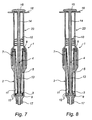
- Cooperation between the guide sleeve and the operating means is achieved either by flanges of the piston rod which extend radially out from the piston rod to abut against the guide sleeve as shown in Figs 1-5 and 7, or by the guide sleeve having a portion extending inwards to the operating means as shown in Fig. 6.
- the sealing means forms, at its end opposite to the open end, a piston-like portion, which is movable by the operating means inside the cylinder, said piston-like portion sealingly engaging the inside of the cylinder, a corresponding embodiment being shown in Fig. 7.
- the sealing means is formed like a bellows so that the bellows folds during said movement of the operating means as shown in Fig. 5; in another alternative the sealing means is flat and accompanies, folded in two, the operating means out of the first end of the cylinder during said movement of the operating means.
- the open end of the sealing means is connected to the first end of the cylinder by being turned inside out around the edge of the first end of the cylinder.
- the sealing means is made of an elastic and sealing material in order to exclude contaminants from the fluid that is being handled by the syringe.
- the syringe and the sealing means are presterilised, preferably by irradiation, autoclaving or some other appropriate method, whereby the syringe is kept sterile, above all on the inside, up to the occasion of use.
- the second end of the sealing means is movable and the inner end of the sealing means is held still at the first end of the cylinder. In this way, a deformation of the sealing means is provided while at the same time fluid is sucked into the chamber of the syringe.
- the syringe generally designated 1 in the drawing is, as mentioned above, in the first place intended to be used in contamination-free take-up from process vessels, collecting vessels or the like in order to transfer a medium to another process vessel or the like, transfer of the medium to a laboratory for analysis etc.
- syringe according to the invention there is nothing to prevent the syringe according to the invention from being used in other applications, for instance as a conventional sampling or injection syringe in the medical field, such as in medical care.
- Other conceivable applications are as dosing syringe for controlled dosing of components included in a composition or pharmaceutical preparation, as laboratory syringe etc.
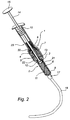
- the main components of the syringe 1 are a cylinder 2, a piston portion 3, a piston rod 4 and a sealing means 5.
- the cylinder 2 is formed as a hollow, substantially straight circular cylinder to take up a liquid medium 6, or a gas, from a collecting vessel or the like (not shown).
- the cylinder 2 has a first end 7 with a circular opening 8 and a second end 9 with an inlet and outlet part suitably integrated with the cylinder.
- the piston portion 3 is also circular and is guided in the cylinder 2 in such a manner that it is movable back and forth in the cylinder between the first and second ends 7, 9 thereof.
- the piston portion 3 is sealingly guided in the cylinder 2 by sealingly engaging the inside 11 of the cylinder with a seal which, in the embodiment according to Fig. 1, is integrated in the sealing means 5 and has the shape of one or more sealing edges 12 or ridges.
- the sealing edges 12 are preferably made of the same material as the sealing means 5, which can be a suitable elastomer, such as rubber or silicone, or alternatively some other polymer material.
- the piston rod 4 is circular in cross-section and is at its inner end 13 connected to the sealing means 5 which forms a piston portion 3.
- the piston rod can also be X-shaped in cross-section or have some other cross-section.
- the piston rod 4 projects from the opening 8 at the first end of the cylinder and has at its outer end 14 a handle 15 which here has the shape of a round disc and suitably is integrated with the piston rod 4.
- a sleeve 23 is fastened around the first end of the cylinder 2 and secures the sealing means at the first end of the cylinder 2.
- the sleeve 23 also guides the flanges 10 of the piston rod to perform a control movement of the piston rod and the piston portion inside the cylinder 2.
- the end of the sleeve is formed on its outside with a counter-handle 16 which is suitably integrated with the sleeve.
- the piston rod 4 is manually actuatable from the outside by the handle 15 and the counter-handle 16 to move the piston portion 3 back and forth in the cylinder 2.
- the inlet and outlet part 17 can be designed in various ways; in this case like a connecting nozzle to be connected to a tube 18 from the connecting vessel or the like (not shown).
- the inlet and outlet part 17 could be designed as a holder or connection for an injection needle or the like.
- the sealing means 5 is made of an elastic and substantially diffusion-tight material, such as rubber or a suitable plastic, and is flat, or alternatively formed as a bellows, to be able to adjust to the movements of the syringe in a manner that will be described below.
- the sealing means 5 is connected to the cylinder 2 by gluing, fusion welding, pressing or some other suitable sealing, to enclose, sealed against contamination or free of contamination, the opening 8 in the first end 7 of the cylinder and also isolate the piston rod 4 extending into the cylinder 2 from the inside 11 of the cylinder in order to prevent contamination of the inside of the cylinder and eliminate the risk that the medium 6 handled in the syringe should be contaminated.
- the sealing means 5 has an upper open end 20, which is sealed and connected, sealed against contamination, to the cylinder 2 in the area of its first end 7, more specifically to the outside 21 of the cylinder, as shown at 25.
- the sealing means 5 is in the current embodiment closed and forms a piston portion which has one or more cylindrical sealing edges which sealingly engage the inside of the cylinder.
- the end 22, opposite to the open end 20, of the sealing means 5 is open and then, suitably in a sealed manner connected directly to the piston rod 4, which is arranged with a, detachable or integrated, piston 3 for sealing against the inside 11 of the cylinder.
- the piston can preferably be formed so that, when it is attached to the piston rod 4, also the sealing means 5 is connected, sealed against contamination, to the cylinder 2 and/or the piston 3, which can take place by clamping, barbs, form-fit locking, adhesive or in some other suitable manner.
- the cylinder 2 is suitably made of a transparent material, for instance an appropriate plastic, and presterilised by a conventional method, such as irradiation or autoclaving.
- the sleeve 23 has a part connecting to the outside of the first end 7 of the cylinder 2 and a part extending into the first end of the cylinder.
- the sleeve 23 is adapted to secure the open end 20 of the sealing means to the opening 8 of the cylinder in a tight-fitting manner, for instance by clamping, barbs, form-fit locking, adhesive or in some other suitable manner.
- That part of the sleeve 23 which extends into the cylinder 2 can also be used to hold the sealing means 5, apart from the fact that it can be designed as a guide for the piston rod when moving up and down in the cylinder.
- the total length of the syringe 1 will be shorter than in the embodiment according to, for instance, Figs 1-4.
- the sealing means 5 can be formed as a smooth and flexible cylinder or cone, which is open at an upper end 20 and has a sealing piston portion 3, alternatively open, also at the opposite end. That part of the sealing means 5 which interconnects these two ends can be designed in various ways, in order to, for instance, allow good movability of the piston rod 4 of the syringe, for instance as a bellows or in some other suitable shape.
- the sealing means 5 is pressed against the piston rod 4 and, as shown in Fig. 3, the sealing means 5 can be provided to accompany, folded in two, the piston rod 4 out of the opening 8 of the cylinder 2.
Landscapes
- Health & Medical Sciences (AREA)
- Animal Behavior & Ethology (AREA)
- Veterinary Medicine (AREA)
- Anesthesiology (AREA)
- Biomedical Technology (AREA)
- Heart & Thoracic Surgery (AREA)
- Hematology (AREA)
- Engineering & Computer Science (AREA)
- General Health & Medical Sciences (AREA)
- Life Sciences & Earth Sciences (AREA)
- Public Health (AREA)
- Vascular Medicine (AREA)
- Infusion, Injection, And Reservoir Apparatuses (AREA)
- Sampling And Sample Adjustment (AREA)
- Apparatus For Disinfection Or Sterilisation (AREA)
- Medicines Containing Material From Animals Or Micro-Organisms (AREA)
Applications Claiming Priority (1)
| Application Number | Priority Date | Filing Date | Title |
|---|---|---|---|
| SE0500507A SE529693C2 (sv) | 2005-03-04 | 2005-03-04 | Steril spruta |
Publications (2)
| Publication Number | Publication Date |
|---|---|
| EP1698366A1 true EP1698366A1 (de) | 2006-09-06 |
| EP1698366B1 EP1698366B1 (de) | 2009-11-18 |
Family
ID=36570458
Family Applications (1)
| Application Number | Title | Priority Date | Filing Date |
|---|---|---|---|
| EP06101325A Expired - Lifetime EP1698366B1 (de) | 2005-03-04 | 2006-02-06 | Sterile Spritze |
Country Status (8)
| Country | Link |
|---|---|
| US (1) | US7597683B2 (de) |
| EP (1) | EP1698366B1 (de) |
| JP (1) | JP4495092B2 (de) |
| CN (1) | CN100593423C (de) |
| AT (1) | ATE448818T1 (de) |
| DE (1) | DE602006010458D1 (de) |
| ES (1) | ES2336134T3 (de) |
| SE (1) | SE529693C2 (de) |
Cited By (2)
| Publication number | Priority date | Publication date | Assignee | Title |
|---|---|---|---|---|
| US7998106B2 (en) | 2004-05-03 | 2011-08-16 | Thorne Jr Gale H | Safety dispensing system for hazardous substances |
| FR3023172A1 (fr) * | 2014-07-07 | 2016-01-08 | Jls Production | Seringue comprenant une membrane et une bague de fixation de ladite membrane |
Families Citing this family (32)
| Publication number | Priority date | Publication date | Assignee | Title |
|---|---|---|---|---|
| EP2292297B1 (de) | 2002-04-26 | 2020-06-03 | EMD Millipore Corporation | Dampfsterilisierbares medizinisches Ventil zur einmaligen Verwendung |
| US10610406B2 (en) * | 2004-07-21 | 2020-04-07 | Vanderbilt University | Drug delivery device and applications of same |
| US7293477B2 (en) | 2003-12-23 | 2007-11-13 | Millipore Corporation | Disposable, pre-sterilized fluid receptacle sampling device |
| JP4591409B2 (ja) * | 2006-06-01 | 2010-12-01 | 株式会社島津製作所 | 分注チップ及びそれを用いた反応キット |
| US8405508B2 (en) | 2006-08-09 | 2013-03-26 | Emd Millipore Corporation | Use of gamma hardened RFID tags in pharmaceutical devices |
| US8957778B2 (en) | 2007-08-02 | 2015-02-17 | Emd Millipore Corporation | Sampling system |
| SG153002A1 (en) | 2007-11-16 | 2009-06-29 | Millipore Corp | Fluid transfer device |
| DE102008062405A1 (de) * | 2008-12-17 | 2010-11-18 | Lts Lohmann Therapie-Systeme Ag | Injektor mit Zylinder-Kolben-Einheit und dauerhaft sterilem aktiven Kolbenhemd |
| FR2940440B1 (fr) | 2008-12-18 | 2010-12-24 | Millipore Corp | Dispositif pour le transfert d'un milieu |
| FR2940439B1 (fr) | 2008-12-18 | 2011-02-11 | Millipore Corp | Dispositif pour le transfert d'un milieu |
| JP5268628B2 (ja) * | 2008-12-26 | 2013-08-21 | 川崎重工業株式会社 | ピペッタ用隔壁ユニット及びピペット |
| US8544497B2 (en) | 2009-10-30 | 2013-10-01 | Emd Millipore Corporation | Fluid transfer device and system |
| US8511517B2 (en) * | 2009-11-05 | 2013-08-20 | Fishman Corporation | Protective syringe sleeve |
| WO2012061140A1 (en) | 2010-10-25 | 2012-05-10 | Medrad, Inc. | Bladder syringe fluid delivery system |
| US9498570B2 (en) | 2010-10-25 | 2016-11-22 | Bayer Healthcare Llc | Bladder syringe fluid delivery system |
| US9180252B2 (en) | 2012-04-20 | 2015-11-10 | Bayer Medical Care Inc. | Bellows syringe fluid delivery system |
| KR102158399B1 (ko) * | 2012-08-31 | 2020-09-21 | 유니바사루 바이오 리사치 가부시키가이샤 | 변형요소내장 분주팁, 변형요소내장 분주장치 및 변형요소내장 분주처리방법 |
| US9814871B2 (en) | 2013-03-15 | 2017-11-14 | Bayer Healthcare Llc | Connector assembly for syringe system |
| JP6391811B2 (ja) * | 2015-03-27 | 2018-09-19 | 株式会社日立ハイテクノロジーズ | 電気泳動装置および電気泳動方法 |
| WO2017091635A1 (en) | 2015-11-25 | 2017-06-01 | Bayer Healthcare Llc | Syringe and connector system |
| JP6914913B2 (ja) * | 2016-03-29 | 2021-08-04 | テルモ株式会社 | 薬液投与器具、薬液投与器具の使用方法及び薬液投与器具の製造方法 |
| GB2576694B (en) * | 2018-06-14 | 2022-09-07 | Janssen Pharmaceuticals Inc | Pharmaceutical product preparation device and method |
| CN115151298B (zh) | 2020-02-21 | 2026-02-24 | 拜耳医药保健有限责任公司 | 用于医疗流体递送的流体路径连接器 |
| SI4110452T1 (sl) | 2020-02-28 | 2025-03-31 | Bayer Healthcare Llc | Komplet za mešanje tekočin |
| KR102165136B1 (ko) * | 2020-03-06 | 2020-10-13 | 바즈바이오메딕(주) | 무바늘 주사기 |
| EP4121141B1 (de) | 2020-03-16 | 2026-01-28 | Bayer HealthCare LLC | Absperrhahn für flüssigkeitswege eines angiografie-injektors |
| CR20220640A (es) | 2020-06-18 | 2023-02-03 | Bayer Healthcare Llc | Aparato de suspensión de burbujas de aire en línea para trayectorias de fluidos de inyectores de angiografía |
| AU2021326454B2 (en) | 2020-08-11 | 2026-06-18 | Bayer Healthcare Llc | Features for angiography syringe |
| PH12023551507A1 (en) | 2020-12-01 | 2024-05-13 | Bayer Healthcare Llc | Cassette for retention of fluid path components for fluid injector system |
| EP4355382A1 (de) | 2021-06-17 | 2024-04-24 | Bayer Healthcare LLC | System und verfahren zur erkennung des fluidtyps in rohren für eine fluidinjektorvorrichtung |
| USD1015532S1 (en) | 2021-11-15 | 2024-02-20 | PherDal | Fertility syringe |
| US11529172B1 (en) | 2021-11-15 | 2022-12-20 | PherDal | Fertility kits with syringes and collection jars, and method of use |
Citations (4)
| Publication number | Priority date | Publication date | Assignee | Title |
|---|---|---|---|---|
| US5324266A (en) * | 1992-12-23 | 1994-06-28 | Abbott Laboratories | In-line sampling system incorporating an improved blood sampling device |
| WO1997044076A1 (es) * | 1996-05-23 | 1997-11-27 | Fernando Melero Redrado | Jeringuilla de un solo uso |
| US20010018575A1 (en) * | 1999-10-19 | 2001-08-30 | Lyza Henry Walter | Injector syringe |
| US20030187388A1 (en) * | 2002-03-28 | 2003-10-02 | Igal Sharon | Multi-compartment syringe |
Family Cites Families (14)
| Publication number | Priority date | Publication date | Assignee | Title |
|---|---|---|---|---|
| US3885710A (en) * | 1973-03-20 | 1975-05-27 | Cohen Milton | Mixing dispenser with a selectively retractable seal to permit intermixing of the ingredients |
| FR2227020B1 (de) * | 1973-04-27 | 1975-08-22 | Radiologie Cie Gle | |
| US4312344A (en) * | 1980-04-03 | 1982-01-26 | Kenova Ab | Syringe |
| US4511534A (en) | 1982-05-26 | 1985-04-16 | John T. Bennett | Liquid transfer device |
| US4713060A (en) * | 1986-06-20 | 1987-12-15 | Becton, Dickinson And Company | Syringe assembly |
| JPH0445856A (ja) * | 1990-06-14 | 1992-02-14 | Toshimasa Akiyama | ピペットチップに着ける薄膜構造 |
| US5607400A (en) | 1995-05-19 | 1997-03-04 | Becton, Dickinson And Company | Pre-fillable syringe and stopper assembly therefor |
| JPH09313606A (ja) * | 1996-05-24 | 1997-12-09 | Yoshio Morishita | 注射器 |
| FR2758088B1 (fr) * | 1997-01-06 | 1999-04-16 | Medex Sa | Dispositif d'injection de liquide medical |
| DE19925621A1 (de) | 1998-06-16 | 1999-12-23 | Buelent Yilmaz | Injektionsspritze |
| US6258062B1 (en) * | 1999-02-25 | 2001-07-10 | Joseph M. Thielen | Enclosed container power supply for a needleless injector |
| JP2000316973A (ja) * | 1999-05-12 | 2000-11-21 | Material Eng Tech Lab Inc | 薬剤入り注射器 |
| US20030065291A1 (en) * | 2001-10-01 | 2003-04-03 | Corrigan Richard F. | Syringe having flexible barrier between syringe body and plunger |
| JP2003199827A (ja) | 2001-12-28 | 2003-07-15 | Terumo Corp | シリンジ |
-
2005
- 2005-03-04 SE SE0500507A patent/SE529693C2/sv not_active IP Right Cessation
-
2006
- 2006-02-06 DE DE602006010458T patent/DE602006010458D1/de not_active Expired - Lifetime
- 2006-02-06 EP EP06101325A patent/EP1698366B1/de not_active Expired - Lifetime
- 2006-02-06 ES ES06101325T patent/ES2336134T3/es not_active Expired - Lifetime
- 2006-02-06 AT AT06101325T patent/ATE448818T1/de not_active IP Right Cessation
- 2006-02-16 JP JP2006039279A patent/JP4495092B2/ja not_active Expired - Lifetime
- 2006-02-23 US US11/359,482 patent/US7597683B2/en active Active
- 2006-03-02 CN CN200610059458A patent/CN100593423C/zh not_active Expired - Lifetime
Patent Citations (4)
| Publication number | Priority date | Publication date | Assignee | Title |
|---|---|---|---|---|
| US5324266A (en) * | 1992-12-23 | 1994-06-28 | Abbott Laboratories | In-line sampling system incorporating an improved blood sampling device |
| WO1997044076A1 (es) * | 1996-05-23 | 1997-11-27 | Fernando Melero Redrado | Jeringuilla de un solo uso |
| US20010018575A1 (en) * | 1999-10-19 | 2001-08-30 | Lyza Henry Walter | Injector syringe |
| US20030187388A1 (en) * | 2002-03-28 | 2003-10-02 | Igal Sharon | Multi-compartment syringe |
Cited By (2)
| Publication number | Priority date | Publication date | Assignee | Title |
|---|---|---|---|---|
| US7998106B2 (en) | 2004-05-03 | 2011-08-16 | Thorne Jr Gale H | Safety dispensing system for hazardous substances |
| FR3023172A1 (fr) * | 2014-07-07 | 2016-01-08 | Jls Production | Seringue comprenant une membrane et une bague de fixation de ladite membrane |
Also Published As
| Publication number | Publication date |
|---|---|
| US7597683B2 (en) | 2009-10-06 |
| JP2006242947A (ja) | 2006-09-14 |
| JP4495092B2 (ja) | 2010-06-30 |
| CN100593423C (zh) | 2010-03-10 |
| DE602006010458D1 (de) | 2009-12-31 |
| US20060211995A1 (en) | 2006-09-21 |
| SE529693C2 (sv) | 2007-10-30 |
| ATE448818T1 (de) | 2009-12-15 |
| EP1698366B1 (de) | 2009-11-18 |
| ES2336134T3 (es) | 2010-04-08 |
| CN1895689A (zh) | 2007-01-17 |
| SE0500507L (sv) | 2006-09-05 |
Similar Documents
| Publication | Publication Date | Title |
|---|---|---|
| EP1698366B1 (de) | Sterile Spritze | |
| US8505396B2 (en) | Fluid transfer device | |
| US8544349B2 (en) | Fluid transfer device | |
| JP5615176B2 (ja) | 流体移送装置 | |
| EP2313049B1 (de) | Flüssigkeitstransfervorrichtung | |
| DK2475973T3 (en) | Sampling Device. | |
| JP2002148152A (ja) | 採集容器アセンブリ | |
| US11511281B2 (en) | Fluid transfer device, system and method | |
| JPH0550293B2 (de) | ||
| CN105164016A (zh) | 受控但未分级区域用的填充装置及方法 | |
| US20080277878A1 (en) | Device and Method for Contamination-Free and/or Sterile Sealing Between At Least Two Interconnectable Connecting Means | |
| US9568113B2 (en) | Fluid transfer device | |
| EP2523644B1 (de) | Flüssigkeitstransfervorrichtung | |
| US20030097115A1 (en) | Closed sterile system devices and methods | |
| WO2025154005A1 (en) | An aseptic syringe for collection of samples |
Legal Events
| Date | Code | Title | Description |
|---|---|---|---|
| PUAI | Public reference made under article 153(3) epc to a published international application that has entered the european phase |
Free format text: ORIGINAL CODE: 0009012 |
|
| AK | Designated contracting states |
Kind code of ref document: A1 Designated state(s): AT BE BG CH CY CZ DE DK EE ES FI FR GB GR HU IE IS IT LI LT LU LV MC NL PL PT RO SE SI SK TR |
|
| AX | Request for extension of the european patent |
Extension state: AL BA HR MK YU |
|
| 17P | Request for examination filed |
Effective date: 20061115 |
|
| 17Q | First examination report despatched |
Effective date: 20061218 |
|
| RAP1 | Party data changed (applicant data changed or rights of an application transferred) |
Owner name: MILLIPORE AB |
|
| AKX | Designation fees paid |
Designated state(s): AT BE BG CH CY CZ DE DK EE ES FI FR GB GR HU IE IS IT LI LT LU LV MC NL PL PT RO SE SI SK TR |
|
| GRAP | Despatch of communication of intention to grant a patent |
Free format text: ORIGINAL CODE: EPIDOSNIGR1 |
|
| GRAS | Grant fee paid |
Free format text: ORIGINAL CODE: EPIDOSNIGR3 |
|
| GRAA | (expected) grant |
Free format text: ORIGINAL CODE: 0009210 |
|
| AK | Designated contracting states |
Kind code of ref document: B1 Designated state(s): AT BE BG CH CY CZ DE DK EE ES FI FR GB GR HU IE IS IT LI LT LU LV MC NL PL PT RO SE SI SK TR |
|
| REG | Reference to a national code |
Ref country code: GB Ref legal event code: FG4D |
|
| REG | Reference to a national code |
Ref country code: CH Ref legal event code: EP |
|
| REG | Reference to a national code |
Ref country code: IE Ref legal event code: FG4D |
|
| REF | Corresponds to: |
Ref document number: 602006010458 Country of ref document: DE Date of ref document: 20091231 Kind code of ref document: P |
|
| REG | Reference to a national code |
Ref country code: CH Ref legal event code: NV Representative=s name: OFFICE ERNEST T. FREYLINGER S.A. |
|
| REG | Reference to a national code |
Ref country code: ES Ref legal event code: FG2A Ref document number: 2336134 Country of ref document: ES Kind code of ref document: T3 |
|
| LTIE | Lt: invalidation of european patent or patent extension |
Effective date: 20091118 |
|
| PG25 | Lapsed in a contracting state [announced via postgrant information from national office to epo] |
Ref country code: LT Free format text: LAPSE BECAUSE OF FAILURE TO SUBMIT A TRANSLATION OF THE DESCRIPTION OR TO PAY THE FEE WITHIN THE PRESCRIBED TIME-LIMIT Effective date: 20091118 Ref country code: FI Free format text: LAPSE BECAUSE OF FAILURE TO SUBMIT A TRANSLATION OF THE DESCRIPTION OR TO PAY THE FEE WITHIN THE PRESCRIBED TIME-LIMIT Effective date: 20091118 Ref country code: SE Free format text: LAPSE BECAUSE OF FAILURE TO SUBMIT A TRANSLATION OF THE DESCRIPTION OR TO PAY THE FEE WITHIN THE PRESCRIBED TIME-LIMIT Effective date: 20091118 Ref country code: PT Free format text: LAPSE BECAUSE OF FAILURE TO SUBMIT A TRANSLATION OF THE DESCRIPTION OR TO PAY THE FEE WITHIN THE PRESCRIBED TIME-LIMIT Effective date: 20100318 Ref country code: IS Free format text: LAPSE BECAUSE OF FAILURE TO SUBMIT A TRANSLATION OF THE DESCRIPTION OR TO PAY THE FEE WITHIN THE PRESCRIBED TIME-LIMIT Effective date: 20100318 |
|
| PG25 | Lapsed in a contracting state [announced via postgrant information from national office to epo] |
Ref country code: LV Free format text: LAPSE BECAUSE OF FAILURE TO SUBMIT A TRANSLATION OF THE DESCRIPTION OR TO PAY THE FEE WITHIN THE PRESCRIBED TIME-LIMIT Effective date: 20091118 Ref country code: SI Free format text: LAPSE BECAUSE OF FAILURE TO SUBMIT A TRANSLATION OF THE DESCRIPTION OR TO PAY THE FEE WITHIN THE PRESCRIBED TIME-LIMIT Effective date: 20091118 Ref country code: PL Free format text: LAPSE BECAUSE OF FAILURE TO SUBMIT A TRANSLATION OF THE DESCRIPTION OR TO PAY THE FEE WITHIN THE PRESCRIBED TIME-LIMIT Effective date: 20091118 Ref country code: CY Free format text: LAPSE BECAUSE OF FAILURE TO SUBMIT A TRANSLATION OF THE DESCRIPTION OR TO PAY THE FEE WITHIN THE PRESCRIBED TIME-LIMIT Effective date: 20091118 |
|
| PG25 | Lapsed in a contracting state [announced via postgrant information from national office to epo] |
Ref country code: AT Free format text: LAPSE BECAUSE OF FAILURE TO SUBMIT A TRANSLATION OF THE DESCRIPTION OR TO PAY THE FEE WITHIN THE PRESCRIBED TIME-LIMIT Effective date: 20091118 |
|
| PG25 | Lapsed in a contracting state [announced via postgrant information from national office to epo] |
Ref country code: EE Free format text: LAPSE BECAUSE OF FAILURE TO SUBMIT A TRANSLATION OF THE DESCRIPTION OR TO PAY THE FEE WITHIN THE PRESCRIBED TIME-LIMIT Effective date: 20091118 Ref country code: DK Free format text: LAPSE BECAUSE OF FAILURE TO SUBMIT A TRANSLATION OF THE DESCRIPTION OR TO PAY THE FEE WITHIN THE PRESCRIBED TIME-LIMIT Effective date: 20091118 Ref country code: BG Free format text: LAPSE BECAUSE OF FAILURE TO SUBMIT A TRANSLATION OF THE DESCRIPTION OR TO PAY THE FEE WITHIN THE PRESCRIBED TIME-LIMIT Effective date: 20100218 Ref country code: RO Free format text: LAPSE BECAUSE OF FAILURE TO SUBMIT A TRANSLATION OF THE DESCRIPTION OR TO PAY THE FEE WITHIN THE PRESCRIBED TIME-LIMIT Effective date: 20091118 |
|
| PG25 | Lapsed in a contracting state [announced via postgrant information from national office to epo] |
Ref country code: CZ Free format text: LAPSE BECAUSE OF FAILURE TO SUBMIT A TRANSLATION OF THE DESCRIPTION OR TO PAY THE FEE WITHIN THE PRESCRIBED TIME-LIMIT Effective date: 20091118 Ref country code: SK Free format text: LAPSE BECAUSE OF FAILURE TO SUBMIT A TRANSLATION OF THE DESCRIPTION OR TO PAY THE FEE WITHIN THE PRESCRIBED TIME-LIMIT Effective date: 20091118 |
|
| PLBE | No opposition filed within time limit |
Free format text: ORIGINAL CODE: 0009261 |
|
| STAA | Information on the status of an ep patent application or granted ep patent |
Free format text: STATUS: NO OPPOSITION FILED WITHIN TIME LIMIT |
|
| 26N | No opposition filed |
Effective date: 20100819 |
|
| PG25 | Lapsed in a contracting state [announced via postgrant information from national office to epo] |
Ref country code: GR Free format text: LAPSE BECAUSE OF FAILURE TO SUBMIT A TRANSLATION OF THE DESCRIPTION OR TO PAY THE FEE WITHIN THE PRESCRIBED TIME-LIMIT Effective date: 20100219 Ref country code: MC Free format text: LAPSE BECAUSE OF NON-PAYMENT OF DUE FEES Effective date: 20100301 |
|
| PG25 | Lapsed in a contracting state [announced via postgrant information from national office to epo] |
Ref country code: IE Free format text: LAPSE BECAUSE OF NON-PAYMENT OF DUE FEES Effective date: 20100206 |
|
| PG25 | Lapsed in a contracting state [announced via postgrant information from national office to epo] |
Ref country code: LU Free format text: LAPSE BECAUSE OF NON-PAYMENT OF DUE FEES Effective date: 20100206 Ref country code: HU Free format text: LAPSE BECAUSE OF FAILURE TO SUBMIT A TRANSLATION OF THE DESCRIPTION OR TO PAY THE FEE WITHIN THE PRESCRIBED TIME-LIMIT Effective date: 20100519 |
|
| PG25 | Lapsed in a contracting state [announced via postgrant information from national office to epo] |
Ref country code: TR Free format text: LAPSE BECAUSE OF FAILURE TO SUBMIT A TRANSLATION OF THE DESCRIPTION OR TO PAY THE FEE WITHIN THE PRESCRIBED TIME-LIMIT Effective date: 20091118 |
|
| REG | Reference to a national code |
Ref country code: CH Ref legal event code: NV Representative=s name: NOVAGRAAF INTERNATIONAL SA, CH Ref country code: CH Ref legal event code: PFA Owner name: MERCK CHEMICALS AND LIFE SCIENCE AB, SE Free format text: FORMER OWNER: MILLIPORE AB, SE |
|
| REG | Reference to a national code |
Ref country code: ES Ref legal event code: PC2A Owner name: MERCK CHEMICALS AND LIFE SCIENCE AB Effective date: 20150630 |
|
| REG | Reference to a national code |
Ref country code: DE Ref legal event code: R081 Ref document number: 602006010458 Country of ref document: DE Owner name: MERCK CHEMICALS AND LIFE SCIENCE AB, SE Free format text: FORMER OWNER: MILLIPORE AB, NOEDINGE, SE |
|
| REG | Reference to a national code |
Ref country code: DE Ref legal event code: R082 Ref document number: 602006010458 Country of ref document: DE |
|
| REG | Reference to a national code |
Ref country code: NL Ref legal event code: TD Effective date: 20150805 |
|
| REG | Reference to a national code |
Ref country code: FR Ref legal event code: CD Owner name: MERCK CHEMICALS AND LIFE SCIENCE AB, SE Effective date: 20150908 Ref country code: FR Ref legal event code: CA Effective date: 20150908 |
|
| REG | Reference to a national code |
Ref country code: FR Ref legal event code: PLFP Year of fee payment: 11 |
|
| REG | Reference to a national code |
Ref country code: FR Ref legal event code: PLFP Year of fee payment: 12 |
|
| REG | Reference to a national code |
Ref country code: FR Ref legal event code: PLFP Year of fee payment: 13 |
|
| REG | Reference to a national code |
Ref country code: ES Ref legal event code: PC2A Owner name: MERCK LIFE SCIENCE AB Effective date: 20220927 |
|
| P01 | Opt-out of the competence of the unified patent court (upc) registered |
Effective date: 20230602 |
|
| REG | Reference to a national code |
Ref country code: BE Ref legal event code: HC Owner name: MERCK CHEMICALS AND LIFE SCIENCE AB; SE Free format text: DETAILS ASSIGNMENT: CHANGE OF OWNER(S), CHANGE OF OWNER(S) NAME; FORMER OWNER NAME: MILLIPORE AB Effective date: 20230414 |
|
| REG | Reference to a national code |
Ref country code: BE Ref legal event code: HC Owner name: MERCK LIFE SCIENCE AB; SE Free format text: DETAILS ASSIGNMENT: CHANGE OF OWNER(S), CHANGE OF OWNER(S) NAME; FORMER OWNER NAME: MERCK CHEMICALS AND LIFE SCIENCE AB Effective date: 20240109 |
|
| REG | Reference to a national code |
Ref country code: DE Ref legal event code: R081 Ref document number: 602006010458 Country of ref document: DE Owner name: MERCK LIFE SCIENCE AB, SE Free format text: FORMER OWNER: MERCK CHEMICALS AND LIFE SCIENCE AB, SOLNA, SE |
|
| REG | Reference to a national code |
Ref country code: NL Ref legal event code: HC Owner name: MERCK LIFE SCIENCE AB; SE Free format text: DETAILS ASSIGNMENT: CHANGE OF OWNER(S), CHANGE OF OWNER(S) NAME; FORMER OWNER NAME: MERCK CHEMICALS AND LIFE SCIENCE AB Effective date: 20240306 |
|
| PGFP | Annual fee paid to national office [announced via postgrant information from national office to epo] |
Ref country code: NL Payment date: 20241213 Year of fee payment: 20 |
|
| PGFP | Annual fee paid to national office [announced via postgrant information from national office to epo] |
Ref country code: GB Payment date: 20241219 Year of fee payment: 20 |
|
| PGFP | Annual fee paid to national office [announced via postgrant information from national office to epo] |
Ref country code: FR Payment date: 20241209 Year of fee payment: 20 |
|
| PGFP | Annual fee paid to national office [announced via postgrant information from national office to epo] |
Ref country code: DE Payment date: 20241210 Year of fee payment: 20 |
|
| PGFP | Annual fee paid to national office [announced via postgrant information from national office to epo] |
Ref country code: ES Payment date: 20250303 Year of fee payment: 20 |
|
| PGFP | Annual fee paid to national office [announced via postgrant information from national office to epo] |
Ref country code: CH Payment date: 20250301 Year of fee payment: 20 Ref country code: BE Payment date: 20250107 Year of fee payment: 20 |
|
| PGFP | Annual fee paid to national office [announced via postgrant information from national office to epo] |
Ref country code: IT Payment date: 20250110 Year of fee payment: 20 |
|
| REG | Reference to a national code |
Ref country code: CH Ref legal event code: H14 Free format text: ST27 STATUS EVENT CODE: U-0-0-H10-H14 (AS PROVIDED BY THE NATIONAL OFFICE) Effective date: 20260206 Ref country code: DE Ref legal event code: R071 Ref document number: 602006010458 Country of ref document: DE |
|
| REG | Reference to a national code |
Ref country code: NL Ref legal event code: MK Effective date: 20260205 |
|
| REG | Reference to a national code |
Ref country code: GB Ref legal event code: PE20 Expiry date: 20260205 |
|
| REG | Reference to a national code |
Ref country code: ES Ref legal event code: FD2A Effective date: 20260226 Ref country code: BE Ref legal event code: MK Effective date: 20260206 |
|
| PG25 | Lapsed in a contracting state [announced via postgrant information from national office to epo] |
Ref country code: ES Free format text: LAPSE BECAUSE OF EXPIRATION OF PROTECTION Effective date: 20260207 |