EP1698537A1 - Lenkrad mit hochwertiger Deckschicht - Google Patents
Lenkrad mit hochwertiger Deckschicht Download PDFInfo
- Publication number
- EP1698537A1 EP1698537A1 EP05425124A EP05425124A EP1698537A1 EP 1698537 A1 EP1698537 A1 EP 1698537A1 EP 05425124 A EP05425124 A EP 05425124A EP 05425124 A EP05425124 A EP 05425124A EP 1698537 A1 EP1698537 A1 EP 1698537A1
- Authority
- EP
- European Patent Office
- Prior art keywords
- shell
- supporting structure
- steering wheel
- foregoing
- pressing
- Prior art date
- Legal status (The legal status is an assumption and is not a legal conclusion. Google has not performed a legal analysis and makes no representation as to the accuracy of the status listed.)
- Withdrawn
Links
- 239000000463 material Substances 0.000 title claims abstract description 17
- 238000000034 method Methods 0.000 claims abstract description 28
- 230000002093 peripheral effect Effects 0.000 claims abstract description 17
- 239000011185 multilayer composite material Substances 0.000 claims abstract description 6
- 238000003825 pressing Methods 0.000 claims description 17
- 239000011159 matrix material Substances 0.000 claims description 11
- 238000002347 injection Methods 0.000 claims description 9
- 239000007924 injection Substances 0.000 claims description 9
- 239000002023 wood Substances 0.000 claims description 9
- 229920000642 polymer Polymers 0.000 claims description 6
- 239000006261 foam material Substances 0.000 claims description 5
- 238000009966 trimming Methods 0.000 claims description 5
- 238000005520 cutting process Methods 0.000 claims description 3
- 239000000853 adhesive Substances 0.000 claims description 2
- 230000001070 adhesive effect Effects 0.000 claims description 2
- 239000006260 foam Substances 0.000 claims description 2
- 230000013011 mating Effects 0.000 claims description 2
- 238000004519 manufacturing process Methods 0.000 description 5
- 239000002861 polymer material Substances 0.000 description 3
- 239000004814 polyurethane Substances 0.000 description 2
- 229920002635 polyurethane Polymers 0.000 description 2
- 239000011347 resin Substances 0.000 description 2
- 229920005989 resin Polymers 0.000 description 2
- 239000000758 substrate Substances 0.000 description 2
- 239000002699 waste material Substances 0.000 description 2
- 229920005830 Polyurethane Foam Polymers 0.000 description 1
- 230000015572 biosynthetic process Effects 0.000 description 1
- 239000002131 composite material Substances 0.000 description 1
- 238000004132 cross linking Methods 0.000 description 1
- 238000010438 heat treatment Methods 0.000 description 1
- 238000003780 insertion Methods 0.000 description 1
- 230000037431 insertion Effects 0.000 description 1
- 230000002452 interceptive effect Effects 0.000 description 1
- 239000002184 metal Substances 0.000 description 1
- 238000006116 polymerization reaction Methods 0.000 description 1
- 239000011496 polyurethane foam Substances 0.000 description 1
- 238000007493 shaping process Methods 0.000 description 1
Images



Classifications
-
- B—PERFORMING OPERATIONS; TRANSPORTING
- B62—LAND VEHICLES FOR TRAVELLING OTHERWISE THAN ON RAILS
- B62D—MOTOR VEHICLES; TRAILERS
- B62D1/00—Steering controls, i.e. means for initiating a change of direction of the vehicle
- B62D1/02—Steering controls, i.e. means for initiating a change of direction of the vehicle vehicle-mounted
- B62D1/04—Hand wheels
- B62D1/06—Rims, e.g. with heating means; Rim covers
Definitions
- the present invention relates to a method of producing steering wheels with a high-quality material covering, in particular wooden steering wheels, and to a steering wheel produced using such a method.
- a type of wooden steering wheel in which the wood (typically briar) covering is located on a radially outer peripheral edge, and extends about the whole periphery, of the steering wheel.
- Steering wheels of this type are produced in the same way as those with coverings of different geometry.
- the covering is made of a multilayer composite material having an outer layer of briar; a sheet of the material is cut into curved sectors, which are then superimposed to form a flat ring; the ring is then hot-pressed perpendicular to the ring plane to form a shell-like annular half-member; and, for each steering wheel, two annular half-members are produced in this way and then glued facing each other on opposite sides of a supporting structure of the steering wheel having a layer of polymer foam material, typically polyurethane.
- the method according to the invention provides for greatly simplifying the manufacturing process, and enables a considerable reduction in waste and overall manufacturing cost.
- the method according to the invention provides for producing steering wheels of innovative, fully satisfactory appearance, in which, in particular, no joins are visible between the various parts of the covering.
- the invention therefore also relates to a steering wheel with a high-quality material covering, in particular of wood, as claimed in Claim 14.
- an automotive steering wheel 1 in particular for a car, comprises a supporting structure 2; and a covering 3 of high-quality material, in particular wood (e.g. briar).
- Supporting structure 2 comprises a supporting core 4 (e.g. made of metal), and a foam layer 5 of polymer foam material 6, e.g. low-expansion polyurethane, and is defined by a central core 7 for connection to a steering column, by a peripheral wheel 8, and by a number of spokes 9.
- Covering 3 is defined by a shell 10 made of known multilayer composite sandwich material comprising, in particular, a succession of wooden layers alternating with substrates impregnated with polymerizable and/or cross-linkable resin, and an outer layer 11 of briar or other wood or high-quality material veneer visible on steering wheel 1.
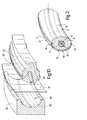
- Shell 10 is a substantially circular, closed-ring shell made of one continuous piece with no joins, is located along a radially outer peripheral edge 12 of steering wheel 1, is fitted about wheel 8 of supporting structure 2, along the whole of peripheral edge 12, and is bounded by a lateral wall 13 having a C-shaped cross section extending at least 180° about wheel 8, and having two opposite, facing, ring-shaped peripheral edges 14 substantially parallel to each other.
- steering wheel 1 is made from a pack 15 of multilayer composite material comprising a base layer 16 of raw, rough-surfaced wood, one or more resin-impregnated substrates alternating with sheets of wood, and outer layer 11.
- Pack 15 is cut into a substantially flat strip 17 (Figure 3) elongated along a substantially straight axis A; and strip 17 is then curved along axis A to form a curved collar-like member 18 with a predetermined radius of curvature ( Figure 4). More specifically, strip 17 is wound and closed into a ring to form a tubular collar, by overlapping and securing (e.g. stapling) longitudinally opposite end portions 19 of strip 17.
- overlapping and securing e.g. stapling
- a mold 25 comprising an annular matrix 26 and an annular punch 27, which are substantially circular and concentric and face each other to define an annular chamber 28 for insertion of member 18; matrix 26 is located radially outwards and has a forming seat 29; and punch 27 is located radially inwards, and cooperates with matrix 26 to impart the shape of seat 29 to member 18.
- Matrix 26 and punch 27 comprise respective numbers of circumferentially side by side sectors, are movable radially as a whole with respect to each other, and cooperate to press member 18.
- the process of forming shell 10 comprises a pressing step preferably conducted in two substantially perpendicular pressing directions.
- Member 18 is first pressed radially between matrix 26 and punch 27 in a first pressing direction (shown schematically by the arrows in Figure 6) radial with respect to member 18.
- mold 25 comprises two clamp plates 30 located on opposite sides of member 18, movable towards each other, and having respective annular projections 31 which cooperate with punch 27 to press peripheral edges 14 onto punch 27 ( Figure 8).
- the pressing step is accompanied by a trimming step, in which, in addition to being curved towards each other, peripheral edges 14 are also trimmed.
- the trimming step is performed in the same mold 25; for which purpose, projections 31 have respective trimming edges 32, which cooperate with matrix 26 and punch 27 to trim peripheral edges 14 and detach the trimming scrap from shell 10 ( Figure 8).
- Mold 25 also comprises a known heating system (not shown), so that the pressing step is performed in the presence of heat to polymerize and/or cross-link the resin in the multilayer composite material from which shell 10 is made. After a given time long enough to complete polymerization/cross-linking and formation of shell 10, mold 25 is opened to extract shell 10 ( Figure 9).
- shell 10 made in one single piece with no joins, is applied whole to supporting structure 2, in particular along peripheral edge 12, as shown schematically in Figure 11.
- Supporting structure 2 and shell 10 are inserted inside an injection mold 35 comprising, between supporting structure 2 and shell 10, clearances 36 enabling shell 10 to be fitted to peripheral edge 12 and about wheel 8.
- injection mold 35 may be loaded with a supporting structure 2 defined solely by core 4, with no layer 5 (unfoamed supporting structure); in which case, clearances 36 are defined by the space (as yet empty) eventually filled with the polymer foam material 6 forming layer 5. Clearances 36 are defined, in particular, by an inner cavity 37 of injection mold 35 bounded by mutually cooperating members 38 of injection mold 35 movable with respect to one another.
- a supporting structure 2 may be used comprising core 4, and an incomplete layer 5 in which clearances 36 for fitting shell 10 to wheel 8 are formed (partly foamed supporting structure).
- shell 10 is placed about wheel 8 inside injection mold 35. Supporting structure 2 and shell 10 are centred with respect to each other and held in position by appropriate stops (not shown).
- Polymer foam material 6 (e.g. polyurethane foam) is then injected into injection mold 35 by one or more nozzles 39 communicating with clearances 36, and fills clearances 36 to form layer 5 and at the same time secure shell 10 integrally to supporting structure 2, both by mechanical interference and by polymer material 6 adhering to the inner surface of shell 10 (i.e. to rough-wood base layer 16).
- polymer material 6 instead of polymer material 6, another adhesive and/or expanding polymer material may be injected, providing it is capable of filling clearances 36 and connecting shell 10 integrally to supporting structure 2.
- shell 10 is cut into two mating annular half-shells 40 (Figure 12).
- the cutting step is advantageously performed in mold 25, simultaneously with the pressing step.
- matrix 26 and punch 27 have respective members 42, 43 which cooperate to cut shell 10 into two half-shells 40.
- matrix 26 has an annular edge 42 projecting centrally from seat 29, and punch 27 has a corresponding annular cavity 43.
- shell 10 is cut into two half-shells 40, these may be fitted to supporting structure 2, on opposite sides of wheel 8, without interfering with layer 5, and may therefore be simply glued to each other and to layer 5 in known manner.
- Supporting structure 2 may obviously also be fitted with only one half-shell 40, as shown in Figure 13.
Landscapes
- Engineering & Computer Science (AREA)
- Chemical & Material Sciences (AREA)
- Combustion & Propulsion (AREA)
- Transportation (AREA)
- Mechanical Engineering (AREA)
- Steering Controls (AREA)
Priority Applications (1)
| Application Number | Priority Date | Filing Date | Title |
|---|---|---|---|
| EP05425124A EP1698537A1 (de) | 2005-03-04 | 2005-03-04 | Lenkrad mit hochwertiger Deckschicht |
Applications Claiming Priority (1)
| Application Number | Priority Date | Filing Date | Title |
|---|---|---|---|
| EP05425124A EP1698537A1 (de) | 2005-03-04 | 2005-03-04 | Lenkrad mit hochwertiger Deckschicht |
Publications (1)
| Publication Number | Publication Date |
|---|---|
| EP1698537A1 true EP1698537A1 (de) | 2006-09-06 |
Family
ID=34943083
Family Applications (1)
| Application Number | Title | Priority Date | Filing Date |
|---|---|---|---|
| EP05425124A Withdrawn EP1698537A1 (de) | 2005-03-04 | 2005-03-04 | Lenkrad mit hochwertiger Deckschicht |
Country Status (1)
| Country | Link |
|---|---|
| EP (1) | EP1698537A1 (de) |
Cited By (1)
| Publication number | Priority date | Publication date | Assignee | Title |
|---|---|---|---|---|
| ES2541811A1 (es) * | 2014-01-24 | 2015-07-24 | Manprocar Vigo, S.L. | Método de fabricación de elementos de madera para forrado de volantes de vehículos |
Citations (3)
| Publication number | Priority date | Publication date | Assignee | Title |
|---|---|---|---|---|
| DE1630913A1 (de) * | 1967-03-21 | 1970-05-27 | Ernst Pelz | Ring,insbesondere fuer ein Lenk- oder Steuerrad eines Fahrzeugs |
| JPH11291205A (ja) * | 1998-04-03 | 1999-10-26 | Toyo Yuatsu Kogyo:Kk | 木材成形方法およびパイプ状成形物の製造方法 |
| EP1029770A1 (de) * | 1999-02-19 | 2000-08-23 | Breed Automotive Technology, Inc. | Herstellungsverfahren für ein Kraftfahrzeuglenkrad mit einer äusseren Hülle aus Verbundmaterial und dadurch erlangtes Lenkrad |
-
2005
- 2005-03-04 EP EP05425124A patent/EP1698537A1/de not_active Withdrawn
Patent Citations (3)
| Publication number | Priority date | Publication date | Assignee | Title |
|---|---|---|---|---|
| DE1630913A1 (de) * | 1967-03-21 | 1970-05-27 | Ernst Pelz | Ring,insbesondere fuer ein Lenk- oder Steuerrad eines Fahrzeugs |
| JPH11291205A (ja) * | 1998-04-03 | 1999-10-26 | Toyo Yuatsu Kogyo:Kk | 木材成形方法およびパイプ状成形物の製造方法 |
| EP1029770A1 (de) * | 1999-02-19 | 2000-08-23 | Breed Automotive Technology, Inc. | Herstellungsverfahren für ein Kraftfahrzeuglenkrad mit einer äusseren Hülle aus Verbundmaterial und dadurch erlangtes Lenkrad |
Non-Patent Citations (1)
| Title |
|---|
| PATENT ABSTRACTS OF JAPAN vol. 2000, no. 01 31 January 2000 (2000-01-31) * |
Cited By (1)
| Publication number | Priority date | Publication date | Assignee | Title |
|---|---|---|---|---|
| ES2541811A1 (es) * | 2014-01-24 | 2015-07-24 | Manprocar Vigo, S.L. | Método de fabricación de elementos de madera para forrado de volantes de vehículos |
Similar Documents
| Publication | Publication Date | Title |
|---|---|---|
| EP0985590B1 (de) | Verfahren zum Herstellen von Kraftfahrzeuglenkrädern, insbesondere Lenkräder mit einer Hülle aus hochwertigem Material, und durch ein solches Verfahren hergestellte Lenkräder | |
| EP1755854B1 (de) | Verfahren und werkzeug zur herstellung von zierkomponenten für kraftfahrzeuginnenräume | |
| JP2817038B2 (ja) | 天然産物から成る上張りを持つ車両用かじ取りハンドルの製造方法 | |
| JP2964914B2 (ja) | ステアリングホイールの製法 | |
| US6282982B1 (en) | Steering wheel | |
| US8047097B2 (en) | Steering wheel and method of making | |
| EP1162125B1 (de) | Verfahren zur Herstellung von Kraftfahrzeuglenkrädern, insbesondere Holzlenkräder mit einer Hülle aus hochwertigem Material, und durch ein solches Verfahren hergestellte Lenkräder | |
| US6279419B1 (en) | Steering wheel | |
| CN106232316A (zh) | 用于汽车内饰配件的多层模制体和生产这种模制体的方法 | |
| US4891085A (en) | Method of making an automobile roof cap | |
| KR101544817B1 (ko) | 트림용 우드 포일 및 그의 제조방법 | |
| US20030089192A1 (en) | Steering wheel and manufacturing method therefor | |
| WO1993001930A1 (en) | A vehicle wheel and a method of fabricating same | |
| JPS59201814A (ja) | 車両用内装板の端部加工方法 | |
| US20130266783A1 (en) | Method for producing moldings having different surface materials | |
| JP3039755B2 (ja) | 自動車用内装部品の製造方法 | |
| JP2001030915A (ja) | ステアリング用グリップ部材の突板貼り合せ方法 | |
| CA2083736A1 (en) | Method of producing veneer-faced moulded items | |
| JPS63176132A (ja) | 自動車用ドアトリムの製造方法 | |
| JP6635576B2 (ja) | ステアリングホイール及びその製造方法 | |
| JPS6039552B2 (ja) | パツド材入り内装部品の端末処理方法 | |
| JPS6242779B2 (de) | ||
| JPS61235111A (ja) | 積層成形体の製造方法 | |
| JPH11254552A (ja) | ステアリングホイ−ルの製造方法 | |
| KR20180024415A (ko) | 스티어링 휠용 인테리어 마감재 |
Legal Events
| Date | Code | Title | Description |
|---|---|---|---|
| PUAI | Public reference made under article 153(3) epc to a published international application that has entered the european phase |
Free format text: ORIGINAL CODE: 0009012 |
|
| AK | Designated contracting states |
Kind code of ref document: A1 Designated state(s): AT BE BG CH CY CZ DE DK EE ES FI FR GB GR HU IE IS IT LI LT LU MC NL PL PT RO SE SI SK TR |
|
| AX | Request for extension of the european patent |
Extension state: AL BA HR LV MK YU |
|
| 17P | Request for examination filed |
Effective date: 20070305 |
|
| AKX | Designation fees paid |
Designated state(s): AT BE BG CH CY CZ DE DK EE ES FI FR GB GR HU IE IS IT LI LT LU MC NL PL PT RO SE SI SK TR |
|
| 17Q | First examination report despatched |
Effective date: 20070426 |
|
| STAA | Information on the status of an ep patent application or granted ep patent |
Free format text: STATUS: THE APPLICATION IS DEEMED TO BE WITHDRAWN |
|
| 18D | Application deemed to be withdrawn |
Effective date: 20091001 |