EP1699103A1 - Procede et appareil permettant de purifier l'air destine a une pile a combustible et pile a combustible - Google Patents
Procede et appareil permettant de purifier l'air destine a une pile a combustible et pile a combustible Download PDFInfo
- Publication number
- EP1699103A1 EP1699103A1 EP04807353A EP04807353A EP1699103A1 EP 1699103 A1 EP1699103 A1 EP 1699103A1 EP 04807353 A EP04807353 A EP 04807353A EP 04807353 A EP04807353 A EP 04807353A EP 1699103 A1 EP1699103 A1 EP 1699103A1
- Authority
- EP
- European Patent Office
- Prior art keywords
- air
- fuel cell
- fuel
- cell according
- decontamination
- Prior art date
- Legal status (The legal status is an assumption and is not a legal conclusion. Google has not performed a legal analysis and makes no representation as to the accuracy of the status listed.)
- Granted
Links
- 239000000446 fuel Substances 0.000 title claims abstract description 83
- 238000000034 method Methods 0.000 title claims abstract description 36
- 239000012535 impurity Substances 0.000 claims abstract description 34
- 150000003464 sulfur compounds Chemical class 0.000 claims abstract description 31
- 238000005202 decontamination Methods 0.000 claims abstract description 22
- 230000003588 decontaminative effect Effects 0.000 claims abstract description 22
- 239000000356 contaminant Substances 0.000 claims abstract 4
- RAHZWNYVWXNFOC-UHFFFAOYSA-N Sulphur dioxide Chemical compound O=S=O RAHZWNYVWXNFOC-UHFFFAOYSA-N 0.000 claims description 107
- 238000004140 cleaning Methods 0.000 claims description 62
- 239000011230 binding agent Substances 0.000 claims description 50
- 239000003463 adsorbent Substances 0.000 claims description 47
- 239000002245 particle Substances 0.000 claims description 46
- OKTJSMMVPCPJKN-UHFFFAOYSA-N Carbon Chemical compound [C] OKTJSMMVPCPJKN-UHFFFAOYSA-N 0.000 claims description 37
- 239000000463 material Substances 0.000 claims description 37
- 239000003054 catalyst Substances 0.000 claims description 17
- 229920005830 Polyurethane Foam Polymers 0.000 claims description 10
- 239000011496 polyurethane foam Substances 0.000 claims description 10
- -1 alkaline earth metal salts Chemical class 0.000 claims description 8
- 230000000717 retained effect Effects 0.000 claims description 8
- 239000003610 charcoal Substances 0.000 claims description 5
- 150000001875 compounds Chemical class 0.000 claims description 5
- 239000011347 resin Substances 0.000 claims description 4
- 229920005989 resin Polymers 0.000 claims description 4
- 238000011144 upstream manufacturing Methods 0.000 claims description 3
- 239000010457 zeolite Substances 0.000 claims description 3
- 229910052784 alkaline earth metal Inorganic materials 0.000 claims description 2
- 229910001860 alkaline earth metal hydroxide Inorganic materials 0.000 claims description 2
- 239000004927 clay Substances 0.000 claims description 2
- 239000000835 fiber Substances 0.000 claims description 2
- 229910052751 metal Inorganic materials 0.000 claims description 2
- 239000002184 metal Substances 0.000 claims description 2
- 229910000000 metal hydroxide Inorganic materials 0.000 claims description 2
- 150000004692 metal hydroxides Chemical class 0.000 claims description 2
- 150000003839 salts Chemical class 0.000 claims description 2
- 239000013522 chelant Substances 0.000 claims 2
- 235000013162 Cocos nucifera Nutrition 0.000 claims 1
- 244000060011 Cocos nucifera Species 0.000 claims 1
- GWEVSGVZZGPLCZ-UHFFFAOYSA-N Titan oxide Chemical compound O=[Ti]=O GWEVSGVZZGPLCZ-UHFFFAOYSA-N 0.000 claims 1
- 239000010953 base metal Substances 0.000 claims 1
- 238000006243 chemical reaction Methods 0.000 claims 1
- 239000003795 chemical substances by application Substances 0.000 claims 1
- 239000002781 deodorant agent Substances 0.000 claims 1
- 238000006386 neutralization reaction Methods 0.000 claims 1
- 230000001590 oxidative effect Effects 0.000 claims 1
- 239000011301 petroleum pitch Substances 0.000 claims 1
- 239000011941 photocatalyst Substances 0.000 claims 1
- 239000000126 substance Substances 0.000 claims 1
- 239000004094 surface-active agent Substances 0.000 claims 1
- OGIDPMRJRNCKJF-UHFFFAOYSA-N titanium oxide Inorganic materials [Ti]=O OGIDPMRJRNCKJF-UHFFFAOYSA-N 0.000 claims 1
- 239000002023 wood Substances 0.000 claims 1
- 210000004027 cell Anatomy 0.000 description 63
- 239000007789 gas Substances 0.000 description 38
- 239000002585 base Substances 0.000 description 32
- 238000012360 testing method Methods 0.000 description 18
- 230000007423 decrease Effects 0.000 description 15
- 238000001179 sorption measurement Methods 0.000 description 11
- 230000003247 decreasing effect Effects 0.000 description 8
- 238000005259 measurement Methods 0.000 description 8
- BWHMMNNQKKPAPP-UHFFFAOYSA-L potassium carbonate Chemical compound [K+].[K+].[O-]C([O-])=O BWHMMNNQKKPAPP-UHFFFAOYSA-L 0.000 description 8
- JOYRKODLDBILNP-UHFFFAOYSA-N Ethyl urethane Chemical compound CCOC(N)=O JOYRKODLDBILNP-UHFFFAOYSA-N 0.000 description 7
- 239000004745 nonwoven fabric Substances 0.000 description 7
- UFHFLCQGNIYNRP-UHFFFAOYSA-N Hydrogen Chemical compound [H][H] UFHFLCQGNIYNRP-UHFFFAOYSA-N 0.000 description 5
- 238000005470 impregnation Methods 0.000 description 5
- 238000004519 manufacturing process Methods 0.000 description 5
- 238000010248 power generation Methods 0.000 description 5
- RTZKZFJDLAIYFH-UHFFFAOYSA-N Diethyl ether Chemical compound CCOCC RTZKZFJDLAIYFH-UHFFFAOYSA-N 0.000 description 4
- QVGXLLKOCUKJST-UHFFFAOYSA-N atomic oxygen Chemical compound [O] QVGXLLKOCUKJST-UHFFFAOYSA-N 0.000 description 4
- 230000000052 comparative effect Effects 0.000 description 4
- KIQKWYUGPPFMBV-UHFFFAOYSA-N diisocyanatomethane Chemical compound O=C=NCN=C=O KIQKWYUGPPFMBV-UHFFFAOYSA-N 0.000 description 4
- 230000000694 effects Effects 0.000 description 4
- 239000000839 emulsion Substances 0.000 description 4
- 239000002737 fuel gas Substances 0.000 description 4
- 239000003960 organic solvent Substances 0.000 description 4
- 229910052760 oxygen Inorganic materials 0.000 description 4
- 239000001301 oxygen Substances 0.000 description 4
- 239000005518 polymer electrolyte Substances 0.000 description 4
- 239000011148 porous material Substances 0.000 description 4
- 229910000027 potassium carbonate Inorganic materials 0.000 description 4
- 239000007787 solid Substances 0.000 description 4
- KWYUFKZDYYNOTN-UHFFFAOYSA-M Potassium hydroxide Chemical compound [OH-].[K+] KWYUFKZDYYNOTN-UHFFFAOYSA-M 0.000 description 3
- HEMHJVSKTPXQMS-UHFFFAOYSA-M Sodium hydroxide Chemical compound [OH-].[Na+] HEMHJVSKTPXQMS-UHFFFAOYSA-M 0.000 description 3
- 238000001514 detection method Methods 0.000 description 3
- 239000001257 hydrogen Substances 0.000 description 3
- 229910052739 hydrogen Inorganic materials 0.000 description 3
- 230000001771 impaired effect Effects 0.000 description 3
- 229910000510 noble metal Inorganic materials 0.000 description 3
- BASFCYQUMIYNBI-UHFFFAOYSA-N platinum Substances [Pt] BASFCYQUMIYNBI-UHFFFAOYSA-N 0.000 description 3
- 238000005507 spraying Methods 0.000 description 3
- 229910052815 sulfur oxide Inorganic materials 0.000 description 3
- NWUYHJFMYQTDRP-UHFFFAOYSA-N 1,2-bis(ethenyl)benzene;1-ethenyl-2-ethylbenzene;styrene Chemical compound C=CC1=CC=CC=C1.CCC1=CC=CC=C1C=C.C=CC1=CC=CC=C1C=C NWUYHJFMYQTDRP-UHFFFAOYSA-N 0.000 description 2
- QTBSBXVTEAMEQO-UHFFFAOYSA-N Acetic acid Chemical compound CC(O)=O QTBSBXVTEAMEQO-UHFFFAOYSA-N 0.000 description 2
- IJGRMHOSHXDMSA-UHFFFAOYSA-N Atomic nitrogen Chemical compound N#N IJGRMHOSHXDMSA-UHFFFAOYSA-N 0.000 description 2
- VTYYLEPIZMXCLO-UHFFFAOYSA-L Calcium carbonate Chemical compound [Ca+2].[O-]C([O-])=O VTYYLEPIZMXCLO-UHFFFAOYSA-L 0.000 description 2
- CURLTUGMZLYLDI-UHFFFAOYSA-N Carbon dioxide Chemical compound O=C=O CURLTUGMZLYLDI-UHFFFAOYSA-N 0.000 description 2
- BVKZGUZCCUSVTD-UHFFFAOYSA-L Carbonate Chemical compound [O-]C([O-])=O BVKZGUZCCUSVTD-UHFFFAOYSA-L 0.000 description 2
- NBIIXXVUZAFLBC-UHFFFAOYSA-N Phosphoric acid Chemical compound OP(O)(O)=O NBIIXXVUZAFLBC-UHFFFAOYSA-N 0.000 description 2
- 239000004743 Polypropylene Substances 0.000 description 2
- CDBYLPFSWZWCQE-UHFFFAOYSA-L Sodium Carbonate Chemical compound [Na+].[Na+].[O-]C([O-])=O CDBYLPFSWZWCQE-UHFFFAOYSA-L 0.000 description 2
- 238000001723 curing Methods 0.000 description 2
- 230000006866 deterioration Effects 0.000 description 2
- 238000010586 diagram Methods 0.000 description 2
- 238000002474 experimental method Methods 0.000 description 2
- 239000004744 fabric Substances 0.000 description 2
- 239000012530 fluid Substances 0.000 description 2
- 239000006260 foam Substances 0.000 description 2
- 230000007062 hydrolysis Effects 0.000 description 2
- 238000006460 hydrolysis reaction Methods 0.000 description 2
- 239000003456 ion exchange resin Substances 0.000 description 2
- 229920003303 ion-exchange polymer Polymers 0.000 description 2
- 229910052697 platinum Inorganic materials 0.000 description 2
- 229920001155 polypropylene Polymers 0.000 description 2
- 239000000843 powder Substances 0.000 description 2
- 238000012545 processing Methods 0.000 description 2
- ZOXJGFHDIHLPTG-UHFFFAOYSA-N Boron Chemical compound [B] ZOXJGFHDIHLPTG-UHFFFAOYSA-N 0.000 description 1
- 239000004215 Carbon black (E152) Substances 0.000 description 1
- UGFAIRIUMAVXCW-UHFFFAOYSA-N Carbon monoxide Chemical compound [O+]#[C-] UGFAIRIUMAVXCW-UHFFFAOYSA-N 0.000 description 1
- WSFSSNUMVMOOMR-UHFFFAOYSA-N Formaldehyde Chemical compound O=C WSFSSNUMVMOOMR-UHFFFAOYSA-N 0.000 description 1
- 239000004642 Polyimide Substances 0.000 description 1
- 239000004721 Polyphenylene oxide Substances 0.000 description 1
- 229910000929 Ru alloy Inorganic materials 0.000 description 1
- VYPSYNLAJGMNEJ-UHFFFAOYSA-N Silicium dioxide Chemical compound O=[Si]=O VYPSYNLAJGMNEJ-UHFFFAOYSA-N 0.000 description 1
- NINIDFKCEFEMDL-UHFFFAOYSA-N Sulfur Chemical compound [S] NINIDFKCEFEMDL-UHFFFAOYSA-N 0.000 description 1
- LSNNMFCWUKXFEE-UHFFFAOYSA-N Sulfurous acid Chemical compound OS(O)=O LSNNMFCWUKXFEE-UHFFFAOYSA-N 0.000 description 1
- 229910021536 Zeolite Inorganic materials 0.000 description 1
- 230000002378 acidificating effect Effects 0.000 description 1
- NIXOWILDQLNWCW-UHFFFAOYSA-N acrylic acid group Chemical group C(C=C)(=O)O NIXOWILDQLNWCW-UHFFFAOYSA-N 0.000 description 1
- 239000003513 alkali Substances 0.000 description 1
- PNEYBMLMFCGWSK-UHFFFAOYSA-N aluminium oxide Inorganic materials [O-2].[O-2].[O-2].[Al+3].[Al+3] PNEYBMLMFCGWSK-UHFFFAOYSA-N 0.000 description 1
- 229910000147 aluminium phosphate Inorganic materials 0.000 description 1
- 238000005422 blasting Methods 0.000 description 1
- 229910052796 boron Inorganic materials 0.000 description 1
- 229910000019 calcium carbonate Inorganic materials 0.000 description 1
- AXCZMVOFGPJBDE-UHFFFAOYSA-L calcium dihydroxide Chemical compound [OH-].[OH-].[Ca+2] AXCZMVOFGPJBDE-UHFFFAOYSA-L 0.000 description 1
- 239000000920 calcium hydroxide Substances 0.000 description 1
- 229910001861 calcium hydroxide Inorganic materials 0.000 description 1
- 238000004364 calculation method Methods 0.000 description 1
- 239000001569 carbon dioxide Substances 0.000 description 1
- 229910002092 carbon dioxide Inorganic materials 0.000 description 1
- 229910002091 carbon monoxide Inorganic materials 0.000 description 1
- 210000000170 cell membrane Anatomy 0.000 description 1
- 238000002485 combustion reaction Methods 0.000 description 1
- 238000000354 decomposition reaction Methods 0.000 description 1
- 230000007547 defect Effects 0.000 description 1
- 230000002542 deteriorative effect Effects 0.000 description 1
- 238000011161 development Methods 0.000 description 1
- HNPSIPDUKPIQMN-UHFFFAOYSA-N dioxosilane;oxo(oxoalumanyloxy)alumane Chemical compound O=[Si]=O.O=[Al]O[Al]=O HNPSIPDUKPIQMN-UHFFFAOYSA-N 0.000 description 1
- 238000001035 drying Methods 0.000 description 1
- 239000000428 dust Substances 0.000 description 1
- 238000010410 dusting Methods 0.000 description 1
- 238000003487 electrochemical reaction Methods 0.000 description 1
- 238000005516 engineering process Methods 0.000 description 1
- 150000002148 esters Chemical class 0.000 description 1
- 238000002795 fluorescence method Methods 0.000 description 1
- 239000011521 glass Substances 0.000 description 1
- 239000003365 glass fiber Substances 0.000 description 1
- 239000012943 hotmelt Substances 0.000 description 1
- 229930195733 hydrocarbon Natural products 0.000 description 1
- 150000002430 hydrocarbons Chemical class 0.000 description 1
- 238000009434 installation Methods 0.000 description 1
- 239000012948 isocyanate Substances 0.000 description 1
- 150000002513 isocyanates Chemical class 0.000 description 1
- ZLNQQNXFFQJAID-UHFFFAOYSA-L magnesium carbonate Chemical compound [Mg+2].[O-]C([O-])=O ZLNQQNXFFQJAID-UHFFFAOYSA-L 0.000 description 1
- 239000001095 magnesium carbonate Substances 0.000 description 1
- 229910000021 magnesium carbonate Inorganic materials 0.000 description 1
- VTHJTEIRLNZDEV-UHFFFAOYSA-L magnesium dihydroxide Chemical compound [OH-].[OH-].[Mg+2] VTHJTEIRLNZDEV-UHFFFAOYSA-L 0.000 description 1
- 239000000347 magnesium hydroxide Substances 0.000 description 1
- 229910001862 magnesium hydroxide Inorganic materials 0.000 description 1
- 230000014759 maintenance of location Effects 0.000 description 1
- 239000012528 membrane Substances 0.000 description 1
- 238000013008 moisture curing Methods 0.000 description 1
- 229910052757 nitrogen Inorganic materials 0.000 description 1
- 229910052763 palladium Inorganic materials 0.000 description 1
- 230000035699 permeability Effects 0.000 description 1
- 229920003023 plastic Polymers 0.000 description 1
- 239000004033 plastic Substances 0.000 description 1
- CFQCIHVMOFOCGH-UHFFFAOYSA-N platinum ruthenium Chemical compound [Ru].[Pt] CFQCIHVMOFOCGH-UHFFFAOYSA-N 0.000 description 1
- 239000002574 poison Substances 0.000 description 1
- 231100000614 poison Toxicity 0.000 description 1
- 229920000728 polyester Polymers 0.000 description 1
- 229920000570 polyether Polymers 0.000 description 1
- 229920001721 polyimide Polymers 0.000 description 1
- 229920000642 polymer Polymers 0.000 description 1
- 229920006254 polymer film Polymers 0.000 description 1
- 239000012495 reaction gas Substances 0.000 description 1
- 238000002407 reforming Methods 0.000 description 1
- 229910052707 ruthenium Inorganic materials 0.000 description 1
- 239000000741 silica gel Substances 0.000 description 1
- 229910002027 silica gel Inorganic materials 0.000 description 1
- 229910000029 sodium carbonate Inorganic materials 0.000 description 1
- 239000002904 solvent Substances 0.000 description 1
- 239000007921 spray Substances 0.000 description 1
- 229910052717 sulfur Inorganic materials 0.000 description 1
- 239000011593 sulfur Substances 0.000 description 1
Images

Classifications
-
- B—PERFORMING OPERATIONS; TRANSPORTING
- B01—PHYSICAL OR CHEMICAL PROCESSES OR APPARATUS IN GENERAL
- B01D—SEPARATION
- B01D53/00—Separation of gases or vapours; Recovering vapours of volatile solvents from gases; Chemical or biological purification of waste gases, e.g. engine exhaust gases, smoke, fumes, flue gases, aerosols
- B01D53/02—Separation of gases or vapours; Recovering vapours of volatile solvents from gases; Chemical or biological purification of waste gases, e.g. engine exhaust gases, smoke, fumes, flue gases, aerosols by adsorption, e.g. preparative gas chromatography
- B01D53/04—Separation of gases or vapours; Recovering vapours of volatile solvents from gases; Chemical or biological purification of waste gases, e.g. engine exhaust gases, smoke, fumes, flue gases, aerosols by adsorption, e.g. preparative gas chromatography with stationary adsorbents
-
- H—ELECTRICITY
- H01—ELECTRIC ELEMENTS
- H01M—PROCESSES OR MEANS, e.g. BATTERIES, FOR THE DIRECT CONVERSION OF CHEMICAL ENERGY INTO ELECTRICAL ENERGY
- H01M8/00—Fuel cells; Manufacture thereof
- H01M8/06—Combination of fuel cells with means for production of reactants or for treatment of residues
- H01M8/0662—Treatment of gaseous reactants or gaseous residues, e.g. cleaning
-
- H—ELECTRICITY
- H01—ELECTRIC ELEMENTS
- H01M—PROCESSES OR MEANS, e.g. BATTERIES, FOR THE DIRECT CONVERSION OF CHEMICAL ENERGY INTO ELECTRICAL ENERGY
- H01M8/00—Fuel cells; Manufacture thereof
- H01M8/06—Combination of fuel cells with means for production of reactants or for treatment of residues
- H01M8/0662—Treatment of gaseous reactants or gaseous residues, e.g. cleaning
- H01M8/0675—Removal of sulfur
-
- B—PERFORMING OPERATIONS; TRANSPORTING
- B01—PHYSICAL OR CHEMICAL PROCESSES OR APPARATUS IN GENERAL
- B01D—SEPARATION
- B01D2253/00—Adsorbents used in seperation treatment of gases and vapours
- B01D2253/10—Inorganic adsorbents
- B01D2253/102—Carbon
-
- B—PERFORMING OPERATIONS; TRANSPORTING
- B01—PHYSICAL OR CHEMICAL PROCESSES OR APPARATUS IN GENERAL
- B01D—SEPARATION
- B01D2253/00—Adsorbents used in seperation treatment of gases and vapours
- B01D2253/10—Inorganic adsorbents
- B01D2253/106—Silica or silicates
- B01D2253/108—Zeolites
-
- B—PERFORMING OPERATIONS; TRANSPORTING
- B01—PHYSICAL OR CHEMICAL PROCESSES OR APPARATUS IN GENERAL
- B01D—SEPARATION
- B01D2253/00—Adsorbents used in seperation treatment of gases and vapours
- B01D2253/10—Inorganic adsorbents
- B01D2253/106—Silica or silicates
- B01D2253/11—Clays
-
- B—PERFORMING OPERATIONS; TRANSPORTING
- B01—PHYSICAL OR CHEMICAL PROCESSES OR APPARATUS IN GENERAL
- B01D—SEPARATION
- B01D2253/00—Adsorbents used in seperation treatment of gases and vapours
- B01D2253/20—Organic adsorbents
- B01D2253/202—Polymeric adsorbents
-
- B—PERFORMING OPERATIONS; TRANSPORTING
- B01—PHYSICAL OR CHEMICAL PROCESSES OR APPARATUS IN GENERAL
- B01D—SEPARATION
- B01D2253/00—Adsorbents used in seperation treatment of gases and vapours
- B01D2253/20—Organic adsorbents
- B01D2253/206—Ion exchange resins
-
- B—PERFORMING OPERATIONS; TRANSPORTING
- B01—PHYSICAL OR CHEMICAL PROCESSES OR APPARATUS IN GENERAL
- B01D—SEPARATION
- B01D2253/00—Adsorbents used in seperation treatment of gases and vapours
- B01D2253/30—Physical properties of adsorbents
- B01D2253/34—Specific shapes
- B01D2253/342—Monoliths
-
- B—PERFORMING OPERATIONS; TRANSPORTING
- B01—PHYSICAL OR CHEMICAL PROCESSES OR APPARATUS IN GENERAL
- B01D—SEPARATION
- B01D2257/00—Components to be removed
- B01D2257/30—Sulfur compounds
- B01D2257/302—Sulfur oxides
-
- B—PERFORMING OPERATIONS; TRANSPORTING
- B01—PHYSICAL OR CHEMICAL PROCESSES OR APPARATUS IN GENERAL
- B01D—SEPARATION
- B01D2257/00—Components to be removed
- B01D2257/30—Sulfur compounds
- B01D2257/304—Hydrogen sulfide
-
- B—PERFORMING OPERATIONS; TRANSPORTING
- B01—PHYSICAL OR CHEMICAL PROCESSES OR APPARATUS IN GENERAL
- B01D—SEPARATION
- B01D2257/00—Components to be removed
- B01D2257/90—Odorous compounds not provided for in groups B01D2257/00 - B01D2257/708
-
- B—PERFORMING OPERATIONS; TRANSPORTING
- B01—PHYSICAL OR CHEMICAL PROCESSES OR APPARATUS IN GENERAL
- B01D—SEPARATION
- B01D2258/00—Sources of waste gases
- B01D2258/02—Other waste gases
- B01D2258/0208—Other waste gases from fuel cells
-
- H—ELECTRICITY
- H01—ELECTRIC ELEMENTS
- H01M—PROCESSES OR MEANS, e.g. BATTERIES, FOR THE DIRECT CONVERSION OF CHEMICAL ENERGY INTO ELECTRICAL ENERGY
- H01M8/00—Fuel cells; Manufacture thereof
- H01M8/06—Combination of fuel cells with means for production of reactants or for treatment of residues
- H01M8/0662—Treatment of gaseous reactants or gaseous residues, e.g. cleaning
- H01M8/0687—Reactant purification by the use of membranes or filters
-
- Y—GENERAL TAGGING OF NEW TECHNOLOGICAL DEVELOPMENTS; GENERAL TAGGING OF CROSS-SECTIONAL TECHNOLOGIES SPANNING OVER SEVERAL SECTIONS OF THE IPC; TECHNICAL SUBJECTS COVERED BY FORMER USPC CROSS-REFERENCE ART COLLECTIONS [XRACs] AND DIGESTS
- Y02—TECHNOLOGIES OR APPLICATIONS FOR MITIGATION OR ADAPTATION AGAINST CLIMATE CHANGE
- Y02E—REDUCTION OF GREENHOUSE GAS [GHG] EMISSIONS, RELATED TO ENERGY GENERATION, TRANSMISSION OR DISTRIBUTION
- Y02E60/00—Enabling technologies; Technologies with a potential or indirect contribution to GHG emissions mitigation
- Y02E60/30—Hydrogen technology
- Y02E60/50—Fuel cells
Definitions
- the present invention relates to methods and devices for treating fuel-cell air to remove certain components which are contained in air to be supplied to fuel cells and cause decreases in the cell voltage of the fuel cells. More specifically, the present invention relates to methods and devices for cleaning fuel-cell air to maintain the characteristics of fuel cells and extend the lifetime thereof by efficiently removing certain components, such as sulfur dioxide (SO 2 ), which are contained in the fuel-cell air and cause decreases in the cell voltage of the fuel cells.
- SO 2 sulfur dioxide
- the present invention further relates to fuel cells which are supplied with the thus-cleaned air.
- a fuel cell is a device for generating an electromotive force by an electrochemical reaction between hydrogen and oxygen. It is known that when impurities are contained in a fluid of fuel or air to be supplied to the fuel cell, an electrode catalyst is poisoned resulting in a decrease in the cell voltage of the fuel cell; this, as a result, causes decreases in the generation efficiency and the lifetime of the fuel cell.
- Various methods for removing the impurities in the air or the fuel to be supplied to the fuel cell have been proposed.
- Japanese Unexamined Patent Application Publication No. 2000-277139 discloses a method for removing impurities such as organic solvents in air by passing the air through a heated combustion catalyst layer to burn and decompose the impurities.
- Japanese Unexamined Patent Application Publication No. 2000-327305 discloses a method for adsorbing and removing impurities such as SO x and NO x in air to be used for reforming fuel gas by treating the air with activated charcoal.
- Japanese Unexamined Patent Application Publication No. 2001-313057 discloses a method for removing gas impurities such as acidic gas and alkaline gas from air or hydrogen gas by bringing the gas or the hydrogen gas into contact with a filter having an ion-exchange resin.
- Japanese Unexamined Patent Application Publication No. 2002-93452 discloses a method for removing impurities such as sulfurous acid gas in fuel gas by bringing the fuel gas into contact with fused carbonate.
- a cleaning filter for removing gas which poisons a catalyst material used in a solid-polymer electrolytic film or an electrode (the gas is referred to as "fuel-cell electromotive-force-reducing impurities" in the present invention) is used.
- Japanese Unexamined Patent Application Publication No. 2003-297410 proposes a filter including a three-dimensional reticulate skeleton structure and a material retained in the three-dimensional reticulate skeleton structure for decomposing or adsorbing impurities.
- the fuel-cell electromotive-force-reducing impurities are removed from the air to be supplied to the fuel cell by being decomposed or adsorbed by the material retained in the three-dimensional reticulate skeleton structure. Since the decomposing or adsorbing material is retained in the three-dimensional reticulate skeleton structure, the specific surface of the material is large and the fuel-cell electromotive-force-reducing impurities are efficiently removed by decomposition or adsorption.
- the concentration of a sulfur compound in air to be supplied to a fuel cell is reduced to 5 ppb or less by removing the sulfur compound in the air by treating the air so as to remove fuel-cell electromotive-force-reducing impurities contained in the air.
- the device of air decontamination for fuel cell of the present invention includes a means for cleaning fuel-cell air in accordance with the method of the present invention, which treats air to be supplied to a fuel cell so as to remove fuel-cell electromotive-force-reducing impurities contained in the air.
- the concentration of a sulfur compound is a volume concentration.
- the concentration of a sulfur compound and space velocity described below are each an average value. Therefore, even if the concentration of the sulfur compound or the space velocity exceeds the range of the present invention instantaneously or for a short time, such a case is also within the scope of the present invention as long as the average value (e.g., an average value per hour) is within the range of the present invention.
- the sulfur compounds of the present invention include one or more compounds selected from the group consisting of SO 2 , SO 3 , and H 2 S.
- a typical sulfur compound is SO 2 .
- the inventors have conducted wide studies on causes of the instability in effects when the fuel-cell air is cleaned by using the cleaning filter disclosed in the above-mentioned Japanese Unexamined Patent Application Publication No. 2003-297410. During the process of the studies, the inventors have conducted intensive examinations of concentrations of sulfur compounds such as SO 2 in air, because the sulfur compounds such as SO 2 , among the fuel-cell electromotive-force-reducing impurities present in atmospheric air, have the most influence on a fuel-cell system.
- Various noble metal catalysts such as Pt, Pd, and Ru are highly used in solid-polymer films and electrodes in the fuel cells in order to improve the characteristics of the films and electrodes.
- noble metal catalysts are poisoned by inorganic or organic gas containing sulfur, inorganic or organic gas containing nitrogen, hydrocarbon gas, HCHO, CH 3 COOH, or carbon monoxide adsorbed on the surfaces thereof.
- the deterioration of the catalysts caused by such fuel-cell electromotive-force-reducing impurities, in particular, sulfur compounds such as SO 2 is thought as one of the causes of a decrease in the electromotive force of the fuel cell. Consequently, the development of technologies for overcoming these problems is required for improving reliability and expanding the use of the fuel cell.
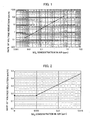
- the inventors have investigated a concentration of SO 2 contained in the fuel-cell air and a decrease in the electromotive force of the fuel cell, and have ascertained that there is a high relationship between them as shown in Example 1 below.
- the inventors have found that the decrease in the electromotive force of the fuel cell caused by the electromotive-force-reducing impurities in fuel-cell air can be substantially completely avoided when the concentration of the sulfur compounds in the fuel-cell air is reduce to 5 ppb or less. Thus, the present invention has been completed.
- the characteristics of the fuel cell can be stably maintained for a long period of time and its lifetime can be extended by controlling the concentration of the sulfur compounds such as SO 2 i.e., the fuel-cell electromotive-force-reducing impurities in air to be supplied to the fuel cell such that a decrease in the electromotive force of the fuel cell is sufficiently prevented.
- the concentration of the sulfur compounds such as SO 2 i.e., the fuel-cell electromotive-force-reducing impurities in air to be supplied to the fuel cell such that a decrease in the electromotive force of the fuel cell is sufficiently prevented.
- the concentration of a sulfur compound in fuel-cell air is reduced to 5 ppb or less by removing sulfur compounds such as SO 2 SO 3 , and H 2 S in air to be supplied to a fuel cell.
- sulfur compounds such as SO 2 SO 3 , and H 2 S in air to be supplied to a fuel cell.
- the concentration of the sulfur compound exceeds 5 ppb, the electromotive force of the fuel cell is promptly decreased due to an electromotive-force-reducing compound in the air.
- the concentration of the sulfur compound in the fuel-cell air may be 5 ppb or less, but, in general, the sulfur compound in the fuel-cell air is preferably removed to a significantly low concentration which is below a detection limit.
- the sulfur compound in the fuel-cell air is preferably removed to 5 ppb or less by using a cleaning filter disclosed in the above-mentioned Japanese Unexamined Patent Application Publication No. 2003-297410 and treating the air at a space velocity of 11100 h -1 or less.
- a cleaning filter suitably used for cleaning the fuel-cell air in the present invention will now be described.
- This cleaning filter includes a three-dimensional reticulate skeleton structure as a filter base and a material retained in this three-dimensional reticulate skeleton structure for decomposing or adsorbing the fuel-cell electromotive-force-reducing impurities.
- the filter base There is not any limitation on the type and shape of the filter base, as long as the material has a three-dimensional structure.
- Polyurethane foam, a three-dimensional net, and a honeycomb structure are preferable.
- polyurethane foam having a three-dimensional reticulate skeleton structure of which a cell membrane is removed by blasting can be suitably used, because the polyurethane foam exhibits low pressure drop and high contact efficiency with air.
- an ether-based material is more preferable than an ester-based material, because the ether-based material is superior in hydrolysis resistance and inhibits the filter base from being deteriorated by hydrolysis due to alkali impregnation described below.
- the number of the cells of the polyurethane foam used as the filter base differs depending on adsorbent particles to be adhered to the base.
- the number of the cells of polyurethane foam is 5 to 50 pores on a line of 25.4 mm length, namely, 5 to 50 pores per inch (PPI). More preferably, the number is about 5 to 20 PPI.
- PPI pores per inch
- the number of the cells is lower than 5 PPI, the pressure drop of the filter is decreased, but the contact efficiency with air is also decreased; which is not preferable.
- the number of the cells is higher than 50 PPI, the contact efficiency with air is increased, but the pressure drop is increased to cause an increase in the load on an air-supplying fan of the fuel-cell system; which is not preferable.
- a material retained in the filter base for adsorbing the fuel-cell electromotive-force-reducing impurities is preferably adsorbent particles.
- the adsorbent particles may be formed of one or more materials.
- the adsorbent particles may be optionally selected and used depending on the purpose of the use thereof from various adsorbent particles formed of, for example, activated charcoal, a zeolite, an ion-exchange resin, activated clay, activated alumina, or powdered silica gel.
- Activated charcoal is generally used because of versatility thereof.
- Charcoal particles having a BET-specific surface of 500 m 2 /g or more, more specifically, about 1000 to 2000 m 2 /g is preferable.
- a larger specific surface is better for adsorbability.
- hardness of the adsorbent is decreased with an increase in the specific surface, and a larger specific surface potentially causes dusting in some types of the adsorbent.
- the activated charcoal may be impregnated with one or more alkaline materials selected from the group consisting of alkaline metal salts, alkaline metal hydroxides, alkaline earth metal salts, and alkaline earth metal hydroxides, for efficiently removing the sulfur compound in atmospheric air which causes a decrease in the electromotive force.
- alkaline materials include potassium carbonate, sodium carbonate, potassium hydroxide, sodium hydroxide, magnesium carbonate, calcium carbonate, magnesium hydroxide, and calcium hydroxide.
- the impregnated charcoal may be prepared by previously impregnating activated charcoal with the alkaline material or may be prepared by retaining activated charcoal in a filter base and then impregnated the charcoal with the alkaline material.
- the activated charcoal is excessively impregnated with the alkaline material, the adsorbing ability of the activated charcoal is impaired. Consequently, the amount of the impregnated alkaline material is preferably lower than 20 wt% of that of the activate charcoal.
- the amount of the impregnated alkaline material is preferably 0.1 to 20 wt%, more preferably 5 to 10 wt% for maintaining the adsorbing ability of the activated charcoal and securing the removing of the sulfur compound.
- the adsorbent particles may support a catalyst for decomposing impurities.
- the catalyst may be directly supported on the filter base not through the adsorbent particles.
- the cleaning filter used in the present invention is preferably prepared by retaining the adsorbent particles in the three-dimensional reticulate skeleton structure of the filter base via a binder layer.
- the cleaning filter is preferably prepared so that a part of the adsorbent particles is in contact with the binder layer and the remaining part is exposed from the binder layer.
- the adsorbent particles exposed from the binder layer become into direct contact with air to highly remove the impurities.
- the binder has strong adhesion to a filter base and barely clogs the pores of the adsorbent particles.
- the binder preferably includes a large amount of a solid component and a small amount of a volatile component, namely, it is suitable that the amount of the solid component is 30 wt% or more, preferably 50 wt% or more, and that the amount of an organic solvent is 50 wt% or less, preferably 0 wt%.
- a solvent-free binder can be suitably used for better adsorbability.
- binder examples include polyether- or polyester-urethane emulsion binders, acrylic emulsion binders, and moisture-curing urethane hot melt binders.
- Urethane prepolymers excessively containing NCO groups more preferably methylene diisocyanate (MDI) urethane prepolymers may be used.
- MDI prepolymers are more preferable than trilene diisocyanate (TDI) prepolymers because, in the MDI prepolymers, free isocyanate is barely generated, the adsorption to the adsorbent particles is low, and hygienic problems in the manufacturing process are small.
- the viscosity of the prepolymer may be too high.
- a minimum amount of an organic solvent is added to the prepolymer and then the application of the prepolymer is performed. After removing almost all of the organic solvent with dried hot air, adsorbent particles are adhered to the prepolymer.
- the adhesion of the solvent can be prevented while facilitating the processability; which is advantageous.
- the binder may be applied to the filter base by impregnating the filter base with the binder in an impregnation tank and then squeezing the excess binder with a roller, or applying the binder to the surface of the filter base by spraying or using a coater and then impregnating the filter base with the binder by using a roller.
- the amount of the binder adhered to the filter base varies depending on the type of the binder, but does not have any specific limitation.
- the amount of the binder is preferably 10 to 100 g/L, more preferably 20 to 50 g/L as an amount of a dried resin per unit volume (apparent volume) of the filter base.
- the amount of the adhered binder is less than 10 g/L, the adhesion retention ability of the adsorbent particles is low. Therefore, difficulty in increasing the amount of the adsorbent particles adhered to the filter base or tendency of detachment of the adsorbent particles from the filter after the processing may occur.
- the amount of the binder exceeds 100 g/L, the pressure drop is increased by the clogging and a broader part of the adsorbent particles is coated with the binder. Therefore, the detachment of the adsorbent particles is inhibited, but the adsorbability of the adsorbent particles themselves is decreased; which is disadvantageous.
- the filter base thus previously adhered with the binder may be provided with the adsorbent particles by fluid bed impregnation, powder spraying, or dropping through a sieve.
- the adsorbent particles When the adsorbent particles are applied to the filter base by the powder spraying or the dropping through a sieve, the adsorbent particles can be uniformly adhered to the filter base by inverting the filter base so as to spray or drop the adsorbent particles to both surfaces of the filter base.
- the impregnation of the adsorbent particles into a three-dimensional reticulate skeleton structure and the certain adhesion of the adsorbent particles to the three-dimensional reticulate skeleton structure can be helped by vibrating the filter base during and/or after the adhesion of the adsorbent particles.
- the adhesion of the adsorbent particles to the three-dimensional reticulate skeleton structure can be helped by slightly compressing the thus-treated three-dimensional reticulate skeleton structure by passing it between a pair of or a plurality pairs of rollers after the adhesion of the adsorbent particles.
- the distance between the pair of rollers is preferable 90 to 60% of the thickness of the three-dimensional reticulate skeleton structure of the filter base.
- the binder is cured.
- the curing of the binder may be performed by a method suitable for the respective binders.
- the binder can be cured by superheated vapor. The process of this method is simple and a high fixing strength can be achieved.
- the adsorbent particles are partially coated with the binder, fine pores are formed in the coat by the generation of carbon dioxide when the urethane is cured. Consequently, a decrease in the adsorbability is small.
- an additional binder may be further applied on the former binder and then these binders may be cured. This significantly strongly retains the adsorbent particles in the three-dimensional reticulate skeleton structure of the filter base.
- the entire surfaces of the adsorbent particles fixed to the surficial layer are coated with the binder. Consequently, the fixing strength to the three-dimensional reticulate skeleton structure is increased, but the adsorbability of the adsorbent particles at that surficial layer portion is decreased. However, since the most part of the adsorbent particles fixed in the layer of the three-dimensional reticulate skeleton structure does not receive an influence of the binder that is applied to the surficial layer of the three-dimensional reticulate skeleton structure, the adsorbability of the entire adsorbent is not so decreased.
- the thickness of the applied surficial layer can be controlled by adjusting the amount of the binder and may be optionally determined in consideration of an increase in the fixing strength of the adsorbent particles in the surficial layer and a decrease in the adsorbability of the entire adsorbent.
- the ratio of an adsorbability reduction due to the application of the surficial layer is decreased with an increase in the thickness of the three-dimensional reticulate skeleton structure.
- the binder applied to the surficial layer may be the same as that previously applied to the entire three-dimensional reticulate skeleton structure.
- an effect of a combination of binders may be obtained by using a plastic binder as the previous binder applied to the entire structure so that the flexibility of the three-dimensional reticulate skeleton structure is not impaired and a hard binder as the binder applied to the surficial layer so that a high fixing strength is achieved.
- a plastic binder as the previous binder applied to the entire structure so that the flexibility of the three-dimensional reticulate skeleton structure is not impaired
- a hard binder as the binder applied to the surficial layer so that a high fixing strength is achieved.
- the use of an emulsion binder which readily causes occurrence of a defect such as pinholes in the coat, is also advantageous from the viewpoint of air permeability.
- air to be supplied to a fuel cell for introducing oxygen to a cathode passes through such a cleaning filter to remove the fuel-cell electromotive-force-reducing impurities in the air.
- the space velocity of this air is preferably 11100 h -1 or less.
- the cleaning filter promptly reaches breakthrough (namely, the ability for removing the fuel-cell electromotive-force-reducing impurities is impaired), and the fuel-cell electromotive-force-reducing impurities cannot be stably and certainly removed.
- a lower space velocity is better for maintaining the performance of removing the fuel-cell electromotive-force-reducing impurities, but the excessively low space velocity causes a decrease in the processing efficiency.
- the space velocity is preferably 10000 h -1 or less, more preferably 7000 to 8000 h -1 .
- the cleaning of the fuel-cell air is preferably conducted according to an ordinary method except that the amount of the cleaning filter and the velocity of the air flow are controlled so as to obtain such a space velocity.
- air containing the sulfur compound at a concentration of 5 ppb or less is obtained and supplied to a fuel cell.
- a dust-removing filter may be provided upstream of the cleaning filter. Fuel-cell air may be supplied to this dust-removing filter to previously remove dust and then supplied to the cleaning filter to clean the air. In such a case, the performance of the cleaning filter can be further maintained over a long period of time.
- the dust-removing filter may be provided downstream of the cleaning filter so as to trap the adsorbent particles detached from the cleaning filter by supplying fuel-cell air cleaned by the cleaning filter to the dust-removing filter. In this case, an inflow of the adsorbent particles detached from the cleaning filter into a fuel cell can be certainly prevented.
- the dust-removing filter examples include charged non-woven fabric, spunpond non-woven fabric, melt blue non-woven fabric, needle-punched non-woven fabric, embossed non-woven fabric, HEPA filters, and ULPA filters. Any material can be used for the filter without specific limitation. Examples of the material include organic fabric such as polypropylenes, polyesters, and polyimides; and inorganic fabric such as boron fiber and glass fiber. Furthermore, the dust-removing filter can be used in various shapes, such as a pleat, honeycomb, or flat-shape. Regarding the weight, there is not any specific limitation. The weight is preferably 15 to 500 g/m 2 , more preferably 50 to 200 g/m 2 from the viewpoints of the dust-removing performance and flow resistance.
- the fuel cell may be an installation type or a movable type for mounting to a vehicle.
- the anode and cathode of the unit cell of the polymer electrolyte fuel cell having the above-mentioned constitution were supplied with hydrogen humidified to 100% relative humidity and air humidified to 90% relative humidity, respectively.
- the reaction-gas flow was adjusted to a hydrogen utilization ratio of 70% and an oxygen utilization ratio of 40% at a cell temperature of 80°C at a current density of 350 mA/cm 2 .
- the examination of the voltage-reduction rate of the fuel cell was started right after the addition of SO 2 to the cathode air.
- the SO 2 concentration in the air to be supplied to the cathode was defined as a volume concentration of dried SO 2 (at normal temperatures and pressures) after excluding moisture at a cathode-air inlet, and was adjusted to 5 ppm, 1 ppm, 0.1 ppm, 0.04 ppm (40 ppb), and 0.005 ppm (5 ppb).
- FIGS. 1 and 2 show a relationship between a concentration of SO 2 in air to be supplied to a cathode and a rate of voltage reduction.
- the rate of the voltage reduction (0.17 mV/h) is the same value as that in the air not containing SO 2 .
- the rate of the voltage reduction in the air not containing SO 2 means a rate of the voltage reduction caused by a factor deteriorating the catalyst activity, i.e., an electromotive-force-reducing factor which is irrelevant to the electromotive-force-reducing impurities in the cathode air. It is obvious from the result of this experiment that the voltage reduction caused by the electromotive-force-reducing impurities in the air can be substantially completely prevented by reducing the SO 2 concentration in the air to 5 ppb or less.
- Polyether-polyurethane foam having cells removed membranes thereof at 10 PPI (the foam: 250 mm ⁇ 250 mm ⁇ 5 mm (thickness), Tradename: Everlight SF, Product Number: QW-09 5t, manufactured by Bridgestone Corporation) was used as a filter base.
- This foam was impregnated with a polyether urethane emulsion binder containing 50 wt% of a solid component so that the amount of the adhered binder per unit volume of the filter base was 30 g/L as a dried resin.
- coconut-shell activated charcoal having an average particle size of 30 mesh (BET specific surface area: 1500 m 2 /g) was uniformly supplied and adhered to both surfaces of and further into the base by dropping through a sieve. The amount of the activated charcoal was controlled to 150 g/L per unit volume of the filter base.
- a solution containing 13.8 wt% of potassium carbonate was applied to both surfaces of the filter base adhered with the activated charcoal so that the amount of the adhered solution is 326 g/m 2 (adhesion amount of potassium carbonate: 45 m 2 /g, adhesion ratio of the potassium carbonate to the activated charcoal: 6 wt%). Then, the filter base was sufficiently dried to obtain a cleaning filter material.
- the cleaning filter materials prepared in Manufacturing example 1 each having a thickness of 5 mm were stacked at the number of sheets shown in Table 1 to obtain three types of cleaning filter Nos. 1, 2, and 3 having the total thicknesses shown in Table 1.
- the SO 2 gas adsorption test and the pressure drop measurement below were carried out.
- the cleaning filter No. 2 was cut so as to have a diameter of 20 mm ⁇ .
- the cut cleaning filter is disposed in a vertical column 1 (a glass column having an internal diameter of 20 mm ⁇ and a length of 200 mm) shown in FIG. 4 at a substantially center portion in the height direction of the column so that the thickness direction of the filter is the height direction of the column.
- SO 2 gas (50 ppm) and N 2 gas are supplied to a gas mixer 5 having a flow meter from a SO 2 tank 3 and a N 2 tank 4, respectively.
- the SO 2 gas is diluted 100 times to 500 ppb in the gas mixer 5 as SO 2 -N 2 gas.
- the resulting gas is introduced to the column 1 from the bottom thereof at a gas flow of 2.333 L/min.
- the reference numerals 6 and 7 represent three-way valves, and inlet gas and outlet gas are sampled to sequentially measure the respective SO 2 concentrations by a SO 2 gas measuring device (not shown, a device for an ultraviolet fluorescence method having a detection limit of 0.1 ppb).
- the linear velocity is a value obtained by dividing a gas-flow quantity by a filter area.
- FIG. 3 shows changes of SO 2 concentration in the outlet gas according to the time.
- the SO 2 concentration in atmospheric air is about 5 ppb, which is about 1/100 of the SO 2 concentration 500 ppb used in the adsorption test. Consequently, it is estimated that the usable life of the cleaning filter will be 100 times longer than the breakthrough time in this adsorption test when the filter is used for cleaning the air to be supplied to a practical fuel cell. Therefore, the 100-fold of the breakthrough time is also shown in Table 1 as an estimated usable life in practical use.
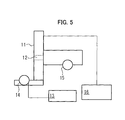
- the cleaning filter material 12 (one sheet having a thickness of 5 mm) prepared in Manufacturing example 1 was disposed in a vertical wind-tunnel 11 (made of SUS having an internal diameter of 250 mm ⁇ 250 mm) at a substantially central portion in the height direction of the wind-tunnel so that the thickness direction of the filter was in the height direction of the wind-tunnel.
- An air-supplying fan 14 sent air to the wind-tunnel 11 from the bottom. The number of revolution of the fan was controlled by an inverter 13 so that the air velocity measured by a wind gauge 16 was 1 m/sec, 2 m/sec, or 3 m/sec.
- the linear velocity was 0.12 m/sec when one sheet of the cleaning filter material was used in the SO 2 gas adsorption test.
- Pressure drop was calculated by substituting the linear velocity of 0.12 m/sec into the above-mentioned equation. The resulting value of this pressure drop was multiplied by the number of stacked sheets of each filter to calculate the pressure drop of each filter. The result is shown in Table 1 (without dust-removing filter).
- each of the dust-removing filters was composed of two sheets of charged non-woven fabric each having a weight of 50 g/m 2 , and four sheets in total were used for each measurement. The result is shown in Table 1 (with dust-removing filter).
- a fuel-cell system used in the test included a reformulation unit, a fuel-cell body, an electric control unit, and accessories.
- Reformulated gas obtained by reformulating town gas (13A) as raw fuel gas by the reformulation unit was supplied to an anode of the fuel-cell body.
- Air passed through the cleaning filter No. 1 prepared in Experimental example 2 and cut into 100 mm ⁇ was supplied to a cathode. Under the conditions of a DC generating-end output of 0.95 kW and an average air flow of 3.5 Nm 3 /h, electric-power generation was continuously performed for more than 1000 hr.
- Dust-removing filters (each composed of stacked 2 sheets of charged polypropylene non-woven fabric having a weight of 50 g/m 2 ) were disposed upstream and downstream of the cleaning filter to clean the introduced air and the cleaned air.
- the average SO x concentration and average NO x concentration in atmospheric air were 18 ppb and 50 ppb, respectively.
- the SO x in atmospheric air was certainly removed to the detection limit or less by the cleaning filter during the continuous operation of the electric-power generation.
- Electric-power generation was continuously operated as in Example 1 except that the air to be supplied to the cathode was not cleaned with the cleaning filter. The ratio of electromotive-force reduction was examined.
- Example 1 Comparative example 1 Cleaning filter Presence Absence Space velocity (h -1 ) 5570 - Ratio of electromotive-force reduction (%) 54 100
Landscapes
- Chemical & Material Sciences (AREA)
- Engineering & Computer Science (AREA)
- General Chemical & Material Sciences (AREA)
- Chemical Kinetics & Catalysis (AREA)
- Sustainable Energy (AREA)
- Life Sciences & Earth Sciences (AREA)
- Sustainable Development (AREA)
- Electrochemistry (AREA)
- Manufacturing & Machinery (AREA)
- Analytical Chemistry (AREA)
- Oil, Petroleum & Natural Gas (AREA)
- Fuel Cell (AREA)
- Catalysts (AREA)
- Solid-Sorbent Or Filter-Aiding Compositions (AREA)
- Separation Of Gases By Adsorption (AREA)
- Filtering Materials (AREA)
Applications Claiming Priority (2)
| Application Number | Priority Date | Filing Date | Title |
|---|---|---|---|
| JP2003427216 | 2003-12-24 | ||
| PCT/JP2004/018996 WO2005062411A1 (fr) | 2003-12-24 | 2004-12-20 | Procede et appareil permettant de purifier l'air destine a une pile a combustible et pile a combustible |
Publications (3)
| Publication Number | Publication Date |
|---|---|
| EP1699103A1 true EP1699103A1 (fr) | 2006-09-06 |
| EP1699103A4 EP1699103A4 (fr) | 2011-06-15 |
| EP1699103B1 EP1699103B1 (fr) | 2015-09-30 |
Family
ID=34708885
Family Applications (1)
| Application Number | Title | Priority Date | Filing Date |
|---|---|---|---|
| EP04807353.0A Expired - Lifetime EP1699103B1 (fr) | 2003-12-24 | 2004-12-20 | Procede et appareil permettant de purifier l'air destine a une pile a combustible et pile a combustible |
Country Status (6)
| Country | Link |
|---|---|
| US (2) | US20060240295A1 (fr) |
| EP (1) | EP1699103B1 (fr) |
| JP (1) | JP4956996B2 (fr) |
| CN (1) | CN100541897C (fr) |
| CA (1) | CA2550875C (fr) |
| WO (1) | WO2005062411A1 (fr) |
Cited By (3)
| Publication number | Priority date | Publication date | Assignee | Title |
|---|---|---|---|---|
| WO2008035175A1 (fr) * | 2006-09-20 | 2008-03-27 | Nissan Motor Co., Ltd. | Système de pile à combustible |
| WO2011036356A1 (fr) * | 2009-09-25 | 2011-03-31 | Commissariat à l'Energie Atomique et aux Energies Alternatives | Procédé d'alimentation à partir d'une pile à combustible tenant compte de la pollution par l'oxyde de soufre et dispositif d'alimentation |
| DE102012221430A1 (de) | 2011-11-30 | 2013-06-06 | Robert Bosch Gmbh | Brennstoffzellensystem |
Families Citing this family (18)
| Publication number | Priority date | Publication date | Assignee | Title |
|---|---|---|---|---|
| TW200743248A (en) | 2006-05-05 | 2007-11-16 | Asia Pacific Fuel Cell Tech | Fuel cell system incorporating humidifying apparatus into un-reacted gas outlet piping of fuel cell |
| CN101079484B (zh) * | 2006-05-23 | 2011-01-19 | 亚太燃料电池科技股份有限公司 | 结合加湿装置于未反应气体排放管路的燃料电池系统 |
| JP2008257891A (ja) * | 2007-03-30 | 2008-10-23 | Equos Research Co Ltd | 燃料電池システム |
| JP5328110B2 (ja) * | 2007-05-18 | 2013-10-30 | 日本エンバイロケミカルズ株式会社 | 円筒形活性炭フィルター |
| CN101306296B (zh) * | 2008-07-14 | 2011-06-22 | 新源动力股份有限公司 | 一种消除燃料电池氧化剂中二氧化硫的方法 |
| US20100273068A1 (en) * | 2009-04-22 | 2010-10-28 | Adaptive Materials, Inc. | Fuel cell system including a fuel filter member with a filter property indicator |
| US20110189587A1 (en) * | 2010-02-01 | 2011-08-04 | Adaptive Materials, Inc. | Interconnect Member for Fuel Cell |
| JP5853675B2 (ja) * | 2011-12-26 | 2016-02-09 | 株式会社ブリヂストン | 燃料電池用フィルター |
| JP2014147903A (ja) * | 2013-02-01 | 2014-08-21 | Sumitomo Bakelite Co Ltd | 基材担持触媒および基材担持触媒の製造方法 |
| JP6534653B2 (ja) * | 2014-05-01 | 2019-06-26 | 三喜ゴム株式会社 | 燃料電池用フィルター |
| JP6210229B2 (ja) * | 2014-11-26 | 2017-10-11 | トヨタ自動車株式会社 | 燃料電池の製造方法 |
| KR20170098511A (ko) * | 2016-02-22 | 2017-08-30 | 현대자동차주식회사 | 연료전지 자동차용 에어 필터 |
| JP7405507B2 (ja) * | 2019-01-09 | 2023-12-26 | イビデン株式会社 | 硫黄系ガス吸着構造体及び組電池 |
| CN111082099B (zh) * | 2019-12-05 | 2023-02-28 | 同济大学 | 一种可调节温度的燃料电池发动机空气子系统 |
| CN114695922B (zh) * | 2021-12-14 | 2022-11-18 | 中氢新能(北京)新能源技术研究院有限公司 | 一种甲醇燃料电池的气液分离器 |
| US12458913B2 (en) | 2022-04-19 | 2025-11-04 | Cummins Inc. | Multi-stage filtration system for fuel cell hybrid propulsion system |
| CN115663241B (zh) * | 2022-12-14 | 2023-03-10 | 佛山市清极能源科技有限公司 | 一种燃料电池电堆寿命的监测方法 |
| CN119481087B (zh) * | 2025-01-15 | 2025-05-06 | 中国科学院大连化学物理研究所 | 一种质子交换膜燃料电池阴极及包括其的膜电极 |
Family Cites Families (23)
| Publication number | Priority date | Publication date | Assignee | Title |
|---|---|---|---|---|
| US1781664A (en) * | 1926-07-02 | 1930-11-11 | Paul O Rockwell | Process and apparatus for purifying air |
| GB1154008A (en) * | 1966-11-28 | 1969-06-04 | Shell Int Research | Process for the Removal of Suplhur Oxides from Gas Mixtures and an apparatus therefor |
| US3920587A (en) * | 1972-08-11 | 1975-11-18 | Union Carbide Corp | Open-cell rigid polyether polyurethane foam |
| JP3253988B2 (ja) * | 1991-10-22 | 2002-02-04 | 保土谷化学工業株式会社 | ポリオレフィン樹脂素材用水性接着剤 |
| US5213912A (en) * | 1991-12-30 | 1993-05-25 | International Fuel Cells Corporation | Molten carbonate fuel cell sulfur scrubber |
| US5492684A (en) * | 1993-07-06 | 1996-02-20 | Mobil Oil Corporation | Graded-bed system for improved separations |
| SE501971C2 (sv) * | 1993-11-10 | 1995-07-03 | Mimat Ab | Användning av hydrofob zeolit för rening av luft som innehåller merkaptaner och H2S |
| GB9511505D0 (en) * | 1995-06-07 | 1995-08-02 | Kuester Stephen M | Personal protection |
| JP3530413B2 (ja) | 1999-03-25 | 2004-05-24 | 三洋電機株式会社 | 燃料電池発電システム及びその運転方法 |
| JP2000300687A (ja) * | 1999-04-20 | 2000-10-31 | Takuma Co Ltd | ダイオキシンとその類縁化合物除去用保護具及びダイオキシンとその類縁化合物の除去方法 |
| JP2000327305A (ja) | 1999-05-12 | 2000-11-28 | Sanyo Electric Co Ltd | Co除去器及び燃料電池発電システム |
| JP2001313057A (ja) | 2000-04-27 | 2001-11-09 | Asahi Glass Co Ltd | 固体高分子型燃料電池用イオン交換性フィルタの製造方法 |
| JP2002093452A (ja) | 2000-09-11 | 2002-03-29 | Ishikawajima Harima Heavy Ind Co Ltd | 燃料電池発電設備の不純物ガス除去方法及びその不純物ガス除去装置 |
| US6432177B1 (en) * | 2000-09-12 | 2002-08-13 | Donaldson Company, Inc. | Air filter assembly for low temperature catalytic processes |
| JP2002103506A (ja) * | 2000-09-26 | 2002-04-09 | Matsushita Electric Works Ltd | 化粧基材及びその分離方法 |
| JP2003001028A (ja) * | 2001-06-22 | 2003-01-07 | Bridgestone Corp | フィルター材 |
| US6951697B2 (en) * | 2001-09-11 | 2005-10-04 | Donaldson Company, Inc. | Integrated systems for use with fuel cells, and methods |
| JP4352652B2 (ja) * | 2002-04-05 | 2009-10-28 | 株式会社ブリヂストン | 燃料電池の流体浄化器 |
| US20040023096A1 (en) * | 2002-07-31 | 2004-02-05 | Pratt Steven Duane | Fuel cell system having a filter element for purifying ambient environmental air |
| US20040118747A1 (en) * | 2002-12-18 | 2004-06-24 | Cutler Willard A. | Structured adsorbents for desulfurizing fuels |
| JP2004327429A (ja) * | 2003-04-11 | 2004-11-18 | Matsushita Electric Ind Co Ltd | 燃料電池および燃料電池用空気浄化装置 |
| EP1469544A1 (fr) * | 2003-04-11 | 2004-10-20 | Matsushita Electric Industrial Co., Ltd. | Procédé de fonctionnement d'une pile à combustible, dispositif de purification del'air, et pile à combustible |
| US6979505B2 (en) * | 2003-06-09 | 2005-12-27 | Utc Fuel Cells, Llc | Method and apparatus for removal of contaminants from a hydrogen processor feed stream, as in a fuel cell power plant |
-
2004
- 2004-12-20 JP JP2005516483A patent/JP4956996B2/ja not_active Expired - Lifetime
- 2004-12-20 CN CNB2004800387521A patent/CN100541897C/zh not_active Expired - Lifetime
- 2004-12-20 CA CA2550875A patent/CA2550875C/fr not_active Expired - Lifetime
- 2004-12-20 WO PCT/JP2004/018996 patent/WO2005062411A1/fr not_active Ceased
- 2004-12-20 EP EP04807353.0A patent/EP1699103B1/fr not_active Expired - Lifetime
-
2006
- 2006-06-22 US US11/472,385 patent/US20060240295A1/en not_active Abandoned
-
2009
- 2009-07-29 US US12/511,572 patent/US20100003555A1/en not_active Abandoned
Cited By (5)
| Publication number | Priority date | Publication date | Assignee | Title |
|---|---|---|---|---|
| WO2008035175A1 (fr) * | 2006-09-20 | 2008-03-27 | Nissan Motor Co., Ltd. | Système de pile à combustible |
| US8067124B2 (en) | 2006-09-20 | 2011-11-29 | Nissan Motor Co., Ltd. | Fuel cell system |
| WO2011036356A1 (fr) * | 2009-09-25 | 2011-03-31 | Commissariat à l'Energie Atomique et aux Energies Alternatives | Procédé d'alimentation à partir d'une pile à combustible tenant compte de la pollution par l'oxyde de soufre et dispositif d'alimentation |
| FR2950739A1 (fr) * | 2009-09-25 | 2011-04-01 | Commissariat Energie Atomique | Procede d'alimentation a partir d'une pile a combustible tenant compte de la pollution par l'oxyde de soufre et dispositif d'alimentation |
| DE102012221430A1 (de) | 2011-11-30 | 2013-06-06 | Robert Bosch Gmbh | Brennstoffzellensystem |
Also Published As
| Publication number | Publication date |
|---|---|
| CN1898832A (zh) | 2007-01-17 |
| EP1699103A4 (fr) | 2011-06-15 |
| US20100003555A1 (en) | 2010-01-07 |
| CA2550875C (fr) | 2011-04-19 |
| CN100541897C (zh) | 2009-09-16 |
| EP1699103B1 (fr) | 2015-09-30 |
| JPWO2005062411A1 (ja) | 2007-07-19 |
| WO2005062411A1 (fr) | 2005-07-07 |
| JP4956996B2 (ja) | 2012-06-20 |
| US20060240295A1 (en) | 2006-10-26 |
| CA2550875A1 (fr) | 2005-07-07 |
Similar Documents
| Publication | Publication Date | Title |
|---|---|---|
| US20100003555A1 (en) | Method and device for decontamination air for fuel cell, and fuel cell | |
| RU2447936C1 (ru) | Катализатор на углеродной основе для десульфуризации дымовых газов, и способ его получения, и его использование для удаления ртути в дымовых газах | |
| EP2257358B1 (fr) | Produits d'addition d'amines et d'acides polycarboxyliques, et milieux filtrants comprenant de tels produits d'addition | |
| EP3045224B1 (fr) | Adsorbant de gaz, feuille d'adsorption de gaz et filtre à air | |
| US20090233155A1 (en) | Using ionic liquids | |
| EP3266838A1 (fr) | Composition pour revêtement de photocatalyseur actif en lumière visible, et filtre de purification d'air | |
| WO2007142641A1 (fr) | Système catalyseur de monoxyde de carbone amélioré pour élimination de co | |
| CN112870931A (zh) | 电化学法降解气态有机污染物的装置及其方法 | |
| CN113423485A (zh) | 用于沉积氮氧化物的过滤介质 | |
| KR102221361B1 (ko) | 공기정화 필터 | |
| JP4352652B2 (ja) | 燃料電池の流体浄化器 | |
| JP2002119809A (ja) | フィルタ、並びにそれを用いた空気清浄機及びエアーコンディショナー | |
| JP6534653B2 (ja) | 燃料電池用フィルター | |
| US8758713B2 (en) | Method for photooxidation of carbon monoxide in gas phase to carbon dioxide | |
| EP4410418A1 (fr) | Adsorbant de gaz et feuille d'adsorption de gaz, milieu filtrant et filtre à air l'utilisant | |
| JPH07116510A (ja) | 吸着体及び多孔吸着材 | |
| US20050095468A1 (en) | Fluid cleaner and fuel-cell generator | |
| CN104010699B (zh) | 空气处理用设备 | |
| CA2050260C (fr) | Procede electrochimique et appareil servant a reduire la teneur en oxydants de l'air a l'interieur de l'habitacle d'une automobile | |
| CN118320610A (zh) | 空气净化材料及其制备方法、空气净化设备 | |
| JP2013134860A (ja) | 燃料電池用フィルター | |
| EP4238645A1 (fr) | Agent adhésif, son procédé de fabrication, matériau de filtration et filtre à air | |
| KR20050000018A (ko) | 전극적층반응기를 이용한 공기정화장치 |
Legal Events
| Date | Code | Title | Description |
|---|---|---|---|
| PUAI | Public reference made under article 153(3) epc to a published international application that has entered the european phase |
Free format text: ORIGINAL CODE: 0009012 |
|
| 17P | Request for examination filed |
Effective date: 20060622 |
|
| AK | Designated contracting states |
Kind code of ref document: A1 Designated state(s): DE FR |
|
| DAX | Request for extension of the european patent (deleted) | ||
| RBV | Designated contracting states (corrected) |
Designated state(s): DE FR |
|
| A4 | Supplementary search report drawn up and despatched |
Effective date: 20110512 |
|
| 17Q | First examination report despatched |
Effective date: 20120712 |
|
| GRAP | Despatch of communication of intention to grant a patent |
Free format text: ORIGINAL CODE: EPIDOSNIGR1 |
|
| INTG | Intention to grant announced |
Effective date: 20150507 |
|
| RIN1 | Information on inventor provided before grant (corrected) |
Inventor name: AOKI, TSUTOMU Inventor name: KUWABARA, TADASHI, YOKOHAMA PLANT, BRIDGESTONE COR Inventor name: MORI, HISASHI, YOKOHAMA PLANT, BRIDGESTONE CORP. Inventor name: CHIZAWA, HIROSHI Inventor name: SHIGYO, YASUSHIGE, YOKOHAMA PLANT, BRIDGESTONE COR |
|
| GRAS | Grant fee paid |
Free format text: ORIGINAL CODE: EPIDOSNIGR3 |
|
| GRAA | (expected) grant |
Free format text: ORIGINAL CODE: 0009210 |
|
| AK | Designated contracting states |
Kind code of ref document: B1 Designated state(s): DE FR |
|
| REG | Reference to a national code |
Ref country code: DE Ref legal event code: R096 Ref document number: 602004047998 Country of ref document: DE |
|
| REG | Reference to a national code |
Ref country code: FR Ref legal event code: PLFP Year of fee payment: 12 |
|
| REG | Reference to a national code |
Ref country code: DE Ref legal event code: R097 Ref document number: 602004047998 Country of ref document: DE |
|
| PLBE | No opposition filed within time limit |
Free format text: ORIGINAL CODE: 0009261 |
|
| STAA | Information on the status of an ep patent application or granted ep patent |
Free format text: STATUS: NO OPPOSITION FILED WITHIN TIME LIMIT |
|
| 26N | No opposition filed |
Effective date: 20160701 |
|
| REG | Reference to a national code |
Ref country code: FR Ref legal event code: PLFP Year of fee payment: 13 |
|
| REG | Reference to a national code |
Ref country code: FR Ref legal event code: PLFP Year of fee payment: 14 |
|
| REG | Reference to a national code |
Ref country code: DE Ref legal event code: R081 Ref document number: 602004047998 Country of ref document: DE Owner name: TOSHIBA ENERGY SYSTEMS & SOLUTIONS CORPORATION, JP Free format text: FORMER OWNERS: BRIDGESTONE CORP., TOKYO, JP; TOSHIBA FUEL CELL POWER SYSTEMS CORP., TOKYO, JP Ref country code: DE Ref legal event code: R082 Ref document number: 602004047998 Country of ref document: DE Representative=s name: HOFFMANN - EITLE PATENT- UND RECHTSANWAELTE PA, DE Ref country code: DE Ref legal event code: R081 Ref document number: 602004047998 Country of ref document: DE Owner name: SANKI RUBBER CO., LTD., OSAKA-SHI, JP Free format text: FORMER OWNERS: BRIDGESTONE CORP., TOKYO, JP; TOSHIBA FUEL CELL POWER SYSTEMS CORP., TOKYO, JP Ref country code: DE Ref legal event code: R081 Ref document number: 602004047998 Country of ref document: DE Owner name: TOSHIBA FUEL CELL POWER SYSTEMS CORP., JP Free format text: FORMER OWNERS: BRIDGESTONE CORP., TOKYO, JP; TOSHIBA FUEL CELL POWER SYSTEMS CORP., TOKYO, JP |
|
| REG | Reference to a national code |
Ref country code: DE Ref legal event code: R082 Ref document number: 602004047998 Country of ref document: DE Representative=s name: HOFFMANN - EITLE PATENT- UND RECHTSANWAELTE PA, DE Ref country code: DE Ref legal event code: R081 Ref document number: 602004047998 Country of ref document: DE Owner name: SANKI RUBBER CO., LTD., OSAKA-SHI, JP Free format text: FORMER OWNERS: SANKI RUBBER CO., LTD., OSAKA-SHI, OSAKA, JP; TOSHIBA FUEL CELL POWER SYSTEMS CORP., TOKYO, JP Ref country code: DE Ref legal event code: R081 Ref document number: 602004047998 Country of ref document: DE Owner name: TOSHIBA ENERGY SYSTEMS & SOLUTIONS CORPORATION, JP Free format text: FORMER OWNERS: SANKI RUBBER CO., LTD., OSAKA-SHI, OSAKA, JP; TOSHIBA FUEL CELL POWER SYSTEMS CORP., TOKYO, JP |
|
| PGFP | Annual fee paid to national office [announced via postgrant information from national office to epo] |
Ref country code: FR Payment date: 20231221 Year of fee payment: 20 Ref country code: DE Payment date: 20231214 Year of fee payment: 20 |
|
| REG | Reference to a national code |
Ref country code: DE Ref legal event code: R071 Ref document number: 602004047998 Country of ref document: DE |