EP1699390B1 - Instrument d'insertion pour implant - Google Patents
Instrument d'insertion pour implant Download PDFInfo
- Publication number
- EP1699390B1 EP1699390B1 EP04815252.4A EP04815252A EP1699390B1 EP 1699390 B1 EP1699390 B1 EP 1699390B1 EP 04815252 A EP04815252 A EP 04815252A EP 1699390 B1 EP1699390 B1 EP 1699390B1
- Authority
- EP
- European Patent Office
- Prior art keywords
- implant
- grabber
- pair
- slots
- outer sleeve
- Prior art date
- Legal status (The legal status is an assumption and is not a legal conclusion. Google has not performed a legal analysis and makes no representation as to the accuracy of the status listed.)
- Expired - Lifetime
Links
- 239000007943 implant Substances 0.000 title claims description 131
- 238000002513 implantation Methods 0.000 claims description 22
- 238000003780 insertion Methods 0.000 claims description 21
- 230000037431 insertion Effects 0.000 claims description 20
- 230000007246 mechanism Effects 0.000 claims description 20
- 238000004513 sizing Methods 0.000 claims description 4
- 238000000034 method Methods 0.000 description 12
- 230000004927 fusion Effects 0.000 description 9
- 230000006835 compression Effects 0.000 description 4
- 238000007906 compression Methods 0.000 description 4
- 230000001045 lordotic effect Effects 0.000 description 4
- 230000006378 damage Effects 0.000 description 3
- 239000000463 material Substances 0.000 description 3
- 238000004806 packaging method and process Methods 0.000 description 3
- 230000008569 process Effects 0.000 description 3
- 239000000523 sample Substances 0.000 description 3
- 230000001954 sterilising effect Effects 0.000 description 3
- 238000004659 sterilization and disinfection Methods 0.000 description 3
- 238000001356 surgical procedure Methods 0.000 description 3
- 208000027418 Wounds and injury Diseases 0.000 description 2
- 210000000988 bone and bone Anatomy 0.000 description 2
- 208000014674 injury Diseases 0.000 description 2
- 239000004033 plastic Substances 0.000 description 2
- 229920003023 plastic Polymers 0.000 description 2
- 230000000717 retained effect Effects 0.000 description 2
- 229920000049 Carbon (fiber) Polymers 0.000 description 1
- 239000004677 Nylon Substances 0.000 description 1
- -1 Peek Substances 0.000 description 1
- 229920003295 Radel® Polymers 0.000 description 1
- 239000004676 acrylonitrile butadiene styrene Substances 0.000 description 1
- 239000004917 carbon fiber Substances 0.000 description 1
- 230000008878 coupling Effects 0.000 description 1
- 238000010168 coupling process Methods 0.000 description 1
- 238000005859 coupling reaction Methods 0.000 description 1
- 230000000881 depressing effect Effects 0.000 description 1
- 238000005516 engineering process Methods 0.000 description 1
- 238000002347 injection Methods 0.000 description 1
- 239000007924 injection Substances 0.000 description 1
- 230000008376 long-term health Effects 0.000 description 1
- 230000014759 maintenance of location Effects 0.000 description 1
- 238000004519 manufacturing process Methods 0.000 description 1
- 230000013011 mating Effects 0.000 description 1
- VNWKTOKETHGBQD-UHFFFAOYSA-N methane Chemical compound C VNWKTOKETHGBQD-UHFFFAOYSA-N 0.000 description 1
- 229920001778 nylon Polymers 0.000 description 1
- 230000001144 postural effect Effects 0.000 description 1
- 238000002360 preparation method Methods 0.000 description 1
- 125000006850 spacer group Chemical group 0.000 description 1
- 210000001519 tissue Anatomy 0.000 description 1
- 230000007704 transition Effects 0.000 description 1
- 230000002792 vascular Effects 0.000 description 1
Images







Classifications
-
- A—HUMAN NECESSITIES
- A61—MEDICAL OR VETERINARY SCIENCE; HYGIENE
- A61F—FILTERS IMPLANTABLE INTO BLOOD VESSELS; PROSTHESES; DEVICES PROVIDING PATENCY TO, OR PREVENTING COLLAPSING OF, TUBULAR STRUCTURES OF THE BODY, e.g. STENTS; ORTHOPAEDIC, NURSING OR CONTRACEPTIVE DEVICES; FOMENTATION; TREATMENT OR PROTECTION OF EYES OR EARS; BANDAGES, DRESSINGS OR ABSORBENT PADS; FIRST-AID KITS
- A61F2/00—Filters implantable into blood vessels; Prostheses, i.e. artificial substitutes or replacements for parts of the body; Appliances for connecting them with the body; Devices providing patency to, or preventing collapsing of, tubular structures of the body, e.g. stents
- A61F2/02—Prostheses implantable into the body
- A61F2/30—Joints
- A61F2/46—Special tools for implanting artificial joints
-
- A—HUMAN NECESSITIES
- A61—MEDICAL OR VETERINARY SCIENCE; HYGIENE
- A61F—FILTERS IMPLANTABLE INTO BLOOD VESSELS; PROSTHESES; DEVICES PROVIDING PATENCY TO, OR PREVENTING COLLAPSING OF, TUBULAR STRUCTURES OF THE BODY, e.g. STENTS; ORTHOPAEDIC, NURSING OR CONTRACEPTIVE DEVICES; FOMENTATION; TREATMENT OR PROTECTION OF EYES OR EARS; BANDAGES, DRESSINGS OR ABSORBENT PADS; FIRST-AID KITS
- A61F2/00—Filters implantable into blood vessels; Prostheses, i.e. artificial substitutes or replacements for parts of the body; Appliances for connecting them with the body; Devices providing patency to, or preventing collapsing of, tubular structures of the body, e.g. stents
- A61F2/02—Prostheses implantable into the body
- A61F2/30—Joints
- A61F2/46—Special tools for implanting artificial joints
- A61F2/4603—Special tools for implanting artificial joints for insertion or extraction of endoprosthetic joints or of accessories thereof
- A61F2/4611—Special tools for implanting artificial joints for insertion or extraction of endoprosthetic joints or of accessories thereof of spinal prostheses
-
- A—HUMAN NECESSITIES
- A61—MEDICAL OR VETERINARY SCIENCE; HYGIENE
- A61B—DIAGNOSIS; SURGERY; IDENTIFICATION
- A61B90/00—Instruments, implements or accessories specially adapted for surgery or diagnosis and not covered by any of the groups A61B1/00 - A61B50/00, e.g. for luxation treatment or for protecting wound edges
- A61B90/03—Automatic limiting or abutting means, e.g. for safety
- A61B2090/033—Abutting means, stops, e.g. abutting on tissue or skin
-
- A—HUMAN NECESSITIES
- A61—MEDICAL OR VETERINARY SCIENCE; HYGIENE
- A61B—DIAGNOSIS; SURGERY; IDENTIFICATION
- A61B90/00—Instruments, implements or accessories specially adapted for surgery or diagnosis and not covered by any of the groups A61B1/00 - A61B50/00, e.g. for luxation treatment or for protecting wound edges
- A61B90/39—Markers, e.g. radio-opaque or breast lesions markers
- A61B2090/3937—Visible markers
-
- A—HUMAN NECESSITIES
- A61—MEDICAL OR VETERINARY SCIENCE; HYGIENE
- A61F—FILTERS IMPLANTABLE INTO BLOOD VESSELS; PROSTHESES; DEVICES PROVIDING PATENCY TO, OR PREVENTING COLLAPSING OF, TUBULAR STRUCTURES OF THE BODY, e.g. STENTS; ORTHOPAEDIC, NURSING OR CONTRACEPTIVE DEVICES; FOMENTATION; TREATMENT OR PROTECTION OF EYES OR EARS; BANDAGES, DRESSINGS OR ABSORBENT PADS; FIRST-AID KITS
- A61F2/00—Filters implantable into blood vessels; Prostheses, i.e. artificial substitutes or replacements for parts of the body; Appliances for connecting them with the body; Devices providing patency to, or preventing collapsing of, tubular structures of the body, e.g. stents
- A61F2/02—Prostheses implantable into the body
- A61F2/30—Joints
- A61F2/46—Special tools for implanting artificial joints
- A61F2/4603—Special tools for implanting artificial joints for insertion or extraction of endoprosthetic joints or of accessories thereof
- A61F2002/4625—Special tools for implanting artificial joints for insertion or extraction of endoprosthetic joints or of accessories thereof with relative movement between parts of the instrument during use
- A61F2002/4627—Special tools for implanting artificial joints for insertion or extraction of endoprosthetic joints or of accessories thereof with relative movement between parts of the instrument during use with linear motion along or rotating motion about the instrument axis or the implantation direction, e.g. telescopic, along a guiding rod, screwing inside the instrument
-
- A—HUMAN NECESSITIES
- A61—MEDICAL OR VETERINARY SCIENCE; HYGIENE
- A61F—FILTERS IMPLANTABLE INTO BLOOD VESSELS; PROSTHESES; DEVICES PROVIDING PATENCY TO, OR PREVENTING COLLAPSING OF, TUBULAR STRUCTURES OF THE BODY, e.g. STENTS; ORTHOPAEDIC, NURSING OR CONTRACEPTIVE DEVICES; FOMENTATION; TREATMENT OR PROTECTION OF EYES OR EARS; BANDAGES, DRESSINGS OR ABSORBENT PADS; FIRST-AID KITS
- A61F2/00—Filters implantable into blood vessels; Prostheses, i.e. artificial substitutes or replacements for parts of the body; Appliances for connecting them with the body; Devices providing patency to, or preventing collapsing of, tubular structures of the body, e.g. stents
- A61F2/02—Prostheses implantable into the body
- A61F2/30—Joints
- A61F2/46—Special tools for implanting artificial joints
- A61F2/4603—Special tools for implanting artificial joints for insertion or extraction of endoprosthetic joints or of accessories thereof
- A61F2002/4625—Special tools for implanting artificial joints for insertion or extraction of endoprosthetic joints or of accessories thereof with relative movement between parts of the instrument during use
- A61F2002/4628—Special tools for implanting artificial joints for insertion or extraction of endoprosthetic joints or of accessories thereof with relative movement between parts of the instrument during use with linear motion along or rotating motion about an axis transverse to the instrument axis or to the implantation direction, e.g. clamping
Definitions
- spinal surgery involves many challenges as the long-term health and mobility of the patient often depends on the surgeon's technique and precision.
- One type of spinal surgery involves the removal of a damaged disc that is located between adjacent vertebral bodies. Procedures are known in which the damaged disc is replaced with an artificial disc or spinal fusion cage.
- the artificial disc or spinal fusion cage includes protrusions for engaging the adjacent vertebral bodies to aid in the initial fixation of the artificial disc or spinal fusion cage. These protrusions are often sharp and can injure the surgeon's hand, if contacted, during implantation.
- an article such as the artificial disc or fusion cage
- the adjacent vertebral bodies collapse upon each other once the damaged disc is removed. These bodies must be separated to an extent sufficient to enable the placement of the prosthesis. However, if the vertebral bodies are separated, or distracted, to beyond a certain degree, further injury to the patient can occur.
- the artificial disc should also be properly positioned between the adjacent vertebral bodies. Overinsertion posteriorly, or under-insertion anteriorly of the prosthesis can lead to pain, postural problems and/or limited mobility or freedom of movement.
- Exemplary devices for installing prostheses and/or grafts between vertebral bodies are disclosed in U. S. Pat. Nos. 5,431,658 and 5,505,732 .
- U. S. Pat. No. 5,431,658 discloses a facilitator device for the insertion of bone grafts between two adjacent vertebrae.
- the disclosed tool has two flat, tong-like guides that distract the vertebrae as a screw-type inserter forces the graft between the distracted vertebrae.
- U. S. Pat. No. 5,505,732 discloses an apparatus and a method of inserting implants. The intervertebral space is first distracted and a hollow sleeve having teeth at one end is then driven into the vertebrae that are adjacent the disc space.
- U.S. Pat. Publication No. US 2003/0171813 A1 discloses an implant implantation device with a trigger mechanism, an outer sleeve having a grobber for engaging an implant and a retaining element for directing the grobber toward a closed position, and an inner shaft slidably disposed within the outer sleeve.
- the clip applier includes an elongated outer body having a proximal end attached to an actuating mechanism and a distal end.
- An elongated inner member is slidably positioned within the outer body and has a proximal end coupled to the actuating mechanism, and a distal end coupled to a pair of opposed jaws. Movement of the inner member relative to the outer body pivots the jaws open and closed.
- the jaws are configured for receiving and supporting a malleable surgical clip which is insertable within internal retention grooves of each jaw.
- Each groove has an undercut portion at its distal end which is configured to mate with an outwardly tapering portion at the distal end of each clip.
- the clip is forced distally into the grooves using a push rod, to locate the distal ends of the clip in the undercut portions of the jaws so that the clip is retained within the grooves.
- the push rod is also required to remove the deformed clip from the jaws.
- European patent publication no. 0630615 discloses a clamp for eliminating vascular deformities in the human body.
- the clamp is introduced into the body by means of a probe comprising a jacket tube and a rod which is movable within the jacket tube.
- the clamp is moved to a clamping position by a clamping ring which is drawn into the jacket tube.
- the clamp is guided to a region of a deformity using the probe, and is moved to the clamping position, for application at the required site, by moving the clamping ring relative to the jacket tube using the placing rod.
- the probe is then released from the clamp.
- French patent publication no. FR2717068 discloses an intersomatic cage for fitting between two adjacent vertebrae.
- the cage consists of two parallel branches and a bridge between the rear ends of the branches, with a movable component which can adjust a spacing between the forward ends of the two branches once the cage is in position.
- the inner faces of the branches have thrust surfaces forming the sides of a V which points towards the bridge, and which are in sliding contact with the spacer, which is adjusted by a screw.
- a device for implanting the implant which has an outer sleeve and an inner shaft slidably disposed therein, the inner sheet having a grabber with tips defining a dovetail shape for releasably engaging the implant and the outer sleeve having a retaining element for directing the grabber toward a closed position.
- An implant implantation device including (i) a frame which includes a trigger mechanism, (ii) an outer sleeve mechanically coupled to the frame, (iii) an inner shaft having a grabber for mechanically engaging an implant, the inner shaft slidably disposed within the outer sleeve and (iv) a retaining element for directing the grabber toward a closed position.
- the grabber can be removably coupled to the inner shaft.
- the retaining element can be a spring.
- Optional elements can include a knob, a drag adjustment screw, at least one protrusion, and a depth control member.
- the knob can be mechanically coupled to the outer sleeve for causing the outer sleeve and the inner shaft to be rotated about the frame.
- the drag adjustment screw can provide tension between the trigger mechanism and the inner shaft.
- the at least one protrusion can be located on the outer sleeve for slidably engaging a distraction instrument.
- the depth control member can be slidably coupled to the outer sleeve for providing a predetermined insertion depth of the implant.
- the grabber is provided to hold the implant during insertion of the implant between the vertebrae.
- the grabber includes grabber tips for mechanically engaging the implant.
- the grabber tips can have a variety of shapes.
- the grabber tips can be dovetailed in shape, or they can include a first pair of slots for engaging a first tab of the implant and a second pair of slots for engaging a second tab of the implant.
- the first pair of slots can be different in size from the second pair of slots.
- a sizing slot can be located between the first pair of slots and second pair of slots to allow for a variation of tab and grabber slot dimensional differences.
- the grabber also can include at least one marking to identify a position of the implant in relationship to the patient.
- the marking can be a pin located on a surface of the grabber.
- the marking can be a plurality of machined slots on a surface of the grabber.
- an implant clip for aligning an implant endplate radially, providing a lordotic angle for implantation, packaging the implant, holding the implant during the implant sterilization process, and protecting the surgeon from being cut by protrusions on a surface of the implant.
- the implant clip includes (i) a first member; (ii) a second member pivotally coupled to each other, the coupling causing the implant clip to have a closed position and an open position, (iii) a first implant holder pivotally coupled to the first member, and (iv) a second implant holder, the second implant holder pivotally coupled to the second member, a surface of the first implant holder and a surface of the second implant holder remaining substantially parallel to each other while the first member and the second member pivot between the closed position and the open position.
- the first member and the second member can be shells.
- the implant clip can also include a spring for directing the implant clip toward a closed position.
- Each holder can define a depression, where each depression is angled with respect to its holder. Each depression can also be made from a conformable material.
- the second holder can include a pair of pins that slidably engage a respective pair of cylindrical cavities in the first holder, thereby causing the surface of each holder to remain substantially parallel to each other while the first member and the second member pivot between the closed position and the open position.
- the first holder and the second holder can include a respective pin and a respective cylindrical cavity that slidably engage each other, thereby causing the surface of each holder to remain substantially parallel to each other while the first member and the second member pivot between the closed position and the open position.
- Each holder can also include at least one alignment protrusion for aligning of an implantation instrument with the implant clip.
- a method of inserting the implant into an intervertebral space includes (i) loading an implant in an implant clip, (ii) mechanically engaging an implantation instrument to the implant and (iii) removing the implant from the implant clip.
- the implant can be an artificial disc or spinal fusion cage.
- Loading an implant in an implant clip includes (i) opening the implant clip, (ii) inserting the implant into the implant clip, and (iii) closing the implant clip.
- Mechanically engaging the implantation instrument to the implant includes (i) opening a grabber located on an end of the implantation instrument, (ii) aligning the grabber with the implant, and (iii) closing the grabber to mechanically engage the grabber to the implant.
- the method further includes (iv) distracting a prepared disc space with a distraction instrument, (v) inserting the implant into the prepared disc space with the implantation instrument, (vi) releasing the implant from the implantation instrument, and (vii) removing the implantation instrument and distraction instrument.
- Inserting the implant into the prepared disc space includes aligning the implantation instrument with the distraction instrument.
- the invention has many advantages. For example, the invention provides safe one-handed insertion of an implant into a prepared disc space. The invention reduces the amount of time required to complete the surgical procedure. The invention also provides for various manipulations of the implant without physically contacting the implant. For example, the invention can align an endplate of the implant radially and provide a lordotic angle for implantation, the invention can be used for packaging the implant, and the invention can be used to hold the implant during the implant sterilization process.
- Insertion instrument 100 is shown in a side cross-sectional view and a plan view, respectively. Insertion instrument 100 includes frame or driver body assembly 110, actuator assembly 126 and grabber 160 ( Fig. 2A-2C ). Insertion instrument 100 is a normally closed device, that is, grabber 160 is normally substantially contained within actuator assembly 126.
- Actuator assembly 126 includes outer sleeve 130, inner shaft 140, and retaining pin 148.
- Outer sleeve 130 includes a tapered end 175 which slidably engages tapers 163 on grabber 160 ( Fig. 2A-2C ), allowing for compression and expansion of the grabber 160 when in use.
- Inner shaft 140 includes female threaded end 142 and male threaded end 144.
- Female threaded end 142 mates with spring retaining screw 152 and male threaded end 144 mates with grabber 160.
- Internal compression spring 150 is fastened to actuator assembly 126 and held in place by spring retaining screw 152. Once actuator assembly 126 is assembled, it is inserted into driver body assembly 110 and retained within assembly 110 with retaining pin 148.
- Optional knob 170 can be mechanically attached to outer sleeve 130 to allow outer sleeve 130 and inner shaft 140 to rotate about driver body assembly 110.
- Optional guides 171 can be attached to outer sleeve 130 to slidably mate with spinal disc distraction instrument 950 ( Fig. 7 ).
- Depth control member 173 can also be fixedly or slidably attached on outer sleeve 130 for providing a predetermined insertion depth of the implant.
- Driver body assembly 110 includes handle 112, handle transition 114, strike boss 116, trigger mechanism 120, and pivot pin 122.
- Trigger mechanism 120 can be any type of trigger mechanism known in the art. Trigger mechanism 120 pivots about pivot pin 122 in driver body assembly 110. When trigger mechanism 120 is "squeezed" toward handle 112, grabber 160 ( Fig. 2A-2C ) extends from actuator assembly 126 and expands to release or attach to an implant. When trigger mechanism 120 is released, grabber 160 recedes into actuator assembly 126 and compresses, thereby engaging the implant or returning to its normally closed position.
- Optional drag adjustment screw 124 is rotatably coupled to driver body assembly 110 for adjusting the drag force between trigger mechanism 120 and spring retaining screw 152 of actuator assembly 126.
- FIGS 2A-2C show various grabbers 160 of the present invention.
- Each grabber 160 includes grabber tips 162 for mechanically engaging the implant.
- Grabber tips 162 may be various shapes and sizes depending upon implant selection. As shown, grabber tips 162 may be slot shaped 162a, 162b or, in accordance with the invention, dovetailed shaped 162c, 162d. Grabber tips 162 can engage implants having multiple heights. It should be understood grabber tips 162 can be any shape which can engage any type of implant. In an alternative embodiment, inner shaft 140 and grabber 160 can be one embodiment.
- Each grabber 160 includes female threaded hole 161 for mating to male threaded end 144 of inner shaft 140 of actuator assembly 126. It should be understood that any means known in the art can be used to attach grabber 160 to inner shaft 140.
- Each grabber 160 includes tapers 163 and relatively long expansion/compression slot 164 to allow grabber 160 to expand and compress during use.
- Figs. 2A-2C show grabber 160 in the expanded position.
- Each grabber 160 also includes sizing slot 166 to allow for a variation of tab and grabber slot dimensional differences.
- Expansion/compression slot 169 ( Fig. 2B ) is an alternative embodiment of sizing slot 166.
- Cephalad markers 168 can be included on a surface of grabber 160 to allow the user to determine the position of the implant. Markers 168 can be pin 168a or machined slots 168b.
- Implant clip 300 can be used to align the implant radially and provide a lordotic angle for implantation, can be used for implant packaging, can be used to hold the implant during the implant sterilization process, and can protect the surgeon from being cut by protrusions on the surface of the implant.
- Implant clip 300 includes a pair of symmetrical shells 306, 308, superior implant holder 312, inferior implant holder 318, and spring 302.
- shells 306, 308 can be any type of member which can hold the implant.
- Each shell 306, 308 includes spring holder 301, pivot member 310, pivot hole 311, and a pair of holder holes 314. Each pivot member 310 snappingly and pivotally engages pivot hole 311 of opposing shells 306, 308.
- Spring 302 is connected between shells 306, 308 and maintained in place by spring holders 301. Spring 302 maintains implant clip 300 in a normally closed position, as shown in at least Figs. 3A and 3B .
- superior implant holder 312 includes a pair of alignment protrusions 316, a pair of protrusion members 317, a pair of position poles 324, and implant depression 315.
- Inferior implant holder 318 includes a pair of alignment protrusions 322, a pair of protrusion members 317, a pair of position holes 326, and implant depression 321.
- superior implant holder 312 and inferior implant holder 318 can be symmetrical for ease of production.
- Position poles 324 slidably engage position holes 326 such that surfaces 327, 329 remain substantially parallel to each other while implant clip 300 moves between a closed position as shown in Figs. 3A-3C and an open position as shown in Fig. 3D . It should be understood that any method can be employed to maintain holders 312, 318 parallel to each other. Once each holder 312, 318 is slidably engaged to each other, protrusion member 317 of each holder 312, 318 snappingly and pivotally engages a pair of holder holes 314 in respective shells 306, 308.
- Shells 306, 308 can be made from a nylon-based plastic or other material known in the art which allows shells 306, 308 to be snappingly engaged to each other.
- Holders 312, 318 are typically made from injection moldable, gamma sterilizable hard plastics, such as Radel, Carbon Fiber, Peek, and Acrylonitrile Butadiene Styrene (ABS). However, holders 312, 318 can be made from any material known in the art which can protect the implant from damage.
- ABS Acrylonitrile Butadiene Styrene
- Implant depressions 315, 321 are made to accept a plurality of implants of different shapes and sizes. Implant depressions 315, 321 can be angled with respect to holders 312, 318 to provide a lordotic angle for the implant. Implant depressions 315, 321 can also be conformable to accept a plurality of implants. Alternatively, implant depressions 315, 321 can be rigid to accept individual respective implants.
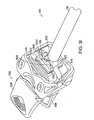
- Alignment protrusions 316, 322 of implant clip 300 cause proper alignment of grabber 160 ( Figs. 2A-2C ) with engagement protrusions 712, 722 of artificial disc 330 ( Fig. 4 ).
- Alignment protrusions 316, 322 can form alignment slot 323 as shown in at least Fig. 3A or an alignment window 325 as shown in Figs. 3C and 3G .
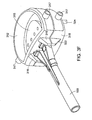
- Fig. 3I shows a perspective view of the implant clip of Fig. 3B attached to the grabber of Fig. 2C .
- Grabber 160 is in a closed position (i.e., trigger released) within outer sleeve 130 of insertion instrument 100.
- Grabber tips 162c are shown engaged to engagement indents 906 on artificial disc 900 which is contained within holders 312, 318 of implant clip 300.
- insertion instrument 100 and implant clip 300 will be explained with reference to the figures. Although reference is made to an artificial disc 330, its principles are applicable to spinal fusion cages.
- a user opens ( Fig. 3C ) implant clip 300 by depressing and holding opposite portions of shells 306, 308 at opposite ends of spring 302 ( Fig. 3B ) to an open position as shown in Fig. 3D .
- Opened clip 300 is placed over a selected artificial disc 330, causing implant holders 312, 318 to engage artificial disc 330 when shells 306, 308 are released.
- the user aligns grabber 160 ( Fig. 2A ) of implantation instrument 100 with alignment slot 323 on implant clip 300.
- the user squeezes trigger mechanism 120 ( Fig. 1 ) on implantation instrument 100, thereby causing grabber tips 162a, 162b to be inserted over engagement tabs 712, 722 on artificial disc 330 ( Fig. 4 ).
- grabber tips 162 are inserted over engagement tabs 712, 722, the user releases trigger mechanism 120, causing grabber tips 162 to engage engagement tabs 712, 722 on artificial disc 330 as shown in Fig. 5 .
- the user removes implant clip 300 from artificial disc 330 by opening and removing implant clip 300 from the now engaged artificial disc 330, as shown in Fig. 6A .
- the user aligns grabber 160 ( Figs. 2B and 2C ) of implantation instrument 100 with alignment window 325 on implant clip 300.
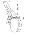
- the user squeezes trigger mechanism 120 ( Fig. 1 ) on implantation instrument 100, thereby causing grabber tips 162c, 162d to be inserted over engagement indents 906 on artificial disc 900 ( Fig. 3I and 6B ).
- grabber tips 162 are inserted over engagement indents 906, the user releases trigger mechanism 120, causing grabber tips 162 to engage engagement indents 906 on artificial disc 900 ( Fig. 3I ).
- the user removes implant clip 300 from artificial disc 900 by opening and removing implant clip 300 from the now engaged artificial disc 900, as shown in Fig. 6B .
- distraction instrument 950 is inserted over pins (not shown) that are secured into vertebral bodies 962, 964.
- Artificial disc 330 is passed between the forks of distraction instrument 950 using implantation instrument 100 ( Figs. 1A-1B ).
- guides 170 on insertion instrument 100 slidably engage slots in the forks of distraction instrument 950 to help the user guide artificial disc 330 into prepared disc space 970.
- the user squeezes trigger mechanism 120 ( Fig. 1A ) which releases artificial disc 330 in prepared disc space 970.
- the user can determine the desired position by observing cephalad markers 168 ( Figs. 3A-3B ) located on a surface of grabber 160.
- implantation instrument 100 can include depth control member 173 ( Fig. 1A ) such that artificial disc 330 can be inserted into prepared disc space 970 at a predetermined depth.
- Implantation instrument 100 and distraction instrument 950 are removed, causing superior vertebra 962 and inferior vertebra 964 to engage artificial disc 330.
Landscapes
- Health & Medical Sciences (AREA)
- Transplantation (AREA)
- Orthopedic Medicine & Surgery (AREA)
- Engineering & Computer Science (AREA)
- Biomedical Technology (AREA)
- Oral & Maxillofacial Surgery (AREA)
- Physical Education & Sports Medicine (AREA)
- Cardiology (AREA)
- Heart & Thoracic Surgery (AREA)
- Vascular Medicine (AREA)
- Life Sciences & Earth Sciences (AREA)
- Animal Behavior & Ethology (AREA)
- General Health & Medical Sciences (AREA)
- Public Health (AREA)
- Veterinary Medicine (AREA)
- Neurology (AREA)
- Prostheses (AREA)
- Dental Prosthetics (AREA)
Claims (13)
- Dispositif d'implantation d'implant (100), comprenant :(i) un châssis (110) muni d'un mécanisme de déclenchement (120), où le châssis inclut un axe de pivotement (122), et le mécanisme de déclenchement pivote autour de l'axe de pivotement dans le châssis ;(ii) un manchon extérieur (130) couplé mécaniquement au châssis ;(iii) un arbre intérieur (140) ayant un agrippeur (160) pour venir mécaniquement en prise avec un implant (330), l'arbre intérieure étant disposé d'une manière coulissante dans le manchon extérieur ; et(iv) un élément de retenue (150) pour diriger l'agrippeur vers une position fermée ;
où l'agrippeur comprend des pointes d'agrippeur (162c, 162d) pour venir en prise d'une manière mécanique et détachable avec l'implant, et où les pointes de l'agrippeur définissent une forme en queue d'aronde. - Dispositif selon la revendication 1, dans lequel l'élément de retenu est un ressort.
- Dispositif selon la revendication 1, comprenant en outre un bouton (170) couplé mécaniquement au manchon extérieur, le bouton amenant le manchon extérieur et l'arbre intérieur à tourner autour du châssis.
- Dispositif selon la revendication 1, incluant en outre une vis de réglage de traction (124) couplée d'une manière tournante au châssis pour réaliser une tension entre le mécanisme de déclenchement et l'arbre intérieur.
- Appareil pour l'insertion d'un implant dans un espace de disque préparé, comprenant un instrument de distraction et le dispositif de la revendication 1, dans lequel le dispositif comprend au moins une saillie (171) sur le manchon extérieur pour une mise en prise coulissante avec l'instrument de distraction.
- Dispositif selon la revendication 1, incluant en outre un élément de contrôle de profondeur (173) couplé d'une manière coulissante au manchon extérieur, l'élément de contrôle de profondeur étant prévu pour obtenir une profondeur d'insertion prédéterminée de l'implant.
- Dispositif selon la revendication 1, dans lequel les pointes de l'agrippeur comprennent une première paire de fentes pour la mise en prise avec une première patte d'engagement (712, 722) de l'implant et une deuxième paire de fentes pour la mise en prise avec une deuxième patte d'engagement (712, 722) de l'implant.
- Dispositif selon la revendication 7, dans lequel la première paire de fentes diffère en taille de la deuxième paire de fentes.
- Dispositif selon la revendication 7, dans lequel une fente de dimensionnement (166, 169) est située entre la première paire de fentes et la deuxième paire de fentes pour permettre une variation des différences dimensionnelles de pattes et de fentes.
- Dispositif selon la revendication 1, dans lequel l'agrippeur comprend au moins un marquage (168) pour identifier une position de l'implant.
- Dispositif selon la revendication 10, dans lequel le marquage est un axe (168a) situé sur une surface de l'agrippeur.
- Dispositif selon la revendication 10, dans lequel le marquage consiste en une pluralité de fentes usinées (168b) sur une surface de l'agrippeur.
- Dispositif selon la revendication 1, dans lequel l'agrippeur est couple d'une manière amovible à l'arbre intérieur.
Priority Applications (1)
| Application Number | Priority Date | Filing Date | Title |
|---|---|---|---|
| EP09173718A EP2149355B1 (fr) | 2003-12-31 | 2004-12-21 | Support d'implants de disques intervertébraux et dispositif d'implantation |
Applications Claiming Priority (2)
| Application Number | Priority Date | Filing Date | Title |
|---|---|---|---|
| US10/750,173 US8123757B2 (en) | 2003-12-31 | 2003-12-31 | Inserter instrument and implant clip |
| PCT/US2004/043149 WO2005065597A2 (fr) | 2003-12-31 | 2004-12-21 | Instrument d'insertion et pince a implant |
Related Child Applications (2)
| Application Number | Title | Priority Date | Filing Date |
|---|---|---|---|
| EP09173718A Division EP2149355B1 (fr) | 2003-12-31 | 2004-12-21 | Support d'implants de disques intervertébraux et dispositif d'implantation |
| EP09173718A Division-Into EP2149355B1 (fr) | 2003-12-31 | 2004-12-21 | Support d'implants de disques intervertébraux et dispositif d'implantation |
Publications (2)
| Publication Number | Publication Date |
|---|---|
| EP1699390A2 EP1699390A2 (fr) | 2006-09-13 |
| EP1699390B1 true EP1699390B1 (fr) | 2014-09-10 |
Family
ID=34701167
Family Applications (2)
| Application Number | Title | Priority Date | Filing Date |
|---|---|---|---|
| EP04815252.4A Expired - Lifetime EP1699390B1 (fr) | 2003-12-31 | 2004-12-21 | Instrument d'insertion pour implant |
| EP09173718A Expired - Lifetime EP2149355B1 (fr) | 2003-12-31 | 2004-12-21 | Support d'implants de disques intervertébraux et dispositif d'implantation |
Family Applications After (1)
| Application Number | Title | Priority Date | Filing Date |
|---|---|---|---|
| EP09173718A Expired - Lifetime EP2149355B1 (fr) | 2003-12-31 | 2004-12-21 | Support d'implants de disques intervertébraux et dispositif d'implantation |
Country Status (10)
| Country | Link |
|---|---|
| US (2) | US8123757B2 (fr) |
| EP (2) | EP1699390B1 (fr) |
| JP (1) | JP2007516789A (fr) |
| KR (1) | KR20060114712A (fr) |
| CN (1) | CN1921810A (fr) |
| AU (1) | AU2004312038A1 (fr) |
| BR (1) | BRPI0418327A (fr) |
| CA (1) | CA2551301A1 (fr) |
| MX (1) | MXPA06007513A (fr) |
| WO (1) | WO2005065597A2 (fr) |
Families Citing this family (123)
| Publication number | Priority date | Publication date | Assignee | Title |
|---|---|---|---|---|
| AU780719B2 (en) | 1999-07-02 | 2005-04-14 | Spine Solutions Inc. | Intervertebral implant |
| EP1779815A3 (fr) | 1999-09-14 | 2007-06-27 | Spine Solutions Inc. | Instrument de mise en place pour un implant entre des vertèbres |
| US20080027548A9 (en) | 2002-04-12 | 2008-01-31 | Ferree Bret A | Spacerless artificial disc replacements |
| US8038713B2 (en) | 2002-04-23 | 2011-10-18 | Spinecore, Inc. | Two-component artificial disc replacements |
| US6706068B2 (en) | 2002-04-23 | 2004-03-16 | Bret A. Ferree | Artificial disc replacements with natural kinematics |
| US7204852B2 (en) | 2002-12-13 | 2007-04-17 | Spine Solutions, Inc. | Intervertebral implant, insertion tool and method of inserting same |
| US7887539B2 (en) * | 2003-01-24 | 2011-02-15 | Depuy Spine, Inc. | Spinal rod approximators |
| US7988698B2 (en) | 2003-01-28 | 2011-08-02 | Depuy Spine, Inc. | Spinal rod approximator |
| US6908484B2 (en) | 2003-03-06 | 2005-06-21 | Spinecore, Inc. | Cervical disc replacement |
| US7491204B2 (en) * | 2003-04-28 | 2009-02-17 | Spine Solutions, Inc. | Instruments and method for preparing an intervertebral space for receiving an artificial disc implant |
| US7803162B2 (en) | 2003-07-21 | 2010-09-28 | Spine Solutions, Inc. | Instruments and method for inserting an intervertebral implant |
| US7842044B2 (en) | 2003-12-17 | 2010-11-30 | Depuy Spine, Inc. | Instruments and methods for bone anchor engagement and spinal rod reduction |
| BRPI0417670A (pt) | 2003-12-17 | 2007-04-03 | Depuy Spine Inc | instrumentos e métodos para acoplamento de áncora óssea e redução de haste espinhal |
| US8123757B2 (en) | 2003-12-31 | 2012-02-28 | Depuy Spine, Inc. | Inserter instrument and implant clip |
| US7611517B2 (en) * | 2004-02-27 | 2009-11-03 | Warsaw Orthopedic, Inc. | Rod reducer |
| US7294134B2 (en) * | 2004-07-28 | 2007-11-13 | Weber Instrumente Gmbh | Surgical instrument for the introduction of a multi-component intervertebral prosthesis |
| US7585326B2 (en) * | 2004-08-06 | 2009-09-08 | Spinalmotion, Inc. | Methods and apparatus for intervertebral disc prosthesis insertion |
| DE102004043996B4 (de) * | 2004-09-08 | 2008-04-17 | Aesculap Ag & Co. Kg | Chirurgisches Instrument und Implantatsystem |
| US7951175B2 (en) | 2005-03-04 | 2011-05-31 | Depuy Spine, Inc. | Instruments and methods for manipulating a vertebra |
| US7951172B2 (en) | 2005-03-04 | 2011-05-31 | Depuy Spine Sarl | Constrained motion bone screw assembly |
| US20060217731A1 (en) * | 2005-03-28 | 2006-09-28 | Sdgi Holdings, Inc. | X-ray and fluoroscopic visualization slots |
| US20060264959A1 (en) * | 2005-05-23 | 2006-11-23 | Custom Spine, Inc. | Rod pusher |
| US8777959B2 (en) | 2005-05-27 | 2014-07-15 | Spinecore, Inc. | Intervertebral disc and insertion methods therefor |
| US20060293692A1 (en) | 2005-06-02 | 2006-12-28 | Whipple Dale E | Instruments and methods for manipulating a spinal fixation element |
| FR2890851B1 (fr) * | 2005-09-21 | 2008-06-20 | Abbott Spine Sa | Ancillaire de mise en tension d'un lien souple. |
| US7771430B2 (en) * | 2005-09-29 | 2010-08-10 | K2M, Inc. | Single action anti-torque rod reducer |
| US7988695B2 (en) * | 2005-12-21 | 2011-08-02 | Theken Spine, Llc | Articulated delivery instrument |
| US7918889B2 (en) * | 2006-02-27 | 2011-04-05 | Warsaw Orthopedic, Inc. | Expandable spinal prosthetic devices and associated methods |
| US7976549B2 (en) * | 2006-03-23 | 2011-07-12 | Theken Spine, Llc | Instruments for delivering spinal implants |
| US8303601B2 (en) | 2006-06-07 | 2012-11-06 | Stryker Spine | Collet-activated distraction wedge inserter |
| WO2008014258A2 (fr) | 2006-07-24 | 2008-01-31 | Spine Solutions, Inc. | Implant intervertébral avec quille |
| WO2008016872A2 (fr) | 2006-07-31 | 2008-02-07 | Synthes (U.S.A.) | guide de forage/fraisage, et systÈme de prÉparation de dÉcoupage de CARÈNE |
| US8506636B2 (en) * | 2006-09-08 | 2013-08-13 | Theken Spine, Llc | Offset radius lordosis |
| US8414616B2 (en) * | 2006-09-12 | 2013-04-09 | Pioneer Surgical Technology, Inc. | Mounting devices for fixation devices and insertion instruments used therewith |
| FR2908978B1 (fr) * | 2006-11-28 | 2012-08-03 | Spineart Sa | Porte-protheses et leurs applications. |
| US9039768B2 (en) | 2006-12-22 | 2015-05-26 | Medos International Sarl | Composite vertebral spacers and instrument |
| US8172847B2 (en) * | 2007-03-29 | 2012-05-08 | Depuy Spine, Inc. | In-line rod reduction device and methods |
| US20080255574A1 (en) * | 2007-04-13 | 2008-10-16 | Zimmer Technology, Inc. | Instrument for insertion of prosthetic components |
| US8579910B2 (en) | 2007-05-18 | 2013-11-12 | DePuy Synthes Products, LLC | Insertion blade assembly and method of use |
| US8486081B2 (en) * | 2007-07-23 | 2013-07-16 | DePuy Synthes Products, LLC | Implant insertion device and method |
| US20090030420A1 (en) * | 2007-07-26 | 2009-01-29 | Depuy Spine, Inc. | Spinal rod reduction instruments and methods for use |
| JP4445535B2 (ja) * | 2007-09-19 | 2010-04-07 | 富士通株式会社 | データ転送装置,情報処理システム,データ転送プログラム及び同プログラムを記録したコンピュータ読取可能な記録媒体 |
| US8790348B2 (en) | 2007-09-28 | 2014-07-29 | Depuy Spine, Inc. | Dual pivot instrument for reduction of a fixation element and method of use |
| US8182537B2 (en) * | 2007-10-30 | 2012-05-22 | Aesculap Implant Systems, Llc | Vertebral body replacement device and method for use to maintain a space between two vertebral bodies within a spine |
| US20090112325A1 (en) * | 2007-10-30 | 2009-04-30 | Biospine, Llc | Footplate member and a method for use in a vertebral body replacement device |
| US8591587B2 (en) | 2007-10-30 | 2013-11-26 | Aesculap Implant Systems, Llc | Vertebral body replacement device and method for use to maintain a space between two vertebral bodies within a spine |
| US8142441B2 (en) * | 2008-10-16 | 2012-03-27 | Aesculap Implant Systems, Llc | Surgical instrument and method of use for inserting an implant between two bones |
| US8241294B2 (en) * | 2007-12-19 | 2012-08-14 | Depuy Spine, Inc. | Instruments for expandable corpectomy spinal fusion cage |
| US8241363B2 (en) * | 2007-12-19 | 2012-08-14 | Depuy Spine, Inc. | Expandable corpectomy spinal fusion cage |
| WO2009088927A1 (fr) * | 2008-01-04 | 2009-07-16 | Illuminoss Medical, Inc. | Appareil et procédés pour séparer un dispositif de fixation d'os interne d'un dispositif d'introduction |
| CA2847598A1 (fr) * | 2008-01-18 | 2009-07-23 | Spinecore, Inc. | Instruments et procedes d'introduction d'implants intervertebraux artificiels |
| US8608746B2 (en) | 2008-03-10 | 2013-12-17 | DePuy Synthes Products, LLC | Derotation instrument with reduction functionality |
| US8709015B2 (en) | 2008-03-10 | 2014-04-29 | DePuy Synthes Products, LLC | Bilateral vertebral body derotation system |
| US20090248092A1 (en) | 2008-03-26 | 2009-10-01 | Jonathan Bellas | Posterior Intervertebral Disc Inserter and Expansion Techniques |
| US10973556B2 (en) | 2008-06-17 | 2021-04-13 | DePuy Synthes Products, Inc. | Adjustable implant assembly |
| CA2747660A1 (fr) * | 2008-12-22 | 2010-07-01 | DePuy Synthes Products, Inc. | Implant orthopedique avec quille flexible |
| US8142435B2 (en) | 2009-02-19 | 2012-03-27 | Aesculap Implant Systems, Llc | Multi-functional surgical instrument and method of use for inserting an implant between two bones |
| US9526620B2 (en) | 2009-03-30 | 2016-12-27 | DePuy Synthes Products, Inc. | Zero profile spinal fusion cage |
| US8906033B2 (en) * | 2009-03-30 | 2014-12-09 | DePuy Synthes Products, LLC | Cervical motion disc inserter |
| US8876905B2 (en) * | 2009-04-29 | 2014-11-04 | DePuy Synthes Products, LLC | Minimally invasive corpectomy cage and instrument |
| US8206394B2 (en) | 2009-05-13 | 2012-06-26 | Depuy Spine, Inc. | Torque limited instrument for manipulating a spinal rod relative to a bone anchor |
| US9393129B2 (en) | 2009-12-10 | 2016-07-19 | DePuy Synthes Products, Inc. | Bellows-like expandable interbody fusion cage |
| US9480511B2 (en) | 2009-12-17 | 2016-11-01 | Engage Medical Holdings, Llc | Blade fixation for ankle fusion and arthroplasty |
| US8545505B2 (en) | 2010-01-15 | 2013-10-01 | Pioneer Surgical Technology, Inc. | Low friction rod persuader |
| US9301853B2 (en) * | 2010-04-09 | 2016-04-05 | DePuy Synthes Products, Inc. | Holder for implantation and extraction of prosthesis |
| US8858636B2 (en) | 2010-04-09 | 2014-10-14 | DePuy Synthes Products, LLC | Intervertebral implant |
| US20120078373A1 (en) | 2010-09-23 | 2012-03-29 | Thomas Gamache | Stand alone intervertebral fusion device |
| EP2433571B1 (fr) | 2010-09-23 | 2022-09-28 | Tornier, Inc. | Système pour indiquer la profondeur d'un dispositif d'insertion de l'ancrage d'os |
| US11529241B2 (en) | 2010-09-23 | 2022-12-20 | DePuy Synthes Products, Inc. | Fusion cage with in-line single piece fixation |
| US20120078372A1 (en) | 2010-09-23 | 2012-03-29 | Thomas Gamache | Novel implant inserter having a laterally-extending dovetail engagement feature |
| EP2651341B1 (fr) | 2010-12-16 | 2017-01-04 | Engage Medical Holdings, LLC | Systèmes et procédés d'arthroplastie |
| EP2685938B1 (fr) | 2011-02-14 | 2015-08-26 | Hyun Bae, M.D. | Système de retrait d'ancrage osseux |
| US8764756B2 (en) | 2011-02-22 | 2014-07-01 | K2M, Inc. | Single action anti-torque rod reducer |
| US9248028B2 (en) | 2011-09-16 | 2016-02-02 | DePuy Synthes Products, Inc. | Removable, bone-securing cover plate for intervertebral fusion cage |
| FR2981264B1 (fr) * | 2011-10-17 | 2013-11-29 | Osteal Medical Lab | Pince de prehension d'implant intervertebral, kit et ensemble de manipulation d'une telle pince |
| US9254130B2 (en) | 2011-11-01 | 2016-02-09 | Hyun Bae | Blade anchor systems for bone fusion |
| EP2604231B1 (fr) * | 2011-12-12 | 2016-04-06 | Biotronik AG | Dispositif de libération pour libérer un implant médical d'un cathéter ainsi que cathéter avec dispositif de libération |
| US8584853B2 (en) | 2012-02-16 | 2013-11-19 | Biomedical Enterprises, Inc. | Method and apparatus for an orthopedic fixation system |
| US9271836B2 (en) | 2012-03-06 | 2016-03-01 | DePuy Synthes Products, Inc. | Nubbed plate |
| KR101408762B1 (ko) * | 2012-03-12 | 2014-06-18 | 제이엠티(주) | 좌우 분리형 임플란트의 결합장치 |
| US10238382B2 (en) | 2012-03-26 | 2019-03-26 | Engage Medical Holdings, Llc | Blade anchor for foot and ankle |
| KR101373287B1 (ko) * | 2012-04-04 | 2014-03-11 | (주) 서한케어 | 척추체 극돌기간 스페이서 이식 시술용 의료기구 |
| US8939977B2 (en) | 2012-07-10 | 2015-01-27 | Illuminoss Medical, Inc. | Systems and methods for separating bone fixation devices from introducer |
| US10182921B2 (en) | 2012-11-09 | 2019-01-22 | DePuy Synthes Products, Inc. | Interbody device with opening to allow packing graft and other biologics |
| US9265533B2 (en) | 2013-09-04 | 2016-02-23 | Aesculap Implant Systems, Llc | Rod persuader, system and method |
| US9452000B2 (en) | 2013-10-07 | 2016-09-27 | K2M, Inc. | Rod reducer |
| EP3406213B1 (fr) * | 2013-10-09 | 2023-10-25 | Stryker European Operations Holdings LLC | Système chirurgical avec implant intervertébral, plaque vertébrale et entretoise de couplage |
| US9730802B1 (en) | 2014-01-14 | 2017-08-15 | Nuvasive, Inc. | Spinal fusion implant and related methods |
| US9808354B2 (en) | 2014-01-17 | 2017-11-07 | Stryker European Holdings I, Llc | Implant insertion tool |
| US10456130B2 (en) | 2014-05-07 | 2019-10-29 | Biomedical Enterprises, Inc. | Method and apparatus for loading and implanting a shape memory implant |
| US10456131B2 (en) | 2014-05-07 | 2019-10-29 | Biomedical Enterprises, Inc. | Method and apparatus for loading and implanting a shape memory implant |
| US9681961B2 (en) * | 2014-08-01 | 2017-06-20 | Warsaw Orthopedic, Inc. | Surgical instrument system and method |
| US9943344B2 (en) | 2015-01-15 | 2018-04-17 | K2M, Inc. | Rod reducer |
| EP3288473B1 (fr) | 2015-04-30 | 2022-12-28 | K2M, Inc. | Réducteur à tige |
| RU2730996C2 (ru) | 2015-06-03 | 2020-08-26 | Интарсия Терапьютикс, Инк. | Системы установки и извлечения имплантата |
| CN107920818B (zh) | 2015-09-03 | 2021-02-09 | 生物医药企业公司 | 弹性矫形植入物及其制造方法 |
| GB201519629D0 (en) * | 2015-11-06 | 2015-12-23 | Embody Orthopaedic Ltd | Holder for resurfacing head implant |
| US9937054B2 (en) | 2016-01-28 | 2018-04-10 | Warsaw Orthopedic, Inc. | Expandable implant and insertion tool |
| US10524843B2 (en) | 2016-05-06 | 2020-01-07 | K2M, Inc. | Rotation shaft for a rod reducer |
| USD840030S1 (en) | 2016-06-02 | 2019-02-05 | Intarcia Therapeutics, Inc. | Implant placement guide |
| USD860451S1 (en) | 2016-06-02 | 2019-09-17 | Intarcia Therapeutics, Inc. | Implant removal tool |
| CN106137475B (zh) * | 2016-07-28 | 2018-01-16 | 农鲁明 | 假体植入器 |
| US10390955B2 (en) | 2016-09-22 | 2019-08-27 | Engage Medical Holdings, Llc | Bone implants |
| US10485590B2 (en) | 2017-01-18 | 2019-11-26 | K2M, Inc. | Rod reducing device |
| US10456272B2 (en) | 2017-03-03 | 2019-10-29 | Engage Uni Llc | Unicompartmental knee arthroplasty |
| US11540928B2 (en) | 2017-03-03 | 2023-01-03 | Engage Uni Llc | Unicompartmental knee arthroplasty |
| US11224511B2 (en) * | 2017-04-18 | 2022-01-18 | Edwards Lifesciences Corporation | Heart valve sealing devices and delivery devices therefor |
| US10940016B2 (en) | 2017-07-05 | 2021-03-09 | Medos International Sarl | Expandable intervertebral fusion cage |
| US10842487B2 (en) * | 2017-10-20 | 2020-11-24 | Biomedical Enterprises, Inc. | Method and apparatus for loading and implanting a shape memory implant |
| US10966762B2 (en) | 2017-12-15 | 2021-04-06 | Medos International Sarl | Unilateral implant holders and related methods |
| US10932922B2 (en) | 2018-04-20 | 2021-03-02 | JWD Products, LLC | Spinal implant insertion tool |
| US11324609B2 (en) | 2018-04-20 | 2022-05-10 | JWD Products, LLC | Spinal implant insertion tool |
| US11135030B2 (en) | 2018-06-15 | 2021-10-05 | Verb Surgical Inc. | User interface device having finger clutch |
| USD933219S1 (en) | 2018-07-13 | 2021-10-12 | Intarcia Therapeutics, Inc. | Implant removal tool and assembly |
| TWI677316B (zh) * | 2018-09-19 | 2019-11-21 | 台灣微創醫療器材股份有限公司 | 脊椎植入物持取裝置 |
| US11291482B2 (en) | 2019-03-21 | 2022-04-05 | Medos International Sarl | Rod reducers and related methods |
| US11291481B2 (en) | 2019-03-21 | 2022-04-05 | Medos International Sarl | Rod reducers and related methods |
| USD1004774S1 (en) | 2019-03-21 | 2023-11-14 | Medos International Sarl | Kerrison rod reducer |
| US11219536B2 (en) | 2019-05-01 | 2022-01-11 | Simplify Medical Pty Ltd | Intervertebral prosethetic disc placement and removal systems |
| US12042386B2 (en) | 2020-01-29 | 2024-07-23 | DePuy Synthes Products, Inc. | Shape memory implants and methods and apparatus for the loading and implanting thereof |
| US11523820B2 (en) | 2020-01-29 | 2022-12-13 | DePuy Synthes Products, Inc. | Shape memory implants and a method and apparatus for the loading and implanting thereof |
| US12318121B2 (en) | 2020-11-09 | 2025-06-03 | Medos International Sàrl | Biplanar forceps reducers and methods of use |
| JP2024538403A (ja) | 2021-11-19 | 2024-10-18 | メドス・インターナショナル・エスエイアールエル | 整復係止機構 |
Citations (1)
| Publication number | Priority date | Publication date | Assignee | Title |
|---|---|---|---|---|
| WO2002007654A2 (fr) * | 2000-07-26 | 2002-01-31 | Osteotech, Inc. | Espaceur intervertebral et instrumentation d'insertion d'implant |
Family Cites Families (143)
| Publication number | Priority date | Publication date | Assignee | Title |
|---|---|---|---|---|
| US132057A (en) | 1872-10-08 | Improvement in adjustable slide-wrenches | ||
| US666006A (en) * | 1899-11-25 | 1901-01-15 | Automatic Camera Company | Photographic shutter. |
| US1539987A (en) | 1924-02-11 | 1925-06-02 | John A Bell | Adjustable wrench |
| US3141583A (en) * | 1962-03-23 | 1964-07-21 | William L Brickson | Injection gun |
| US3752161A (en) * | 1971-08-02 | 1973-08-14 | Minnesota Mining & Mfg | Fluid operated surgical tool |
| US3835860A (en) * | 1973-06-21 | 1974-09-17 | H Garretson | Surgical bone punch |
| CH609774A5 (fr) * | 1977-01-21 | 1979-03-15 | Semperit Ag | |
| AR218795A1 (es) * | 1979-12-11 | 1980-06-30 | Derechinsky V | Instrumento porta-clips para el "clipado" de vasos sanguineos |
| US4512345A (en) * | 1982-09-30 | 1985-04-23 | United States Surgical Corporation | Surgical clip applying apparatus, and clips and clip train for use therein |
| US4592347A (en) | 1983-10-11 | 1986-06-03 | Mahruki Nimetullah M T | Retraction device |
| EP0176728B1 (fr) * | 1984-09-04 | 1989-07-26 | Humboldt-Universität zu Berlin | Prothèse pour disques intervertébraux |
| DE3809793A1 (de) | 1988-03-23 | 1989-10-05 | Link Waldemar Gmbh Co | Chirurgischer instrumentensatz |
| US5018412A (en) | 1988-04-25 | 1991-05-28 | Wylie Iii Albert A | Open-end ratchet wrench |
| US5484437A (en) * | 1988-06-13 | 1996-01-16 | Michelson; Gary K. | Apparatus and method of inserting spinal implants |
| CA1333209C (fr) * | 1988-06-28 | 1994-11-29 | Gary Karlin Michelson | Implants artificiels pour la soudure osseuse intervertebrale |
| FR2636227A1 (fr) | 1988-09-09 | 1990-03-16 | Fabrication Materiel Orthopedi | Dispositif intercorporeal rachidien de maintien d'un ecartement normal entre deux vertebres |
| US5486185A (en) | 1989-01-30 | 1996-01-23 | Dexide, Inc. | Surgical apparatus |
| US6099550A (en) * | 1989-12-05 | 2000-08-08 | Yoon; Inbae | Surgical instrument having jaws and an operating channel and method for use thereof |
| US5236460A (en) * | 1990-02-12 | 1993-08-17 | Midas Rex Pneumatic Tools, Inc. | Vertebral body prosthesis |
| FR2659226B1 (fr) * | 1990-03-07 | 1992-05-29 | Jbs Sa | Prothese pour disques intervertebraux et ses instruments d'implantation. |
| US5383888A (en) | 1992-02-12 | 1995-01-24 | United States Surgical Corporation | Articulating endoscopic surgical apparatus |
| US5431654A (en) * | 1991-09-30 | 1995-07-11 | Stryker Corporation | Bone cement injector |
| GB9121132D0 (en) | 1991-10-04 | 1991-11-13 | Johnson & Johnson Orthopaedics | An acetabular cup inserter |
| GB9125798D0 (en) * | 1991-12-04 | 1992-02-05 | Customflex Limited | Improvements in or relating to spinal vertebrae implants |
| US5425773A (en) * | 1992-01-06 | 1995-06-20 | Danek Medical, Inc. | Intervertebral disk arthroplasty device |
| US5258031A (en) | 1992-01-06 | 1993-11-02 | Danek Medical | Intervertebral disk arthroplasty |
| US5222973A (en) | 1992-03-09 | 1993-06-29 | Sharpe Endosurgical Corporation | Endoscopic grasping tool surgical instrument |
| DE4208116C2 (de) * | 1992-03-13 | 1995-08-03 | Link Waldemar Gmbh Co | Bandscheibenendoprothese |
| EP0566810B1 (fr) | 1992-04-21 | 1996-08-14 | SULZER Medizinaltechnik AG | Disque intervertébral artificiel |
| US5300081A (en) * | 1992-10-09 | 1994-04-05 | United States Surgical Corporation | Surgical clip applier having clip advancement control |
| US5676701A (en) | 1993-01-14 | 1997-10-14 | Smith & Nephew, Inc. | Low wear artificial spinal disc |
| DE4319829C1 (de) | 1993-06-16 | 1994-08-25 | Lerch Karl Dieter | Set zur Behandlung von Gefäßmißbildungen |
| US5360430A (en) | 1993-07-29 | 1994-11-01 | Lin Chih I | Intervertebral locking device |
| US5458641A (en) | 1993-09-08 | 1995-10-17 | Ramirez Jimenez; Juan J. | Vertebral body prosthesis |
| US5443514A (en) * | 1993-10-01 | 1995-08-22 | Acromed Corporation | Method for using spinal implants |
| US5431658A (en) * | 1994-02-14 | 1995-07-11 | Moskovich; Ronald | Facilitator for vertebrae grafts and prostheses |
| FR2717068B1 (fr) | 1994-03-14 | 1996-04-26 | Biomat | Cage intersomatique vertébrale. |
| US5591170A (en) * | 1994-10-14 | 1997-01-07 | Genesis Orthopedics | Intramedullary bone cutting saw |
| US5873886A (en) * | 1995-04-04 | 1999-02-23 | United States Surgical Corporation | Surgical cutting apparatus |
| US5797927A (en) * | 1995-09-22 | 1998-08-25 | Yoon; Inbae | Combined tissue clamping and suturing instrument |
| US5782830A (en) * | 1995-10-16 | 1998-07-21 | Sdgi Holdings, Inc. | Implant insertion device |
| US5683465A (en) | 1996-03-18 | 1997-11-04 | Shinn; Gary Lee | Artificial intervertebral disk prosthesis |
| WO1997038634A1 (fr) * | 1996-04-18 | 1997-10-23 | Applied Medical Resources Corporation | Procede et applicateur de pince endoscopique adaptable |
| US5782832A (en) * | 1996-10-01 | 1998-07-21 | Surgical Dynamics, Inc. | Spinal fusion implant and method of insertion thereof |
| US5895428A (en) * | 1996-11-01 | 1999-04-20 | Berry; Don | Load bearing spinal joint implant |
| AU6268798A (en) | 1997-02-11 | 1998-08-26 | Gary Karlin Michelson | Anterior cervical plating system, instrumentation, and method of installation |
| FR2762985B1 (fr) * | 1997-05-06 | 1999-08-20 | Visco | Dispositif de chirurgie modulaire pour la chirurgie endoscopique et la chirurgie classique |
| US5938678A (en) * | 1997-06-11 | 1999-08-17 | Endius Incorporated | Surgical instrument |
| US5851207A (en) | 1997-07-01 | 1998-12-22 | Synthes (U.S.A.) | Freely separable surgical drill guide and plate |
| US6146421A (en) | 1997-08-04 | 2000-11-14 | Gordon, Maya, Roberts And Thomas, Number 1, Llc | Multiple axis intervertebral prosthesis |
| EP1001723A1 (fr) * | 1997-08-04 | 2000-05-24 | Gordon, Maya. Roberts & Thomas Number 1 LLC | Prothese intervertebrale a axes multiples |
| US6488707B1 (en) * | 1997-08-20 | 2002-12-03 | Thinoptx, Inc. | Method of implanting a deformable intraocular corrective lens |
| US5899941A (en) * | 1997-12-09 | 1999-05-04 | Chubu Bearing Kabushiki Kaisha | Artificial intervertebral disk |
| US6159215A (en) | 1997-12-19 | 2000-12-12 | Depuy Acromed, Inc. | Insertion instruments and method for delivering a vertebral body spacer |
| WO1999034737A1 (fr) | 1998-01-05 | 1999-07-15 | Tegementa, L.L.C | Dispositif d'ecartement destine a des interventions sur des disques intervertebraux |
| US5989291A (en) | 1998-02-26 | 1999-11-23 | Third Millennium Engineering, Llc | Intervertebral spacer device |
| GB9804473D0 (en) * | 1998-03-02 | 1998-04-29 | Benoist Girard & Cie | Prosthesis inserter |
| EP0940127B1 (fr) | 1998-03-02 | 2003-11-26 | Benoist Girard Sas | Dispositif d'insertion de prothèse |
| FR2777443B1 (fr) * | 1998-04-21 | 2000-06-30 | Tornier Sa | Ancillaire pour la mise en place et le retrait d'un implant et plus particulierement d'une ancre de suture |
| US6019792A (en) * | 1998-04-23 | 2000-02-01 | Cauthen Research Group, Inc. | Articulating spinal implant |
| JP2002512079A (ja) * | 1998-04-23 | 2002-04-23 | コーゼン リサーチ グループ インク. | 関節結合脊椎インプラント |
| EP1681021A3 (fr) | 1998-06-09 | 2009-04-15 | Warsaw Orthopedic, Inc. | Elément abrasif pour la préparation d'un espace entre vertèbres voisines |
| US6063121A (en) * | 1998-07-29 | 2000-05-16 | Xavier; Ravi | Vertebral body prosthesis |
| WO2000007510A1 (fr) | 1998-08-06 | 2000-02-17 | Jordan Medical Llc | Cartouche de vis chirurgicales, magasin/porte-vis et tournevis de type pistolet pour fixation d'os |
| ES2317604T3 (es) * | 1998-10-02 | 2009-04-16 | Synthes Gmbh | Separador de espacio intervertebral. |
| US6652534B2 (en) * | 1998-10-20 | 2003-11-25 | St. Francis Medical Technologies, Inc. | Apparatus and method for determining implant size |
| US6113637A (en) | 1998-10-22 | 2000-09-05 | Sofamor Danek Holdings, Inc. | Artificial intervertebral joint permitting translational and rotational motion |
| US6371986B1 (en) | 1998-10-27 | 2002-04-16 | George W. Bagby | Spinal fusion device, bone joining implant, and vertebral fusion implant |
| US6174311B1 (en) * | 1998-10-28 | 2001-01-16 | Sdgi Holdings, Inc. | Interbody fusion grafts and instrumentation |
| FR2787019B1 (fr) * | 1998-12-11 | 2001-03-02 | Dimso Sa | Prothese de disque intervertebral a comportement mecanique ameliore |
| FR2787016B1 (fr) * | 1998-12-11 | 2001-03-02 | Dimso Sa | Prothese de disque intervertebral |
| DE29901611U1 (de) * | 1999-01-30 | 1999-04-22 | Aesculap AG & Co. KG, 78532 Tuttlingen | Chirurgisches Instrument zum Einführen von Zwischenwirbelimplantaten |
| US6368350B1 (en) * | 1999-03-11 | 2002-04-09 | Sulzer Spine-Tech Inc. | Intervertebral disc prosthesis and method |
| US6332887B1 (en) * | 1999-04-06 | 2001-12-25 | Benjamin D. Knox | Spinal fusion instrumentation system |
| EP1057462B1 (fr) * | 1999-05-21 | 2003-04-02 | Waldemar Link (GmbH & Co.) | Endoprothèse intervertébrale avec une plaque de connexion dentée |
| US20020128714A1 (en) | 1999-06-04 | 2002-09-12 | Mark Manasas | Orthopedic implant and method of making metal articles |
| US6520996B1 (en) * | 1999-06-04 | 2003-02-18 | Depuy Acromed, Incorporated | Orthopedic implant |
| US7201776B2 (en) * | 1999-10-08 | 2007-04-10 | Ferree Bret A | Artificial intervertebral disc replacements with endplates |
| US6524318B1 (en) | 1999-10-18 | 2003-02-25 | Sulzer Spine-Tech Inc. | Spinal surgery instruments and methods |
| US6395034B1 (en) * | 1999-11-24 | 2002-05-28 | Loubert Suddaby | Intervertebral disc prosthesis |
| US6319257B1 (en) | 1999-12-20 | 2001-11-20 | Kinamed, Inc. | Inserter assembly |
| US6447512B1 (en) | 2000-01-06 | 2002-09-10 | Spinal Concepts, Inc. | Instrument and method for implanting an interbody fusion device |
| DE20000941U1 (de) | 2000-01-20 | 2000-03-23 | Liu, Kuo Chen, Da Li, Taichung | Selbstjustierendes Werkzeug |
| US6592578B2 (en) * | 2000-02-24 | 2003-07-15 | Howmedica Leibinger, Inc. | Device for locally heating a bioabsorbable plate |
| FR2805733B1 (fr) * | 2000-03-03 | 2002-06-07 | Scient X | Prothese discale pour vertebre cervicale |
| US6358268B1 (en) * | 2000-03-06 | 2002-03-19 | Robert B. Hunt | Surgical instrument |
| US6296665B1 (en) | 2000-03-20 | 2001-10-02 | Electro-Biology, Inc. | Method and apparatus for spinal fixation |
| US6478800B1 (en) * | 2000-05-08 | 2002-11-12 | Depuy Acromed, Inc. | Medical installation tool |
| US6593511B1 (en) * | 2000-05-12 | 2003-07-15 | Bioseek, Inc. | Models of chronic and acute inflammatory diseases |
| US6375382B1 (en) * | 2000-06-08 | 2002-04-23 | Alain Clavet | Crank handle assembly for casement window |
| EP1363565A2 (fr) | 2000-08-08 | 2003-11-26 | SDGI Holdings, Inc. | Prothese d'articulation implantable |
| US20020035400A1 (en) * | 2000-08-08 | 2002-03-21 | Vincent Bryan | Implantable joint prosthesis |
| US6692501B2 (en) * | 2000-12-14 | 2004-02-17 | Gary K. Michelson | Spinal interspace shaper |
| US7153304B2 (en) | 2000-12-29 | 2006-12-26 | Zimmer Trabecular Metal Technology, Inc. | Instrument system for preparing a disc space between adjacent vertebral bodies to receive a repair device |
| US6663637B2 (en) | 2001-01-02 | 2003-12-16 | Robert A Dixon | Vertebral distraction stabilizer |
| US6439439B1 (en) * | 2001-01-12 | 2002-08-27 | Telios Orthopedic Systems, Inc. | Bone cement delivery apparatus and hand-held fluent material dispensing apparatus |
| US6887274B2 (en) * | 2001-02-15 | 2005-05-03 | Spinecore, Inc. | Intervertebral spacer device utilizing a belleville washer having radially spaced concentric grooves |
| US7575576B2 (en) | 2001-07-16 | 2009-08-18 | Spinecore, Inc. | Wedge ramp distractor and related methods for use in implanting artificial intervertebral discs |
| US6989032B2 (en) * | 2001-07-16 | 2006-01-24 | Spinecore, Inc. | Artificial intervertebral disc |
| US6740117B2 (en) * | 2001-02-15 | 2004-05-25 | Spinecore, Inc. | Intervertebral spacer device having a radially thinning slotted belleville spring |
| US20020111687A1 (en) * | 2001-02-15 | 2002-08-15 | Ralph James D. | Intervertebral spacer device utilizing a belleville washer having radially extending grooves |
| US6673113B2 (en) | 2001-10-18 | 2004-01-06 | Spinecore, Inc. | Intervertebral spacer device having arch shaped spring elements |
| US6669730B2 (en) * | 2001-02-15 | 2003-12-30 | Spinecore, Inc. | Intervertebral spacer device utilizing a spirally slotted belleville washer having radially extending grooves |
| US6863688B2 (en) * | 2001-02-15 | 2005-03-08 | Spinecore, Inc. | Intervertebral spacer device utilizing a spirally slotted belleville washer having radially spaced concentric grooves |
| US20020111682A1 (en) * | 2001-02-15 | 2002-08-15 | Ralph James D. | Intervertebral spacer device having a radially thinning belleville spring |
| US6764515B2 (en) * | 2001-02-15 | 2004-07-20 | Spinecore, Inc. | Intervertebral spacer device utilizing a spirally slotted belleville washer and a rotational mounting |
| US7169182B2 (en) * | 2001-07-16 | 2007-01-30 | Spinecore, Inc. | Implanting an artificial intervertebral disc |
| US7604664B2 (en) * | 2001-07-16 | 2009-10-20 | Spinecore, Inc. | Spinal baseplates with ball joint coupling and a retaining member |
| US6575978B2 (en) * | 2001-04-05 | 2003-06-10 | Spineology, Inc. | Circumferential resecting reamer tool |
| US6440142B1 (en) | 2001-04-27 | 2002-08-27 | Third Millennium Engineering, Llc | Femoral ring loader |
| US7695478B2 (en) | 2001-07-16 | 2010-04-13 | Spinecore, Inc. | Insertion tool for use with intervertebral spacers |
| US7118599B2 (en) * | 2001-07-16 | 2006-10-10 | Spinecore, Inc. | Artificial intervertebral disc |
| US6375682B1 (en) | 2001-08-06 | 2002-04-23 | Lewis W. Fleischmann | Collapsible, rotatable and expandable spinal hydraulic prosthetic device |
| US20030033016A1 (en) * | 2001-08-07 | 2003-02-13 | Gyrus Group Plc | Implant sheath |
| US6648891B2 (en) | 2001-09-14 | 2003-11-18 | The Regents Of The University Of California | System and method for fusing spinal vertebrae |
| US6652533B2 (en) | 2001-09-20 | 2003-11-25 | Depuy Acromed, Inc. | Medical inserter tool with slaphammer |
| US6723043B2 (en) * | 2001-09-25 | 2004-04-20 | Sdgi Holdings, Inc. | Methods and devices for inserting and manipulating surgical instruments |
| US6648917B2 (en) * | 2001-10-17 | 2003-11-18 | Medicinelodge, Inc. | Adjustable bone fusion implant and method |
| WO2003037228A2 (fr) * | 2001-10-30 | 2003-05-08 | Osteotech, Inc. | Implant osseux et intruments d'insertion |
| US20030139812A1 (en) | 2001-11-09 | 2003-07-24 | Javier Garcia | Spinal implant |
| US7025787B2 (en) * | 2001-11-26 | 2006-04-11 | Sdgi Holdings, Inc. | Implantable joint prosthesis and associated instrumentation |
| US6726719B2 (en) | 2002-01-08 | 2004-04-27 | Patrick Antonelli | Attachment mechanism for middle ear prosthesis |
| US7011684B2 (en) * | 2002-01-17 | 2006-03-14 | Concept Matrix, Llc | Intervertebral disk prosthesis |
| US6893464B2 (en) | 2002-03-05 | 2005-05-17 | The Regents Of The University Of California | Method and apparatus for providing an expandable spinal fusion cage |
| US6660006B2 (en) | 2002-04-17 | 2003-12-09 | Stryker Spine | Rod persuader |
| US6761739B2 (en) | 2002-11-25 | 2004-07-13 | Musculoskeletal Transplant Foundation | Cortical and cancellous allograft spacer |
| US6908484B2 (en) | 2003-03-06 | 2005-06-21 | Spinecore, Inc. | Cervical disc replacement |
| CA2521054A1 (fr) * | 2003-03-31 | 2004-10-21 | Depuy Spine, Inc. | Procede et appareil pour inserer un disque artificiel |
| US7491204B2 (en) | 2003-04-28 | 2009-02-17 | Spine Solutions, Inc. | Instruments and method for preparing an intervertebral space for receiving an artificial disc implant |
| US20050015095A1 (en) * | 2003-07-15 | 2005-01-20 | Cervitech, Inc. | Insertion instrument for cervical prostheses |
| US7320689B2 (en) * | 2003-07-15 | 2008-01-22 | Cervitech, Inc. | Multi-part cervical endoprosthesis with insertion instrument |
| US7803162B2 (en) * | 2003-07-21 | 2010-09-28 | Spine Solutions, Inc. | Instruments and method for inserting an intervertebral implant |
| US20050021040A1 (en) * | 2003-07-21 | 2005-01-27 | Rudolf Bertagnoli | Vertebral retainer-distracter and method of using same |
| US7621956B2 (en) * | 2003-07-31 | 2009-11-24 | Globus Medical, Inc. | Prosthetic spinal disc replacement |
| US6981990B2 (en) * | 2003-08-04 | 2006-01-03 | Cervitech, Inc. | Cervical prosthesis with insertion instrument |
| US20050038511A1 (en) * | 2003-08-15 | 2005-02-17 | Martz Erik O. | Transforaminal lumbar interbody fusion (TLIF) implant, surgical procedure and instruments for insertion of spinal implant in a spinal disc space |
| US7300441B2 (en) * | 2003-08-20 | 2007-11-27 | Sdgi Holdings, Inc. | Technique and instrumentation for preparation of vertebral members |
| US7794465B2 (en) * | 2003-09-10 | 2010-09-14 | Warsaw Orthopedic, Inc. | Artificial spinal discs and associated implantation instruments and methods |
| US7252673B2 (en) * | 2003-09-10 | 2007-08-07 | Warsaw Orthopedic, Inc. | Devices and methods for inserting spinal implants |
| US8123757B2 (en) * | 2003-12-31 | 2012-02-28 | Depuy Spine, Inc. | Inserter instrument and implant clip |
| US7608080B2 (en) | 2004-07-02 | 2009-10-27 | Warsaw Orthopedic, Inc. | Device for inserting implants |
| US20080167680A1 (en) | 2007-01-10 | 2008-07-10 | Voegele James W | Fingertip Surgical Instrument |
| US8906033B2 (en) | 2009-03-30 | 2014-12-09 | DePuy Synthes Products, LLC | Cervical motion disc inserter |
-
2003
- 2003-12-31 US US10/750,173 patent/US8123757B2/en active Active
-
2004
- 2004-12-21 MX MXPA06007513A patent/MXPA06007513A/es unknown
- 2004-12-21 KR KR1020067013292A patent/KR20060114712A/ko not_active Withdrawn
- 2004-12-21 JP JP2006547317A patent/JP2007516789A/ja not_active Abandoned
- 2004-12-21 EP EP04815252.4A patent/EP1699390B1/fr not_active Expired - Lifetime
- 2004-12-21 EP EP09173718A patent/EP2149355B1/fr not_active Expired - Lifetime
- 2004-12-21 CA CA002551301A patent/CA2551301A1/fr not_active Abandoned
- 2004-12-21 BR BRPI0418327-4A patent/BRPI0418327A/pt not_active IP Right Cessation
- 2004-12-21 WO PCT/US2004/043149 patent/WO2005065597A2/fr not_active Ceased
- 2004-12-21 AU AU2004312038A patent/AU2004312038A1/en not_active Abandoned
- 2004-12-21 CN CNA2004800421185A patent/CN1921810A/zh active Pending
-
2007
- 2007-11-27 US US11/945,296 patent/US9072610B2/en active Active
Patent Citations (1)
| Publication number | Priority date | Publication date | Assignee | Title |
|---|---|---|---|---|
| WO2002007654A2 (fr) * | 2000-07-26 | 2002-01-31 | Osteotech, Inc. | Espaceur intervertebral et instrumentation d'insertion d'implant |
Also Published As
| Publication number | Publication date |
|---|---|
| EP1699390A2 (fr) | 2006-09-13 |
| EP2149355B1 (fr) | 2012-10-17 |
| CN1921810A (zh) | 2007-02-28 |
| MXPA06007513A (es) | 2006-08-31 |
| US20080071293A1 (en) | 2008-03-20 |
| EP2149355A2 (fr) | 2010-02-03 |
| BRPI0418327A (pt) | 2007-05-02 |
| US8123757B2 (en) | 2012-02-28 |
| AU2004312038A1 (en) | 2005-07-21 |
| US20050143749A1 (en) | 2005-06-30 |
| EP2149355A3 (fr) | 2010-08-04 |
| US9072610B2 (en) | 2015-07-07 |
| CA2551301A1 (fr) | 2005-07-21 |
| WO2005065597A2 (fr) | 2005-07-21 |
| JP2007516789A (ja) | 2007-06-28 |
| WO2005065597A3 (fr) | 2005-11-10 |
| KR20060114712A (ko) | 2006-11-07 |
Similar Documents
| Publication | Publication Date | Title |
|---|---|---|
| EP1699390B1 (fr) | Instrument d'insertion pour implant | |
| AU2005209216B2 (en) | Methods and instrumentation for inserting intervertebral grafts and devices | |
| US7938837B2 (en) | Femoral ring loader | |
| JP6195954B2 (ja) | 横方向に延在するダブテール係合機構を有する新規なインプラントインサータ | |
| EP2051660B1 (fr) | Appareil permettant d'insérer un implant | |
| JP2855079B2 (ja) | 脊髄移植装置 | |
| US20100160985A1 (en) | Spinal implant apparatus, method and system | |
| KR20070048712A (ko) | 척추 원반 보철물 삽입을 위한 방법 및 장치 | |
| EP4091582B1 (fr) | Systèmes de mise en place et de retrait de disque prothétique intervertébral | |
| US20090088847A1 (en) | Surgical instrument system |
Legal Events
| Date | Code | Title | Description |
|---|---|---|---|
| PUAI | Public reference made under article 153(3) epc to a published international application that has entered the european phase |
Free format text: ORIGINAL CODE: 0009012 |
|
| 17P | Request for examination filed |
Effective date: 20060623 |
|
| AK | Designated contracting states |
Kind code of ref document: A2 Designated state(s): AT BE BG CH CY CZ DE DK EE ES FI FR GB GR HU IE IS IT LI LT LU MC NL PL PT RO SE SI SK TR |
|
| RIN1 | Information on inventor provided before grant (corrected) |
Inventor name: ZALENSKI, EDWARD, B. Inventor name: GRINBERG, ALEXANDER Inventor name: SORRENTI, MICHAEL, D. Inventor name: FRANK, DALE, W. |
|
| DAX | Request for extension of the european patent (deleted) | ||
| 17Q | First examination report despatched |
Effective date: 20090506 |
|
| GRAP | Despatch of communication of intention to grant a patent |
Free format text: ORIGINAL CODE: EPIDOSNIGR1 |
|
| INTG | Intention to grant announced |
Effective date: 20140430 |
|
| GRAS | Grant fee paid |
Free format text: ORIGINAL CODE: EPIDOSNIGR3 |
|
| GRAA | (expected) grant |
Free format text: ORIGINAL CODE: 0009210 |
|
| AK | Designated contracting states |
Kind code of ref document: B1 Designated state(s): AT BE BG CH CY CZ DE DK EE ES FI FR GB GR HU IE IS IT LI LT LU MC NL PL PT RO SE SI SK TR |
|
| REG | Reference to a national code |
Ref country code: GB Ref legal event code: FG4D |
|
| REG | Reference to a national code |
Ref country code: CH Ref legal event code: EP Ref country code: CH Ref legal event code: NV Representative=s name: E. BLUM AND CO. AG PATENT- UND MARKENANWAELTE , CH |
|
| REG | Reference to a national code |
Ref country code: IE Ref legal event code: FG4D |
|
| REG | Reference to a national code |
Ref country code: AT Ref legal event code: REF Ref document number: 686278 Country of ref document: AT Kind code of ref document: T Effective date: 20141015 |
|
| REG | Reference to a national code |
Ref country code: DE Ref legal event code: R096 Ref document number: 602004045820 Country of ref document: DE Effective date: 20141023 |
|
| PG25 | Lapsed in a contracting state [announced via postgrant information from national office to epo] |
Ref country code: ES Free format text: LAPSE BECAUSE OF FAILURE TO SUBMIT A TRANSLATION OF THE DESCRIPTION OR TO PAY THE FEE WITHIN THE PRESCRIBED TIME-LIMIT Effective date: 20140910 Ref country code: GR Free format text: LAPSE BECAUSE OF FAILURE TO SUBMIT A TRANSLATION OF THE DESCRIPTION OR TO PAY THE FEE WITHIN THE PRESCRIBED TIME-LIMIT Effective date: 20141211 Ref country code: LT Free format text: LAPSE BECAUSE OF FAILURE TO SUBMIT A TRANSLATION OF THE DESCRIPTION OR TO PAY THE FEE WITHIN THE PRESCRIBED TIME-LIMIT Effective date: 20140910 Ref country code: SE Free format text: LAPSE BECAUSE OF FAILURE TO SUBMIT A TRANSLATION OF THE DESCRIPTION OR TO PAY THE FEE WITHIN THE PRESCRIBED TIME-LIMIT Effective date: 20140910 Ref country code: FI Free format text: LAPSE BECAUSE OF FAILURE TO SUBMIT A TRANSLATION OF THE DESCRIPTION OR TO PAY THE FEE WITHIN THE PRESCRIBED TIME-LIMIT Effective date: 20140910 |
|
| REG | Reference to a national code |
Ref country code: NL Ref legal event code: VDEP Effective date: 20140910 |
|
| REG | Reference to a national code |
Ref country code: LT Ref legal event code: MG4D |
|
| PG25 | Lapsed in a contracting state [announced via postgrant information from national office to epo] |
Ref country code: CY Free format text: LAPSE BECAUSE OF FAILURE TO SUBMIT A TRANSLATION OF THE DESCRIPTION OR TO PAY THE FEE WITHIN THE PRESCRIBED TIME-LIMIT Effective date: 20140910 |
|
| REG | Reference to a national code |
Ref country code: AT Ref legal event code: MK05 Ref document number: 686278 Country of ref document: AT Kind code of ref document: T Effective date: 20140910 |
|
| PG25 | Lapsed in a contracting state [announced via postgrant information from national office to epo] |
Ref country code: NL Free format text: LAPSE BECAUSE OF FAILURE TO SUBMIT A TRANSLATION OF THE DESCRIPTION OR TO PAY THE FEE WITHIN THE PRESCRIBED TIME-LIMIT Effective date: 20140910 |
|
| PG25 | Lapsed in a contracting state [announced via postgrant information from national office to epo] |
Ref country code: PT Free format text: LAPSE BECAUSE OF FAILURE TO SUBMIT A TRANSLATION OF THE DESCRIPTION OR TO PAY THE FEE WITHIN THE PRESCRIBED TIME-LIMIT Effective date: 20150112 Ref country code: SK Free format text: LAPSE BECAUSE OF FAILURE TO SUBMIT A TRANSLATION OF THE DESCRIPTION OR TO PAY THE FEE WITHIN THE PRESCRIBED TIME-LIMIT Effective date: 20140910 Ref country code: IS Free format text: LAPSE BECAUSE OF FAILURE TO SUBMIT A TRANSLATION OF THE DESCRIPTION OR TO PAY THE FEE WITHIN THE PRESCRIBED TIME-LIMIT Effective date: 20150110 Ref country code: RO Free format text: LAPSE BECAUSE OF FAILURE TO SUBMIT A TRANSLATION OF THE DESCRIPTION OR TO PAY THE FEE WITHIN THE PRESCRIBED TIME-LIMIT Effective date: 20140910 Ref country code: EE Free format text: LAPSE BECAUSE OF FAILURE TO SUBMIT A TRANSLATION OF THE DESCRIPTION OR TO PAY THE FEE WITHIN THE PRESCRIBED TIME-LIMIT Effective date: 20140910 Ref country code: CZ Free format text: LAPSE BECAUSE OF FAILURE TO SUBMIT A TRANSLATION OF THE DESCRIPTION OR TO PAY THE FEE WITHIN THE PRESCRIBED TIME-LIMIT Effective date: 20140910 |
|
| PG25 | Lapsed in a contracting state [announced via postgrant information from national office to epo] |
Ref country code: PL Free format text: LAPSE BECAUSE OF FAILURE TO SUBMIT A TRANSLATION OF THE DESCRIPTION OR TO PAY THE FEE WITHIN THE PRESCRIBED TIME-LIMIT Effective date: 20140910 Ref country code: AT Free format text: LAPSE BECAUSE OF FAILURE TO SUBMIT A TRANSLATION OF THE DESCRIPTION OR TO PAY THE FEE WITHIN THE PRESCRIBED TIME-LIMIT Effective date: 20140910 |
|
| REG | Reference to a national code |
Ref country code: DE Ref legal event code: R097 Ref document number: 602004045820 Country of ref document: DE |
|
| PG25 | Lapsed in a contracting state [announced via postgrant information from national office to epo] |
Ref country code: BE Free format text: LAPSE BECAUSE OF NON-PAYMENT OF DUE FEES Effective date: 20141231 |
|
| PLBE | No opposition filed within time limit |
Free format text: ORIGINAL CODE: 0009261 |
|
| STAA | Information on the status of an ep patent application or granted ep patent |
Free format text: STATUS: NO OPPOSITION FILED WITHIN TIME LIMIT |
|
| PG25 | Lapsed in a contracting state [announced via postgrant information from national office to epo] |
Ref country code: LU Free format text: LAPSE BECAUSE OF FAILURE TO SUBMIT A TRANSLATION OF THE DESCRIPTION OR TO PAY THE FEE WITHIN THE PRESCRIBED TIME-LIMIT Effective date: 20141221 Ref country code: DK Free format text: LAPSE BECAUSE OF FAILURE TO SUBMIT A TRANSLATION OF THE DESCRIPTION OR TO PAY THE FEE WITHIN THE PRESCRIBED TIME-LIMIT Effective date: 20140910 |
|
| 26N | No opposition filed |
Effective date: 20150611 |
|
| PG25 | Lapsed in a contracting state [announced via postgrant information from national office to epo] |
Ref country code: IT Free format text: LAPSE BECAUSE OF FAILURE TO SUBMIT A TRANSLATION OF THE DESCRIPTION OR TO PAY THE FEE WITHIN THE PRESCRIBED TIME-LIMIT Effective date: 20140910 |
|
| REG | Reference to a national code |
Ref country code: IE Ref legal event code: MM4A |
|
| REG | Reference to a national code |
Ref country code: FR Ref legal event code: ST Effective date: 20150831 |
|
| PG25 | Lapsed in a contracting state [announced via postgrant information from national office to epo] |
Ref country code: IE Free format text: LAPSE BECAUSE OF NON-PAYMENT OF DUE FEES Effective date: 20141221 |
|
| PG25 | Lapsed in a contracting state [announced via postgrant information from national office to epo] |
Ref country code: SI Free format text: LAPSE BECAUSE OF FAILURE TO SUBMIT A TRANSLATION OF THE DESCRIPTION OR TO PAY THE FEE WITHIN THE PRESCRIBED TIME-LIMIT Effective date: 20140910 Ref country code: FR Free format text: LAPSE BECAUSE OF NON-PAYMENT OF DUE FEES Effective date: 20141231 |
|
| PG25 | Lapsed in a contracting state [announced via postgrant information from national office to epo] |
Ref country code: MC Free format text: LAPSE BECAUSE OF FAILURE TO SUBMIT A TRANSLATION OF THE DESCRIPTION OR TO PAY THE FEE WITHIN THE PRESCRIBED TIME-LIMIT Effective date: 20140910 Ref country code: BG Free format text: LAPSE BECAUSE OF FAILURE TO SUBMIT A TRANSLATION OF THE DESCRIPTION OR TO PAY THE FEE WITHIN THE PRESCRIBED TIME-LIMIT Effective date: 20140910 |
|
| PG25 | Lapsed in a contracting state [announced via postgrant information from national office to epo] |
Ref country code: BE Free format text: LAPSE BECAUSE OF FAILURE TO SUBMIT A TRANSLATION OF THE DESCRIPTION OR TO PAY THE FEE WITHIN THE PRESCRIBED TIME-LIMIT Effective date: 20140910 Ref country code: TR Free format text: LAPSE BECAUSE OF FAILURE TO SUBMIT A TRANSLATION OF THE DESCRIPTION OR TO PAY THE FEE WITHIN THE PRESCRIBED TIME-LIMIT Effective date: 20140910 Ref country code: HU Free format text: LAPSE BECAUSE OF FAILURE TO SUBMIT A TRANSLATION OF THE DESCRIPTION OR TO PAY THE FEE WITHIN THE PRESCRIBED TIME-LIMIT; INVALID AB INITIO Effective date: 20041221 |
|
| PGFP | Annual fee paid to national office [announced via postgrant information from national office to epo] |
Ref country code: DE Payment date: 20191210 Year of fee payment: 16 |
|
| PGFP | Annual fee paid to national office [announced via postgrant information from national office to epo] |
Ref country code: CH Payment date: 20191213 Year of fee payment: 16 |
|
| PGFP | Annual fee paid to national office [announced via postgrant information from national office to epo] |
Ref country code: GB Payment date: 20191219 Year of fee payment: 16 |
|
| REG | Reference to a national code |
Ref country code: DE Ref legal event code: R119 Ref document number: 602004045820 Country of ref document: DE |
|
| REG | Reference to a national code |
Ref country code: CH Ref legal event code: PL |
|
| GBPC | Gb: european patent ceased through non-payment of renewal fee |
Effective date: 20201221 |
|
| PG25 | Lapsed in a contracting state [announced via postgrant information from national office to epo] |
Ref country code: CH Free format text: LAPSE BECAUSE OF NON-PAYMENT OF DUE FEES Effective date: 20201231 Ref country code: DE Free format text: LAPSE BECAUSE OF NON-PAYMENT OF DUE FEES Effective date: 20210701 Ref country code: GB Free format text: LAPSE BECAUSE OF NON-PAYMENT OF DUE FEES Effective date: 20201221 Ref country code: LI Free format text: LAPSE BECAUSE OF NON-PAYMENT OF DUE FEES Effective date: 20201231 |