EP1700367B1 - Dispositif electrique et procede de fonctionnement - Google Patents
Dispositif electrique et procede de fonctionnement Download PDFInfo
- Publication number
- EP1700367B1 EP1700367B1 EP04802889A EP04802889A EP1700367B1 EP 1700367 B1 EP1700367 B1 EP 1700367B1 EP 04802889 A EP04802889 A EP 04802889A EP 04802889 A EP04802889 A EP 04802889A EP 1700367 B1 EP1700367 B1 EP 1700367B1
- Authority
- EP
- European Patent Office
- Prior art keywords
- voltage
- torque
- generator
- range
- ranges
- Prior art date
- Legal status (The legal status is an assumption and is not a legal conclusion. Google has not performed a legal analysis and makes no representation as to the accuracy of the status listed.)
- Expired - Lifetime
Links
- 238000011017 operating method Methods 0.000 title description 2
- 238000000034 method Methods 0.000 claims description 10
- 230000007704 transition Effects 0.000 claims description 5
- 230000001419 dependent effect Effects 0.000 claims description 3
- 238000012886 linear function Methods 0.000 claims 2
- 238000002485 combustion reaction Methods 0.000 description 11
- 230000008859 change Effects 0.000 description 10
- 238000010586 diagram Methods 0.000 description 8
- 230000001105 regulatory effect Effects 0.000 description 4
- 230000002123 temporal effect Effects 0.000 description 4
- 230000006978 adaptation Effects 0.000 description 3
- 230000005284 excitation Effects 0.000 description 3
- 230000001276 controlling effect Effects 0.000 description 2
- 230000003993 interaction Effects 0.000 description 2
- 230000001960 triggered effect Effects 0.000 description 2
- 230000002411 adverse Effects 0.000 description 1
- 238000013459 approach Methods 0.000 description 1
- 230000000712 assembly Effects 0.000 description 1
- 238000000429 assembly Methods 0.000 description 1
- 238000011217 control strategy Methods 0.000 description 1
- 230000008569 process Effects 0.000 description 1
- 230000009467 reduction Effects 0.000 description 1
- 230000004044 response Effects 0.000 description 1
Images


Classifications
-
- H—ELECTRICITY
- H02—GENERATION; CONVERSION OR DISTRIBUTION OF ELECTRIC POWER
- H02P—CONTROL OR REGULATION OF ELECTRIC MOTORS, ELECTRIC GENERATORS OR DYNAMO-ELECTRIC CONVERTERS; CONTROLLING TRANSFORMERS, REACTORS OR CHOKE COILS
- H02P9/00—Arrangements for controlling electric generators for the purpose of obtaining a desired output
- H02P9/04—Control effected upon non-electric prime mover and dependent upon electric output value of the generator
-
- H—ELECTRICITY
- H02—GENERATION; CONVERSION OR DISTRIBUTION OF ELECTRIC POWER
- H02P—CONTROL OR REGULATION OF ELECTRIC MOTORS, ELECTRIC GENERATORS OR DYNAMO-ELECTRIC CONVERTERS; CONTROLLING TRANSFORMERS, REACTORS OR CHOKE COILS
- H02P9/00—Arrangements for controlling electric generators for the purpose of obtaining a desired output
- H02P9/48—Arrangements for obtaining a constant output value at varying speed of the generator, e.g. on vehicle
Definitions
- the invention relates to an electrical device according to the preamble of claim 1 and an operating method according to the preamble of claim 9.
- a device is for the combined voltage and torque control of a mechanical energy into electrical energy converting electrical machine, such as a generator in the electrical system of a motor vehicle, provided.
- Such a speed change can be counteracted, at least in certain operating states, for example, by maintaining a sufficient excess torque.
- this leads disadvantageously to an increase in consumption.
- the generator compensation can be slowed defined.
- this can disadvantageously lead to an increase in the fluctuations of the vehicle electrical system voltage.
- such fluctuations are undesirable because they can adversely affect the life of the battery and damage voltage-sensitive components.
- an additional consumer defined via ramps could be switched on.
- this requires a greater circuit complexity and therefore leads to higher product costs.
- an optimal adaptation to the actually available surplus moment is not readily possible.
- a method for voltage regulation for generators in motor vehicles in which in a first time interval, the generator output voltage is set to a maximum value, so that regardless of the ambient temperature, a reliable charging of the vehicle battery.
- the generator output voltage is regulated by a known method, usually as a function of the battery temperature. In this case, the determination of the first time interval takes place as a function of the state of charge of the battery.
- an electrical device with a generator is known, which is provided for example for use in the electrical system of a motor vehicle.
- the generator voltage is regulated by means of a regulator, wherein the regulation is carried out so that in certain areas for the regulation, a voltage regulation is carried out, while in other areas, a torque control is performed.
- a method for the operation of a generator comprising a generator with a controller electrical device is known, which checks whether the detected voltage in a predetermined range to the target voltage. For exact control, a voltage control is performed on the setpoint voltage. But it is also possible under certain conditions a torque control.
- the solution according to the invention provides a possibility to adapt the Ausregelissus the voltage level to the actual speed of the torque supply during operation of the device.
- a coordinating unit is provided, which determines how individual sizes are adjusted and changed in order to obtain an optimal control.
- the control concept according to the invention makes it possible for this coordinating unit to set extreme states, such as voltage regulation in the event of strong torque changes, torque regulation in the event of strong voltage fluctuations, as well as arbitrary intermediate states.
- this leads to an adaptation of the dynamics of the generator to the actual possible engine dynamics.
- the quantities voltage and moment are considered in parallel.
- the generator control can be divided into three areas.
- the first range relates to a voltage regulation in the immediate vicinity of the setpoint voltage and changes in the braking torque only up to the set excess torque.
- the second area concerns the situation where the generator can not regulate the load and voltage change with the available excess torque, but the voltage deviation is just within the permissible limits.
- the limiting value (excess torque) can be changed within the possibilities of torque build-up in any course.
- different strategies can be implemented.
- the third area concerns the situation that the vehicle electrical system voltage is outside the permissible limits. In this case, the voltage regulation has the highest priority.
- the limits of the areas mentioned can be expediently, in the sense of an optimal adjustment, even move any.
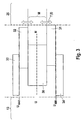
- FIG. 1 shows a first block diagram of an internal combustion engine and a device comprising a generator and a vehicle electrical system 1. Schematically represented are various functional modules and the functional relationships between these functional modules.
- reference numeral 10 is a Internal combustion engine, designated by reference numeral 11 an electronic engine control associated with this engine.
- Reference numeral 12 denotes an electric generator comprising an electric machine 12A and a regulator 12B.
- the electrical machine 12A is driven by the internal combustion engine 10 and converts the mechanical energy generated by the internal combustion engine 10 into the electrical energy required for an electrical system.
- the electrical system shown only schematically is designated by reference numeral 13.
- the system 1 comprises a functional module battery management, which bears the reference numeral 14.
- the electrical system 13 and the generator 12 are linked via the load current I_Last.
- the internal combustion engine 10 and the generator 12 are linked to one another via the variables torque M and rotational speed n, as well as their time changes dM / dt or dn / dt.
- the solution according to the invention now provides a possibility, during operation of the system 1 described above, to adapt the regulating speed of the voltage to the actual speed of the torque supply
- FIG. 2 shows a second block diagram in which various functional modules for the control of the generator 12 and their interaction are shown schematically.
- the generator 12 includes the electric machine 12A and a regulator 12B.
- Reference numeral 13 is a functional module representing the electrical system.
- the functional module 20 represents the drive train of the vehicle.
- Reference numeral 21 designates at least one control unit which coordinates the functional sequences in the control of the generator 12.
- arrows and double arrows are the functional links suggested that exist between the individual modules and functional modules.
- the essence of the invention is to provide an electrical device with a generator in which an extremely flexible control of the generator is made possible to ensure the highest possible voltage stability and high reliability.
- various control ranges are provided according to the invention, which enable an optimal control strategy. This is based on FIG. 3 which shows a third block diagram with representation of control areas.
- This control area (area 30) is adjoined by a control area (areas 31, 32) in which the generator 12 can not compensate for occurring load and voltage changes with the available, predefinable excess torque M_excess, but the occurring voltage deviation is still within a permissible voltage range.
- the permissible voltage range is determined by the predefinable limit values U_H and U_L.
- a third control area areas 33, 34
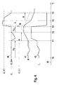
- FIG. 4 shows in a diagram various curves on the basis of which the operation of the electrical device 1 is explained below.
- Over a time axis 43 are Plotted curves that represent certain quantities as a function of time T.
- the load current I_Last is shown as a function of time T.
- the moment M is shown as a function of time T.
- the generator voltage U_Gen is shown as a function of time T.
- special voltage values are emphasized in the region of the curve representing the generator voltage, namely a desired value U_Soll, a minimum value U_L and a maximum value U_H. In this case, the setpoint U_Soll lies between the specified extreme values U_H and U_L.
- the time interval between a time T0 and a time T1 is considered.
- the curve 42 shows that the load current I_Last has a certain level and fluctuates within only comparatively narrow limits, which indicates a substantially constant load of the vehicle electrical system 13.
- the curve 40 representing the generator voltage U_Gen shows that the generator voltage U_Gen is essentially constant, which is regulated to its setpoint U_Soll in the considered time interval TO-T1.
- the curve 41 representing the moment M shows relatively small fluctuations in the torque M, since even small moment changes are sufficient to compensate for the fluctuations in the load current I_load.
- the interval T0-T1 thus corresponds to the above-mentioned first range of regulation in which a voltage regulation takes place in the immediate vicinity of the setpoint voltage U_setpoint and in which changes of the moment M are permitted up to a predefinable excess momentum.
- the load current I_Last at time T1 rises sharply because an electrical consumer has been switched on with a high power consumption and the on-board network 13 charged.
- this heavy load results in a voltage dip.
- the generator voltage drops below the setpoint voltage U_Soll and approaches the lower limit U_L.
- the invention makes it possible to adapt extremely flexibly to difficult operating situations, on the one hand to compensate for load changes as quickly as possible and thereby to ensure the highest possible voltage constancy.
- a high reliability of the electrical system and the greatest possible protection of voltage-sensitive components are achieved.
- different strategies can be used for the regulation of the moment in the range of torque control.
- the moment M increase linearly, wherein the increase with different slopes can be realized.
- a more complex, non-linear dependency can be provided for the rise of the moment M, whereby even dynamic adaptations to the respective situation are possible in order to achieve an optimum result.
- a functional dependency of the moment of influencing variables can also be realized by a corresponding characteristic field K, in which a specific value of the moment M is assigned to corresponding values of one or more influencing variables.
- the load current I_Last falls sharply at time T3.
- a powerful electrical load was switched off from the electrical system 13. It can be seen from the course of the curve 40 that, as a result, the generator voltage U_Gen rises sharply and even exceeds the maximum value U_H.
- the values U_set, U_H, U_L, as well as the boundaries between the two types of control torque control and voltage control and the width of the areas in which the respective control mode dominates can be specified application-specific.
Landscapes
- Engineering & Computer Science (AREA)
- Power Engineering (AREA)
- Control Of Eletrric Generators (AREA)
- Hybrid Electric Vehicles (AREA)
- Electric Propulsion And Braking For Vehicles (AREA)
- Control Of Electric Motors In General (AREA)
- Electrical Discharge Machining, Electrochemical Machining, And Combined Machining (AREA)
- Surgical Instruments (AREA)
- Control Of Charge By Means Of Generators (AREA)
Claims (14)
- Système électrique doté d'un générateur, en particulier destiné à être utilisé dans le réseau de bord d'un véhicule automobile, et présentant un régulateur qui régule la tension du générateur, une plage de la tension du réseau de bord dans laquelle une régulation de tension (plage 30) est exécutée et des plages (31, 32) dans lesquelles une régulation du couple du générateur est exécutée étant prévues pour la régulation,
caractérisé en ce que
la plage (30) destinée à la régulation de tension s'étend sur une distance prédéterminée autour de la tension de consigne (U_Soll). - Système électrique selon la revendication 1, caractérisé en ce que la transition entre les plages (30, 31, 32) et/ou la largeur des plages (30, 31, 32) dépendent de grandeurs caractéristiques du fonctionnement du dispositif.
- Système électrique selon l'une des revendications précédentes, caractérisé en ce que la plage (30) dépend d'un couple prédéterminé (couple excessif M_Überschuss).
- Système électrique selon l'une des revendications précédentes, caractérisé en ce que les plages (31, 32) de régulation du couple s'étendent des deux côtés de la plage (30) de régulation de tension.
- Système électrique selon l'une des revendications précédentes, caractérisé en ce que les plages (31, 32) de régulation du couple s'étendent à l'intérieur d'une plage de tension délimitée par les valeurs limites de tension (U_H, U_L).
- Système électrique selon l'une des revendications précédentes, caractérisé en ce que dans une plage (31, 32) de régulation du couple, le couple (M) peut être modifié suivant une fonction linéaire.
- Système électrique selon l'une des revendications précédentes, caractérisé en ce que dans une plage (31, 32) de régulation de couple, le couple (M) peut être modifié selon une fonction F = F(T, P) prédéterminée de manière quelconque, dans laquelle T représente le temps et P un paramètre de fonctionnement du dispositif.
- Système électrique selon l'une des revendications précédentes, caractérisé en ce que dans une plage (31, 32) de régulation du couple, le couple (M) peut être modifié selon une dépendance fonctionnelle définie dans un champ de caractéristiques (K).
- Procédé de conduite d'un système électrique qui comprend un générateur (12) doté d'un régulateur (12B), en particulier relié au réseau de bord (13) d'un véhicule automobile, dans lequel la tension du réseau de bord (13) ou la tension du générateur (U_Gen) sont détectées, le procédé vérifiant si la tension détectée est située dans une plage prédéterminée pour la régulation de tension autour de la tension de consigne (U_Soll), une régulation de la tension à la tension de consigne (U_Soll) étant exécutée lorsque la tension détectée est située dans la plage prédéterminée autour de la tension de consigne (U_Soll) et une- régulation du couple (M) du générateur étant exécutée,
caractérisé en ce que
la régulation du couple (M) du générateur est exécutée lorsque la tension détectée est située à l'extérieur de la plage prédéterminée autour de la tension de consigne mais encore à l'intérieur d'une plage de tension définie par des valeurs limites de tension (U_H, U_L) et
en ce que la priorité la plus élevée est attribuée à la régulation de tension lorsque la tension détectée est située à l'extérieur de la plage de tension délimitée par les valeurs limites de tension (U_H, U L). - Procédé selon la revendication 9, caractérisé en ce que lors de la régulation du couple (M), le couple est modifié selon une fonction linéaire.
- Procédé selon la revendication 9, caractérisé en ce que dans la régulation du couple (M), le couple est modifié selon une fonction quelconque F = F(T, P) dans laquelle T représente le temps et P un paramètre de fonctionnement prédéterminé du dispositif.
- Procédé selon la revendication 9, caractérisé en ce que dans la régulation du couple (M), le couple est modifié selon une dépendance fonctionnelle définie dans un champ de caractéristiques (K).
- Procédé selon l'une des revendications 9 à 12, caractérisé en ce que la largeur des plages (30, 31, 32) dans lesquelles une régulation de la tension ou une régulation du couple sont exécutées et/ou les emplacements de transition entre lesdites plages sont prédéterminés par l'application à laquelle le dispositif est destiné.
- Procédé selon l'une des revendications 9 à 12, caractérisé en ce que la largeur des plages (30, 31, 32) dans lesquelles une régulation de tension ou une régulation du couple sont exécutées et/ou les emplacements de transition entre lesdites plages pendant que le véhicule équipé du dispositif roule sont adaptés à des paramètres de fonctionnement du dispositif.
Applications Claiming Priority (2)
| Application Number | Priority Date | Filing Date | Title |
|---|---|---|---|
| DE10361215A DE10361215A1 (de) | 2003-12-24 | 2003-12-24 | Elektrische Einrichtung und Betriebsverfahren |
| PCT/DE2004/002681 WO2005062441A1 (fr) | 2003-12-24 | 2004-12-07 | Dispositif electrique et procede de fonctionnement |
Publications (2)
| Publication Number | Publication Date |
|---|---|
| EP1700367A1 EP1700367A1 (fr) | 2006-09-13 |
| EP1700367B1 true EP1700367B1 (fr) | 2010-02-24 |
Family
ID=34706571
Family Applications (1)
| Application Number | Title | Priority Date | Filing Date |
|---|---|---|---|
| EP04802889A Expired - Lifetime EP1700367B1 (fr) | 2003-12-24 | 2004-12-07 | Dispositif electrique et procede de fonctionnement |
Country Status (6)
| Country | Link |
|---|---|
| US (1) | US8022677B2 (fr) |
| EP (1) | EP1700367B1 (fr) |
| JP (1) | JP2007517487A (fr) |
| AT (1) | ATE459121T1 (fr) |
| DE (2) | DE10361215A1 (fr) |
| WO (1) | WO2005062441A1 (fr) |
Families Citing this family (12)
| Publication number | Priority date | Publication date | Assignee | Title |
|---|---|---|---|---|
| JP4491839B2 (ja) * | 2005-09-07 | 2010-06-30 | 株式会社デンソー | 発電機制御装置 |
| JP2008189090A (ja) * | 2007-02-02 | 2008-08-21 | Denso Corp | 車両用制御装置 |
| US7944598B2 (en) * | 2008-11-06 | 2011-05-17 | Corning Incorporated | Speckle mitigation in laser scanner projector systems |
| DE102010029967B4 (de) * | 2010-06-11 | 2025-11-06 | Seg Automotive Germany Gmbh | Verfahren und Vorrichtung zum Ausgleich eines Einbruchs der Ausgangsspannung eines Kraftfahrzeuggenerators |
| DE102010040863A1 (de) | 2010-09-16 | 2012-03-22 | Robert Bosch Gmbh | Verfahren und Vorrichtung zum Betreiben eines Generators in einem Rekuperationssystem eines Kraftfahrzeuges |
| DE102010043095A1 (de) | 2010-10-29 | 2012-05-03 | Robert Bosch Gmbh | Verfahren zur Reduzierung einer Spannungswelligkeit aufgrund Drehungleichförmigkeit eines von einer Brennkraftmaschine angetriebenen Generators |
| DE102011088314A1 (de) | 2011-12-12 | 2013-06-13 | Bayerische Motoren Werke Aktiengesellschaft | Hochfahren des Erregerstroms eines an ein Bordnetz eines Kraftfahrzeugs angeschlossenen Mehrphasenwechselstrom-Generators beim Aktivieren des Generators |
| DE102012205120A1 (de) * | 2012-03-29 | 2013-10-02 | Bayerische Motoren Werke Aktiengesellschaft | Verfahren zur Regelung eines Energiewandlers in einem Kraftfahrzeug |
| DE102012223516A1 (de) | 2012-12-18 | 2014-03-13 | Robert Bosch Gmbh | Generatorregler zur Berechnung von Systemgrößen |
| DE102013207135A1 (de) * | 2013-04-19 | 2014-10-23 | Bayerische Motoren Werke Aktiengesellschaft | Hochfahren des Erregerstroms eines an ein Bordnetz eines Kraftfahrzeugs angeschlossenen Mehrphasenwechselstrom-Generators beim Aktivieren des Generators |
| US9577558B2 (en) * | 2014-07-03 | 2017-02-21 | Caterpillar Inc. | Power management system having automatic calibration |
| DE102017201687A1 (de) | 2017-02-02 | 2018-08-02 | Siemens Aktiengesellschaft | Regelbare Spannungserzeugungsvorrichtung und Verfahren zum Betreiben einer regelbaren Spannungserzeugungsvorrichtung |
Family Cites Families (67)
| Publication number | Priority date | Publication date | Assignee | Title |
|---|---|---|---|---|
| US3183422A (en) * | 1963-02-18 | 1965-05-11 | Westinghouse Electric Corp | Generator fed plural motor system including voltage control, current control and slip control |
| AU4752068A (en) * | 1968-12-09 | 1970-06-18 | Central Electricity Generating Board | Improvements inthe control of electrical machines |
| US4012680A (en) * | 1975-02-27 | 1977-03-15 | General Electric Company | Field boost arrangement for separately excited D-C traction motors of a vehicle propulsion system |
| US4012677A (en) * | 1975-02-27 | 1977-03-15 | General Electric Company | Speed control for electrically propelled traction vehicles |
| US3970858A (en) * | 1975-02-27 | 1976-07-20 | General Electric Company | Prime mover speed responsive load control for electrically propelled traction vehicles |
| US4017739A (en) * | 1975-02-27 | 1977-04-12 | General Electric Company | Lifting force responsive load control for electrically propelled earthmoving vehicles |
| JPS56101151U (fr) * | 1979-12-29 | 1981-08-08 | ||
| US4629968A (en) * | 1985-08-23 | 1986-12-16 | General Motors Corporation | Alternator load control system |
| US4636706A (en) * | 1985-09-12 | 1987-01-13 | General Motors Corporation | Generator voltage regulating system |
| JPS6364531A (ja) | 1986-09-05 | 1988-03-23 | 株式会社デンソー | 車両用充電発電機の電圧調整装置 |
| US4931715A (en) * | 1986-11-03 | 1990-06-05 | Teledyne Inet | Synchronous motor torque control device |
| US4982567A (en) * | 1988-01-29 | 1991-01-08 | Mazda Motor Corporation | Air supply control systems for turbocharged internal combustion engines |
| JP2751174B2 (ja) | 1988-02-01 | 1998-05-18 | 株式会社デンソー | 車両の充電制御装置 |
| JPH01218333A (ja) * | 1988-02-24 | 1989-08-31 | Mitsubishi Electric Corp | 車両用交流発電機の制御装置 |
| EP0334228B1 (fr) * | 1988-03-19 | 1993-10-27 | Mazda Motor Corporation | Systèmes de commande d'alimentation d'air de moteurs à combustion interne |
| DE68901795T2 (de) * | 1988-03-19 | 1993-01-21 | Mazda Motor | Zufuhrluftkontrollverfahren fuer brennkraftmaschinen. |
| US5003781A (en) * | 1988-05-23 | 1991-04-02 | Mazda Motor Corporation | Air supply and exhaust control systems for turbocharged internal combustion engines |
| JP2751208B2 (ja) * | 1988-06-03 | 1998-05-18 | 株式会社デンソー | 車両用発電制御装置 |
| JPH0739813B2 (ja) * | 1988-10-15 | 1995-05-01 | マツダ株式会社 | 排気ターボ過給機付エンジンの制御装置 |
| JPH0647933B2 (ja) * | 1988-10-27 | 1994-06-22 | マツダ株式会社 | 過給機付エンジンの制御装置 |
| JPH02238143A (ja) * | 1989-03-09 | 1990-09-20 | Mazda Motor Corp | 過給機付エンジンの燃料制御装置 |
| JP2576233B2 (ja) * | 1989-07-13 | 1997-01-29 | 三菱電機株式会社 | 車両用交流発電機の制御装置 |
| DE4009285A1 (de) * | 1989-08-23 | 1990-12-20 | Audi Ag | Verfahren zur zylinderselektiven ueberwachung des energieumsatzes bei einer mehrzylinder-brennkraftmaschine |
| US5153498A (en) * | 1989-11-07 | 1992-10-06 | Sundstrand Corporation | Generic control unit |
| US5225764A (en) * | 1991-11-29 | 1993-07-06 | Sgs-Thomson Microelectronics, Inc. | Voltage regulating circuitry to vary the alternator field coil drive at a rate dependent upon a rotor velocity signal |
| JP3180436B2 (ja) * | 1992-05-14 | 2001-06-25 | 株式会社デンソー | 発電機の励磁電流制御装置 |
| US5376877A (en) * | 1992-06-11 | 1994-12-27 | Generac Corporation | Engine-driven generator |
| US5373196A (en) * | 1992-10-16 | 1994-12-13 | Vanner Weldon Inc. | Combination static/dynamic inverter |
| EP0674381B1 (fr) * | 1994-03-23 | 1999-06-16 | ABB Daimler-Benz Transportation (Technology) GmbH | Procédé de régulation du couple d'une machine asynchrone |
| JPH08126223A (ja) * | 1994-10-26 | 1996-05-17 | Mitsubishi Electric Corp | 交流発電機の制御装置 |
| US5668721A (en) * | 1995-10-02 | 1997-09-16 | General Motors Corporation | Electric power steering motor control |
| JP3511760B2 (ja) * | 1995-10-09 | 2004-03-29 | マツダ株式会社 | オルタネーターの制御装置 |
| US6097127A (en) * | 1996-08-22 | 2000-08-01 | Rivera; Nicholas N. | Permanent magnet direct current (PMDC) machine with integral reconfigurable winding control |
| PT947042E (pt) * | 1996-12-20 | 2002-04-29 | Manuel Dos Santos Da Ponte | Aparelho gerador hibrido |
| DE19733221A1 (de) * | 1997-08-01 | 1999-02-04 | Bosch Gmbh Robert | Verfahren zur Regelung eines Generators |
| KR100376920B1 (ko) * | 1998-01-27 | 2003-03-26 | 미쓰비시덴키 가부시키가이샤 | 차량용 교류발전기의 제어장치 |
| DE19903426A1 (de) | 1999-01-29 | 2000-08-03 | Bosch Gmbh Robert | Vorrichung und Verfahren zur Regelung eines Generators mit zugeordnetem Spannungswandler |
| US6888280B2 (en) * | 1999-04-01 | 2005-05-03 | Jean-Yves Dubé | High performance brushless motor and drive for an electrical vehicle motorization |
| JP2001069798A (ja) * | 1999-08-30 | 2001-03-16 | Mitsubishi Electric Corp | 交流発電機の制御装置 |
| JP3509690B2 (ja) | 1999-12-24 | 2004-03-22 | 株式会社デンソー | 車両用交流発電機、車両用交流発電機の制御装置及び車両用交流発電機の制御方法 |
| US6653744B2 (en) * | 2000-08-01 | 2003-11-25 | Clipper Wind Technology, Inc. | Distributed generation drivetrain (DGD) controller for application to wind turbine and ocean current turbine generators |
| US6555993B2 (en) * | 2000-09-28 | 2003-04-29 | Denso Corporation | Voltage regulating system of a vehicle AC generator for charging a battery |
| JP4193348B2 (ja) * | 2000-10-03 | 2008-12-10 | 株式会社デンソー | 車両用発電制御装置 |
| US6469476B1 (en) * | 2000-10-17 | 2002-10-22 | Delphi Technologies, Inc. | Multi-mode converter for a motor vehicle electrical system |
| JP3797201B2 (ja) * | 2001-04-25 | 2006-07-12 | 株式会社デンソー | 車両用発電制御装置 |
| JP3921999B2 (ja) * | 2001-11-08 | 2007-05-30 | 株式会社デンソー | 車両用交流発電機の発電制御装置、その製造方法およびその調整方法、ならびに発電制御方法 |
| JP3982247B2 (ja) | 2001-12-06 | 2007-09-26 | 株式会社デンソー | 車両用発電機の制御装置 |
| DE10309326B4 (de) | 2002-03-16 | 2007-08-30 | Bayerische Motoren Werke Ag | Verfahren und Vorrichtung zur Steuerung eines Drehstromgenerators bei einem Kraftfahrzeug |
| KR100456851B1 (ko) * | 2002-07-31 | 2004-11-10 | 현대자동차주식회사 | 직렬형 하이브리드 차량의 보조 동력 제어장치 |
| US7106028B2 (en) * | 2002-11-26 | 2006-09-12 | Mitsubishi Denki Kabushiki Kaisha | Controller of A.C. generator for vehicles |
| JP4103608B2 (ja) * | 2003-01-29 | 2008-06-18 | 株式会社デンソー | 車両用発電機のトルク演算装置 |
| US6876177B2 (en) * | 2003-02-04 | 2005-04-05 | General Motors Corporation | Load dump transient voltage controller |
| DE10324948A1 (de) | 2003-06-03 | 2004-12-23 | Daimlerchrysler Ag | Kraftfahrzeug-Antriebsvorrichtung |
| JP3997987B2 (ja) * | 2003-12-25 | 2007-10-24 | 株式会社デンソー | 発電制御システム |
| TWI342663B (en) * | 2004-02-25 | 2011-05-21 | Rohm Co Ltd | Phase adjustment circuit, motor driving control circuit, and motor apparatus |
| FI118027B (fi) * | 2004-08-11 | 2007-05-31 | Abb Oy | Menetelmä tuulivoimalan yhteydessä |
| US7009365B1 (en) * | 2004-08-31 | 2006-03-07 | General Motors Corporation | Systems and methods for control of vehicle electrical generator |
| US7116067B2 (en) * | 2004-09-21 | 2006-10-03 | Honeywell International Inc. | Power converter controlling apparatus and method providing ride through capability during power interruption in a motor drive system |
| US7348756B2 (en) * | 2004-11-30 | 2008-03-25 | Honeywell International Inc. | Advanced current control method and apparatus for a motor drive system |
| JP4179296B2 (ja) * | 2005-03-01 | 2008-11-12 | 株式会社デンソー | 発電制御装置 |
| JP4737195B2 (ja) * | 2005-03-09 | 2011-07-27 | トヨタ自動車株式会社 | 負荷駆動装置、車両、および負荷駆動装置における異常処理方法 |
| JP4549923B2 (ja) * | 2005-05-20 | 2010-09-22 | トヨタ自動車株式会社 | 負荷駆動装置およびそれを搭載した電動車両 |
| JP2007089358A (ja) * | 2005-09-26 | 2007-04-05 | Mitsubishi Electric Corp | 車両用交流発電機の制御装置 |
| JP4449882B2 (ja) * | 2005-10-14 | 2010-04-14 | 株式会社デンソー | 車両用発電制御装置 |
| JP5186690B2 (ja) * | 2008-03-21 | 2013-04-17 | 株式会社小松製作所 | ハイブリッド建設機械における蓄電装置の劣化状態判定方法および装置 |
| JP4644722B2 (ja) * | 2008-03-31 | 2011-03-02 | 日立建機株式会社 | 電気駆動車両 |
| JP4984331B2 (ja) * | 2008-05-09 | 2012-07-25 | 株式会社デンソー | 電気自動車の制御装置 |
-
2003
- 2003-12-24 DE DE10361215A patent/DE10361215A1/de not_active Ceased
-
2004
- 2004-12-07 DE DE502004010820T patent/DE502004010820D1/de not_active Expired - Lifetime
- 2004-12-07 AT AT04802889T patent/ATE459121T1/de not_active IP Right Cessation
- 2004-12-07 US US10/582,926 patent/US8022677B2/en not_active Expired - Lifetime
- 2004-12-07 EP EP04802889A patent/EP1700367B1/fr not_active Expired - Lifetime
- 2004-12-07 JP JP2006545905A patent/JP2007517487A/ja active Pending
- 2004-12-07 WO PCT/DE2004/002681 patent/WO2005062441A1/fr not_active Ceased
Also Published As
| Publication number | Publication date |
|---|---|
| JP2007517487A (ja) | 2007-06-28 |
| DE10361215A1 (de) | 2005-07-28 |
| US8022677B2 (en) | 2011-09-20 |
| WO2005062441A1 (fr) | 2005-07-07 |
| EP1700367A1 (fr) | 2006-09-13 |
| US20070252560A1 (en) | 2007-11-01 |
| ATE459121T1 (de) | 2010-03-15 |
| DE502004010820D1 (de) | 2010-04-08 |
Similar Documents
| Publication | Publication Date | Title |
|---|---|---|
| DE69626771T2 (de) | Verfahren und Vorrichtung zur Regelung der elektrischen Energieverteilung in einem Kraftfahrzeug, insbesondere mit Hybridantrieb | |
| EP1525113B1 (fr) | Procede et systeme pour commander l'alimentation en energie d'un dispositif mobile presentant au moins un moteur d'entrainement electrique et un systeme d'energie hybride contenant un systeme de pile a combustible et un systeme d'energie dynamique | |
| DE112009001196B4 (de) | Energieversorgungseinrichtung für ein Fahrzeug sowie Verfahren zum Steuern einer Energieversorgungseinrichtung für ein Fahrzeug | |
| EP1700367B1 (fr) | Dispositif electrique et procede de fonctionnement | |
| DE102011083010A1 (de) | Steuervorrichtung für einen Gleichspannungswandler eines elektrischen Antriebssystems und Verfahren zum Betreiben eines Gleichspannungswandlers | |
| EP3019377B1 (fr) | Système de commande et procédé permettant de faire fonctionner un véhicule automobile | |
| EP4263267A1 (fr) | Appareil d'entraînement électrique pour véhicule et procédé d'actionnement d'un appareil d'entraînement électrique pour véhicule | |
| DE102006001201A1 (de) | Verfahren zur Steuerung eines Batterieladungsvorgangs | |
| DE102011012476B4 (de) | Verfahren zur Stabilisierung eines offenen Zwischenkreisspannungsnetzes mit mehreren Teilnehmern | |
| DE10234088A1 (de) | Verfahren zur spannungs- und fahrdynamikabhängigen Regelung eines Generators | |
| EP1386789B1 (fr) | Dispositif et méthode de régulation d'un réseau de distribution automobile | |
| EP1031182A2 (fr) | Procede et circuit pour la production d'un signal de reglage a modulation d'impulsions en largeur pour un actionneur a courant continu | |
| EP1826054A2 (fr) | Procédé et dispositif destinés au réglage d'un système d'entraînement hydraulique | |
| EP1201504B1 (fr) | Méthode pour la régulation de la distribution d'énergie pour des équipements électriques dans un véhicule automobile | |
| DE102013226801A1 (de) | Arbeitspunktsteuerung zum wirkungsgradoptimierten Betrieb von Asynchronmaschinen | |
| DE102017213017A1 (de) | Verfahren zum Betrieb eines Bordnetzes mit mehreren Bordnetzzweigen und Fahrzeugbordnetz | |
| DE102008041027A1 (de) | Bordelektriksystem für ein Kraftfahrzeug | |
| DE102021125143A1 (de) | Vorrichtung und Verfahren zur Energieversorgung eines seillosen Aufzugsystems mit Linearantrieb sowie Verwendung | |
| DE102004057100A1 (de) | Antriebsvorrichtung und Regelungsverfahren für ein elektrisch angetriebenes Fahrzeug | |
| AT509441B1 (de) | Regelung von zwei generatoren eines kraftfahrzeug-stromkreises | |
| EP1094588B1 (fr) | Circuit de mise en oeuvre d'un moteur électrique | |
| EP1775822B1 (fr) | Procédé et dispositif pour élever la tension réglée d'un générateur dans un véhicule | |
| DE102020214498A1 (de) | Fahrzeug und Verfahren zu dessen Betrieb | |
| DE102024202897A1 (de) | Verfahren und Recheneinheit zum Steuern eines Gleichspannungssystems | |
| DE102020214496A1 (de) | Fahrzeug und Verfahren zu dessen Betrieb |
Legal Events
| Date | Code | Title | Description |
|---|---|---|---|
| PUAI | Public reference made under article 153(3) epc to a published international application that has entered the european phase |
Free format text: ORIGINAL CODE: 0009012 |
|
| 17P | Request for examination filed |
Effective date: 20060724 |
|
| AK | Designated contracting states |
Kind code of ref document: A1 Designated state(s): AT BE BG CH CY CZ DE DK EE ES FI FR GB GR HU IE IS IT LI LT LU MC NL PL PT RO SE SI SK TR |
|
| DAX | Request for extension of the european patent (deleted) | ||
| RAP1 | Party data changed (applicant data changed or rights of an application transferred) |
Owner name: BMW AG Owner name: ROBERT BOSCH GMBH Owner name: DAIMLERCHRYSLER AG |
|
| 17Q | First examination report despatched |
Effective date: 20070904 |
|
| RAP1 | Party data changed (applicant data changed or rights of an application transferred) |
Owner name: DAIMLER AG Owner name: ROBERT BOSCH GMBH Owner name: BMW AG |
|
| GRAP | Despatch of communication of intention to grant a patent |
Free format text: ORIGINAL CODE: EPIDOSNIGR1 |
|
| GRAS | Grant fee paid |
Free format text: ORIGINAL CODE: EPIDOSNIGR3 |
|
| GRAA | (expected) grant |
Free format text: ORIGINAL CODE: 0009210 |
|
| AK | Designated contracting states |
Kind code of ref document: B1 Designated state(s): AT BE BG CH CY CZ DE DK EE ES FI FR GB GR HU IE IS IT LI LT LU MC NL PL PT RO SE SI SK TR |
|
| REG | Reference to a national code |
Ref country code: GB Ref legal event code: FG4D Free format text: NOT ENGLISH |
|
| REG | Reference to a national code |
Ref country code: CH Ref legal event code: EP |
|
| REG | Reference to a national code |
Ref country code: IE Ref legal event code: FG4D Free format text: LANGUAGE OF EP DOCUMENT: GERMAN |
|
| REF | Corresponds to: |
Ref document number: 502004010820 Country of ref document: DE Date of ref document: 20100408 Kind code of ref document: P |
|
| REG | Reference to a national code |
Ref country code: NL Ref legal event code: VDEP Effective date: 20100224 |
|
| LTIE | Lt: invalidation of european patent or patent extension |
Effective date: 20100224 |
|
| PG25 | Lapsed in a contracting state [announced via postgrant information from national office to epo] |
Ref country code: LT Free format text: LAPSE BECAUSE OF FAILURE TO SUBMIT A TRANSLATION OF THE DESCRIPTION OR TO PAY THE FEE WITHIN THE PRESCRIBED TIME-LIMIT Effective date: 20100224 Ref country code: IS Free format text: LAPSE BECAUSE OF FAILURE TO SUBMIT A TRANSLATION OF THE DESCRIPTION OR TO PAY THE FEE WITHIN THE PRESCRIBED TIME-LIMIT Effective date: 20100624 Ref country code: PT Free format text: LAPSE BECAUSE OF FAILURE TO SUBMIT A TRANSLATION OF THE DESCRIPTION OR TO PAY THE FEE WITHIN THE PRESCRIBED TIME-LIMIT Effective date: 20100625 |
|
| PG25 | Lapsed in a contracting state [announced via postgrant information from national office to epo] |
Ref country code: FI Free format text: LAPSE BECAUSE OF FAILURE TO SUBMIT A TRANSLATION OF THE DESCRIPTION OR TO PAY THE FEE WITHIN THE PRESCRIBED TIME-LIMIT Effective date: 20100224 Ref country code: SI Free format text: LAPSE BECAUSE OF FAILURE TO SUBMIT A TRANSLATION OF THE DESCRIPTION OR TO PAY THE FEE WITHIN THE PRESCRIBED TIME-LIMIT Effective date: 20100224 Ref country code: PL Free format text: LAPSE BECAUSE OF FAILURE TO SUBMIT A TRANSLATION OF THE DESCRIPTION OR TO PAY THE FEE WITHIN THE PRESCRIBED TIME-LIMIT Effective date: 20100224 |
|
| REG | Reference to a national code |
Ref country code: IE Ref legal event code: FD4D |
|
| PG25 | Lapsed in a contracting state [announced via postgrant information from national office to epo] |
Ref country code: GR Free format text: LAPSE BECAUSE OF FAILURE TO SUBMIT A TRANSLATION OF THE DESCRIPTION OR TO PAY THE FEE WITHIN THE PRESCRIBED TIME-LIMIT Effective date: 20100525 Ref country code: CY Free format text: LAPSE BECAUSE OF FAILURE TO SUBMIT A TRANSLATION OF THE DESCRIPTION OR TO PAY THE FEE WITHIN THE PRESCRIBED TIME-LIMIT Effective date: 20100224 Ref country code: ES Free format text: LAPSE BECAUSE OF FAILURE TO SUBMIT A TRANSLATION OF THE DESCRIPTION OR TO PAY THE FEE WITHIN THE PRESCRIBED TIME-LIMIT Effective date: 20100604 Ref country code: IE Free format text: LAPSE BECAUSE OF FAILURE TO SUBMIT A TRANSLATION OF THE DESCRIPTION OR TO PAY THE FEE WITHIN THE PRESCRIBED TIME-LIMIT Effective date: 20100224 Ref country code: NL Free format text: LAPSE BECAUSE OF FAILURE TO SUBMIT A TRANSLATION OF THE DESCRIPTION OR TO PAY THE FEE WITHIN THE PRESCRIBED TIME-LIMIT Effective date: 20100224 Ref country code: RO Free format text: LAPSE BECAUSE OF FAILURE TO SUBMIT A TRANSLATION OF THE DESCRIPTION OR TO PAY THE FEE WITHIN THE PRESCRIBED TIME-LIMIT Effective date: 20100224 Ref country code: SE Free format text: LAPSE BECAUSE OF FAILURE TO SUBMIT A TRANSLATION OF THE DESCRIPTION OR TO PAY THE FEE WITHIN THE PRESCRIBED TIME-LIMIT Effective date: 20100224 Ref country code: EE Free format text: LAPSE BECAUSE OF FAILURE TO SUBMIT A TRANSLATION OF THE DESCRIPTION OR TO PAY THE FEE WITHIN THE PRESCRIBED TIME-LIMIT Effective date: 20100224 |
|
| PG25 | Lapsed in a contracting state [announced via postgrant information from national office to epo] |
Ref country code: CZ Free format text: LAPSE BECAUSE OF FAILURE TO SUBMIT A TRANSLATION OF THE DESCRIPTION OR TO PAY THE FEE WITHIN THE PRESCRIBED TIME-LIMIT Effective date: 20100224 Ref country code: BG Free format text: LAPSE BECAUSE OF FAILURE TO SUBMIT A TRANSLATION OF THE DESCRIPTION OR TO PAY THE FEE WITHIN THE PRESCRIBED TIME-LIMIT Effective date: 20100524 Ref country code: SK Free format text: LAPSE BECAUSE OF FAILURE TO SUBMIT A TRANSLATION OF THE DESCRIPTION OR TO PAY THE FEE WITHIN THE PRESCRIBED TIME-LIMIT Effective date: 20100224 |
|
| PLBE | No opposition filed within time limit |
Free format text: ORIGINAL CODE: 0009261 |
|
| STAA | Information on the status of an ep patent application or granted ep patent |
Free format text: STATUS: NO OPPOSITION FILED WITHIN TIME LIMIT |
|
| PG25 | Lapsed in a contracting state [announced via postgrant information from national office to epo] |
Ref country code: DK Free format text: LAPSE BECAUSE OF FAILURE TO SUBMIT A TRANSLATION OF THE DESCRIPTION OR TO PAY THE FEE WITHIN THE PRESCRIBED TIME-LIMIT Effective date: 20100224 |
|
| 26N | No opposition filed |
Effective date: 20101125 |
|
| BERE | Be: lapsed |
Owner name: DAIMLER A.G. Effective date: 20101231 Owner name: BMW A.G. Effective date: 20101231 Owner name: ROBERT BOSCH G.M.B.H. Effective date: 20101231 |
|
| PG25 | Lapsed in a contracting state [announced via postgrant information from national office to epo] |
Ref country code: MC Free format text: LAPSE BECAUSE OF NON-PAYMENT OF DUE FEES Effective date: 20101231 |
|
| REG | Reference to a national code |
Ref country code: CH Ref legal event code: PL |
|
| PG25 | Lapsed in a contracting state [announced via postgrant information from national office to epo] |
Ref country code: BE Free format text: LAPSE BECAUSE OF NON-PAYMENT OF DUE FEES Effective date: 20101231 |
|
| PG25 | Lapsed in a contracting state [announced via postgrant information from national office to epo] |
Ref country code: LI Free format text: LAPSE BECAUSE OF NON-PAYMENT OF DUE FEES Effective date: 20101231 Ref country code: CH Free format text: LAPSE BECAUSE OF NON-PAYMENT OF DUE FEES Effective date: 20101231 |
|
| PG25 | Lapsed in a contracting state [announced via postgrant information from national office to epo] |
Ref country code: AT Free format text: LAPSE BECAUSE OF NON-PAYMENT OF DUE FEES Effective date: 20101207 |
|
| REG | Reference to a national code |
Ref country code: AT Ref legal event code: MM01 Ref document number: 459121 Country of ref document: AT Kind code of ref document: T Effective date: 20101207 |
|
| PG25 | Lapsed in a contracting state [announced via postgrant information from national office to epo] |
Ref country code: LU Free format text: LAPSE BECAUSE OF NON-PAYMENT OF DUE FEES Effective date: 20101207 Ref country code: HU Free format text: LAPSE BECAUSE OF FAILURE TO SUBMIT A TRANSLATION OF THE DESCRIPTION OR TO PAY THE FEE WITHIN THE PRESCRIBED TIME-LIMIT Effective date: 20100825 |
|
| PG25 | Lapsed in a contracting state [announced via postgrant information from national office to epo] |
Ref country code: TR Free format text: LAPSE BECAUSE OF FAILURE TO SUBMIT A TRANSLATION OF THE DESCRIPTION OR TO PAY THE FEE WITHIN THE PRESCRIBED TIME-LIMIT Effective date: 20100224 |
|
| REG | Reference to a national code |
Ref country code: FR Ref legal event code: PLFP Year of fee payment: 12 |
|
| REG | Reference to a national code |
Ref country code: DE Ref legal event code: R081 Ref document number: 502004010820 Country of ref document: DE Owner name: ROBERT BOSCH GMBH, DE Free format text: FORMER OWNERS: BAYERISCHE MOTOREN WERKE AKTIENGESELLSCHAFT, 80809 MUENCHEN, DE; DAIMLER AG, 70327 STUTTGART, DE; ROBERT BOSCH GMBH, 70469 STUTTGART, DE |
|
| REG | Reference to a national code |
Ref country code: FR Ref legal event code: PLFP Year of fee payment: 13 |
|
| REG | Reference to a national code |
Ref country code: FR Ref legal event code: TP Owner name: ROBERT BOSCH GMBH, DE Effective date: 20170809 |
|
| REG | Reference to a national code |
Ref country code: GB Ref legal event code: 732E Free format text: REGISTERED BETWEEN 20171005 AND 20171011 |
|
| REG | Reference to a national code |
Ref country code: FR Ref legal event code: PLFP Year of fee payment: 14 |
|
| PGFP | Annual fee paid to national office [announced via postgrant information from national office to epo] |
Ref country code: GB Payment date: 20231220 Year of fee payment: 20 |
|
| PGFP | Annual fee paid to national office [announced via postgrant information from national office to epo] |
Ref country code: FR Payment date: 20231219 Year of fee payment: 20 |
|
| PGFP | Annual fee paid to national office [announced via postgrant information from national office to epo] |
Ref country code: DE Payment date: 20240227 Year of fee payment: 20 |
|
| PGFP | Annual fee paid to national office [announced via postgrant information from national office to epo] |
Ref country code: IT Payment date: 20231229 Year of fee payment: 20 |
|
| REG | Reference to a national code |
Ref country code: DE Ref legal event code: R071 Ref document number: 502004010820 Country of ref document: DE |
|
| REG | Reference to a national code |
Ref country code: GB Ref legal event code: PE20 Expiry date: 20241206 |
|
| PG25 | Lapsed in a contracting state [announced via postgrant information from national office to epo] |
Ref country code: GB Free format text: LAPSE BECAUSE OF EXPIRATION OF PROTECTION Effective date: 20241206 |
|
| PG25 | Lapsed in a contracting state [announced via postgrant information from national office to epo] |
Ref country code: GB Free format text: LAPSE BECAUSE OF EXPIRATION OF PROTECTION Effective date: 20241206 |