EP1700535A1 - Support pour parapluies ou similaire - Google Patents
Support pour parapluies ou similaire Download PDFInfo
- Publication number
- EP1700535A1 EP1700535A1 EP05005321A EP05005321A EP1700535A1 EP 1700535 A1 EP1700535 A1 EP 1700535A1 EP 05005321 A EP05005321 A EP 05005321A EP 05005321 A EP05005321 A EP 05005321A EP 1700535 A1 EP1700535 A1 EP 1700535A1
- Authority
- EP
- European Patent Office
- Prior art keywords
- mast
- tilting
- umbrella stand
- stand according
- rotary sleeve
- Prior art date
- Legal status (The legal status is an assumption and is not a legal conclusion. Google has not performed a legal analysis and makes no representation as to the accuracy of the status listed.)
- Withdrawn
Links
Images


Classifications
-
- A—HUMAN NECESSITIES
- A45—HAND OR TRAVELLING ARTICLES
- A45B—WALKING STICKS; UMBRELLAS; LADIES' OR LIKE FANS
- A45B17/00—Tiltable umbrellas
-
- A—HUMAN NECESSITIES
- A45—HAND OR TRAVELLING ARTICLES
- A45B—WALKING STICKS; UMBRELLAS; LADIES' OR LIKE FANS
- A45B23/00—Other umbrellas
- A45B2023/0031—Cantilever umbrellas or sunshades with a support arm
- A45B2023/0081—Cantilever umbrellas or sunshades with a support arm the support arm being rotatable about a horizontal axis for adjusting the position
Definitions
- the invention relates to an umbrella stand for umbrellas or the like according to the preamble of claim 1.
- Usual parasols with a screen diameter of up to 2 m are usually used with their mast in mast feet, either in the ground or z.
- Parasol has become known from DE-GM 87 03 822, which has a tilting joint which includes a sleeve-like sliding sleeve, which releases the joint for tilting the canopy after turning.
- the invention has for its object to provide an umbrella stand for umbrellas or the like, which allows a simple tilting movement of the parasol is störunan University and has an attractive appearance.
- the invention relates to a parasol stand for umbrellas or the like with a two-part tubular mast with a mast base and a mast top part holding the parasol, and a lockable tilting joint.
- the tilting joint has a tilting bolt anchored in one of the mast parts, which is received by means of a bolt directed radially to the mast between the legs of a U-shaped bolt bearing anchored in the other mast part.
- stop means provided to limit the pivotal movement of the tilting bolt about the bolt.
- the tilting joint is surrounded by a rotating sleeve, which prevents pivoting of the tilting joint in a first rotational position and releases it in a second rotational position.
- the umbrella stand according to the invention includes a tilting joint which is completely accommodated in the tubular mast.
- the actuation of the tilting joint is carried out by simply rotating the rotary sleeve in two positions, wherein in a first position of the rotary sleeve pivoting of the mast is blocked and is released in a second rotational position.
- the rotary sleeve is preferably located between the upper part of the mast and the lower part of the mast and is rotatably mounted on the essentially cylindrical pivot.
- the rotary sleeve is preferably rotatable by means of a latching arrangement in a plurality of locking positions, so that an unwanted rotation of the rotary sleeve is prevented.
- the tilting bolt of the rotary joint is preferably accommodated in a flange which forms a radial stop surface with respect to the pin bearing.
- the outer diameter of the flange substantially corresponds to the outer diameter of the mast.
- a first half of the end faces of the legs of the pin bearing extends at right angles to the mast axis, wherein in the 0 ° position of the mast shell relative to the mast lower part, the first half of the end faces abuts the stop surface of the flange.
- a second half of the end faces of the legs of the pin bearing extends at an oblique angle to the mast axis, wherein in the bent position of the mast top relative to the mast lower part, the second half of the end faces abuts the stop surface of the flange.
- the tilting bolt may also have a stop extension, which is pivotable between two stop surfaces of the pin bearing.
- the rotary sleeve preferably contains a first partial edge extending in the radial plane and a second partial edge extending at an oblique angle to the mast axis relative to the abutment surface of the flange, blocking pivoting of the upper mast upper part relative to the lower mast lower part by abutment of the partial edges against the abutment surfaces in the first rotational position of the rotary sleeve is and is released in a second rotational position.
- a pivoting of the mast is therefore only possible if the rotary sleeve is in such a position that the oblique part edge of the rotary sleeve allows pivoting of the tilting joint.
- the invention prevents an automatic pivoting of the tilting joint from the vertical position, as this is prevented by the rotary sleeve in a corresponding direction of rotation.
- the pivoted position In the released from the rotary sleeve pivot position of the mast shell, the pivoted position can be secured by a spring-loaded locking lug is used, by which the tilting pin is resiliently biased in the pivoting position.
- the return of the mast shell relative to the mast base can only be performed when the spring force of the latch is overcome. Another backup can thereby be achieved that in the pivoting position a locking pin is guided radially through the mast and the hinge.
- the attachment of the tilting joint in Mastober- and lower part is preferably carried out by means of laterally inserted fixing pins.
- the tilting joint is anchored by means of a clamping attachment in the interior of the mast tops and bottoms, e.g. by means of inclined clamping surfaces, which cause lateral clamping by an axial screw.
- the umbrella stand shown in Fig. 1 consists of two tubular sections, namely a mast base anchored in a mast base 1 and a mast upper part 2 holding the parasol, between which the tilting joint is arranged. From the outside is from the Tilting joint only see the flange 5. The remaining area of the tilting joint, which is not anchored in the mast lower part or mast upper part, is covered by the rotary sleeve 3.
- a first foot part 4 of the tilting joint is received, which is firmly anchored by means of a fastening pin 6 in the mast upper part.
- a fastening pin 6 can also be used a screw or, if the attachment is not visible from the outside, a clamp, which can be clamped by axially screwing two inclined clamping pieces inside the mast.
- a flange 5 connects, whose outer diameter corresponds to the outer diameter of the mast upper part.
- the tilting bolt 13 extends, which is mounted about a bolt 14 pivotally between the legs 11 and 12 of the second joint part.
- the second hinge part is anchored via the second foot part 7 in the mast lower part 1, e.g. via the fastening pin 8, a screw connection or via correspondingly formed in the mast upper part clamping pieces.
- a closing ring 9 which is anchored to the second foot by means of the fixing pin 10.
- the closing ring 9 forms, essentially an optical counterpart to the externally visible flange 5 and the friction edge of the cover sleeve third
- the rotary sleeve 3 is rotatably disposed about the tilting joint, wherein a plurality of fixed positions are predetermined by forming a detent.
- the detent consists of a preloaded by the spring 15 ball 16 which is arranged in the second foot part and engages in locking recesses 17 of the rotary sleeve 3.
- Fig. 2 shows a view of Fig. 1 in a rotated position by 90 °.
- the upper edge is formed of two each about 180 ° comprehensive partial rings, namely a partial ring 19 which extends in a radial plane to the mast and a partial ring 20, at an angle of about 30 ° to first sub-ring 19 extends.
- Fig. 3 shows the upper part of the tilting joint with the foot part 4, which is anchored in the upper part of the mast, with flange 5 and tilting bolt 13 which contains a bore 21 for the passage of the bolt 14.
- FIG. 4 shows a side view of FIG. 3.
- the tilting bolt 13 is formed as a rectangular body which contains a rear wedge surface 22.
- the wedge surface 22 is required to allow pivoting of the tilting bolt in the rotary sleeve.
- the tilting bolt 13 can engage in a not shown embodiment on the underside in a spring detent connection, which provides two secure tilted positions. This allows the end positions of the mast shell z. B. better secure against wind.
- Fig. 5 shows the lower part of the tilting joint with the two legs 11 and 12, between which the tilting bolt 13, not shown in this figure is receivable.
- the bearing of the tilting bolt via the threaded bolt 14 which is fixed in the bore 23 of the leg 11.
- FIG. 6 shows a side view of FIG. 5.
- a radially extending surface 25 and an inclined surface 24 extending at an angle of approximately 15 ° to the surface 25 are formed on the upper side of the joint part.
- the inclined surface 24 allows the tilting of the mast shell relative to the mast base without the stop surface 5 of the flange would be hindered by the surface 24.
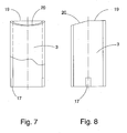
- FIG. 7 shows the rotary sleeve 3 in a sectional view with a first partial ring 19 and a second partial ring 20, which is aligned approximately at an angle of 15 ° to the first partial ring 19. at corresponding rotation of the rotary sleeve prevents the radial surface 19 of the first sub-ring pivoting of the mast tube part by the abutment surface 18 of the flange 5 abuts against the radial surface 19.
- the stop surface 18 of the flange 5 is located opposite the second partial ring 20, so that a pivoting of the upper part of the mast by up to 15 ° is possible until the stop surface 18 abuts against the second partial ring 20.
- Fig. 8 shows the rotary sleeve of Fig. 7 in a rotated position by 90 °.
- both the mast base and the mast top can be made of aluminum tube and also the tilt joint can be made of aluminum.
- the visible outer sides of the flange 5 and the limiting ring 9 can be polished.
- an additional pin fuse is used in which a locking pin is guided radially through corresponding holes of the tilting joint.
- the second foot part which is anchored in the mast lower part, is rotatably held in a series of positions in the mast lower part in order to be able to set different azimuth angles of the tilted screen.
- the backup of the respective positions can z. B. be achieved by a sufficiently strong locking connection or by using locking pins.
Landscapes
- Walking Sticks, Umbrellas, And Fans (AREA)
Priority Applications (2)
| Application Number | Priority Date | Filing Date | Title |
|---|---|---|---|
| EP05005321A EP1700535A1 (fr) | 2005-03-11 | 2005-03-11 | Support pour parapluies ou similaire |
| DE200520014717 DE202005014717U1 (de) | 2005-03-11 | 2005-03-11 | Schirmständer für Sonnenschirme o.dgl. |
Applications Claiming Priority (1)
| Application Number | Priority Date | Filing Date | Title |
|---|---|---|---|
| EP05005321A EP1700535A1 (fr) | 2005-03-11 | 2005-03-11 | Support pour parapluies ou similaire |
Publications (1)
| Publication Number | Publication Date |
|---|---|
| EP1700535A1 true EP1700535A1 (fr) | 2006-09-13 |
Family
ID=34934200
Family Applications (1)
| Application Number | Title | Priority Date | Filing Date |
|---|---|---|---|
| EP05005321A Withdrawn EP1700535A1 (fr) | 2005-03-11 | 2005-03-11 | Support pour parapluies ou similaire |
Country Status (1)
| Country | Link |
|---|---|
| EP (1) | EP1700535A1 (fr) |
Cited By (1)
| Publication number | Priority date | Publication date | Assignee | Title |
|---|---|---|---|---|
| WO2020035841A1 (fr) * | 2018-08-14 | 2020-02-20 | Walberg Urban Electrics Gmbh | Trottinette rabattable à poignées de direction pliables et guidon de ce type |
Citations (6)
| Publication number | Priority date | Publication date | Assignee | Title |
|---|---|---|---|---|
| DE8703822U1 (de) | 1986-06-10 | 1987-10-08 | Babl, Arthur, 8044 Unterschleißheim | Sonnenschutzschirm |
| EP0368539A2 (fr) * | 1988-11-09 | 1990-05-16 | Hoyland Fox Limited | Armature de parapluie |
| EP0623297A2 (fr) * | 1993-04-27 | 1994-11-09 | Sol Camping Industries Ltd. | Parapluie |
| WO2001067914A1 (fr) * | 2000-03-07 | 2001-09-20 | August Albert Ordelman | Ensemble manche pour parasol, parapluie ou analogue |
| US6364562B1 (en) * | 2001-01-11 | 2002-04-02 | Benson Tung | Tiltable sunshade |
| US20030051747A1 (en) * | 2001-09-17 | 2003-03-20 | Jin-Sheng Lai | Automatic bending-angle changing structure for umbrella |
-
2005
- 2005-03-11 EP EP05005321A patent/EP1700535A1/fr not_active Withdrawn
Patent Citations (6)
| Publication number | Priority date | Publication date | Assignee | Title |
|---|---|---|---|---|
| DE8703822U1 (de) | 1986-06-10 | 1987-10-08 | Babl, Arthur, 8044 Unterschleißheim | Sonnenschutzschirm |
| EP0368539A2 (fr) * | 1988-11-09 | 1990-05-16 | Hoyland Fox Limited | Armature de parapluie |
| EP0623297A2 (fr) * | 1993-04-27 | 1994-11-09 | Sol Camping Industries Ltd. | Parapluie |
| WO2001067914A1 (fr) * | 2000-03-07 | 2001-09-20 | August Albert Ordelman | Ensemble manche pour parasol, parapluie ou analogue |
| US6364562B1 (en) * | 2001-01-11 | 2002-04-02 | Benson Tung | Tiltable sunshade |
| US20030051747A1 (en) * | 2001-09-17 | 2003-03-20 | Jin-Sheng Lai | Automatic bending-angle changing structure for umbrella |
Cited By (1)
| Publication number | Priority date | Publication date | Assignee | Title |
|---|---|---|---|---|
| WO2020035841A1 (fr) * | 2018-08-14 | 2020-02-20 | Walberg Urban Electrics Gmbh | Trottinette rabattable à poignées de direction pliables et guidon de ce type |
Similar Documents
| Publication | Publication Date | Title |
|---|---|---|
| DE69925001T2 (de) | Aufrichtbarer unterstand mit zusammenlegbarer zentraldachunterstützung | |
| DE10311665B3 (de) | Zelt | |
| EP1097652B1 (fr) | Parasol à potence | |
| AT408408B (de) | Grossschirm | |
| DE102007021400B4 (de) | Schirm | |
| EP0052258A2 (fr) | Parasol | |
| DE2732654B2 (de) | Gelenkbeschlag für Leiterteile | |
| EP3191771A1 (fr) | Dispositif de maintien pour module solaire placé sur une balustrade de balcon | |
| DE29906116U1 (de) | Standschirm | |
| EP1700535A1 (fr) | Support pour parapluies ou similaire | |
| DE29916824U1 (de) | Einschraubbare Bodenhülse | |
| DE3150765C2 (fr) | ||
| DE202005014717U1 (de) | Schirmständer für Sonnenschirme o.dgl. | |
| DE3142474C2 (fr) | ||
| DE202022103177U1 (de) | Standschirm mit gelenkig angeordneten Dachstreben | |
| DE10125996A1 (de) | Armlehne, insbesondere für einen Bürostuhl | |
| DE1683027C3 (de) | Markise mit Gelenkarmen | |
| DE202007002241U1 (de) | Bespannungsausrichtungsvorrichtung für einen großformatigen Schirm | |
| EP1040771A2 (fr) | Parapluie | |
| DE202017104523U1 (de) | Masthalter | |
| DE102017116844B3 (de) | Stabilisatorstangeneinheit für Sonnenschutz | |
| DE202005005137U1 (de) | Winkelverstellvorrichtung für die Schirmdecke eines Hänge-Schirms | |
| DE10133076B4 (de) | Baustellen-Sicherheitstür | |
| DE2504159A1 (de) | Halterung fuer gelenkarmmarkisen | |
| DE29611165U1 (de) | Standschirm, beispielsweise Sonnenschirm |
Legal Events
| Date | Code | Title | Description |
|---|---|---|---|
| PUAI | Public reference made under article 153(3) epc to a published international application that has entered the european phase |
Free format text: ORIGINAL CODE: 0009012 |
|
| AK | Designated contracting states |
Kind code of ref document: A1 Designated state(s): AT BE BG CH CY CZ DE DK EE ES FI FR GB GR HU IE IS IT LI LT LU MC NL PL PT RO SE SI SK TR |
|
| AX | Request for extension of the european patent |
Extension state: AL BA HR LV MK YU |
|
| AKX | Designation fees paid | ||
| STAA | Information on the status of an ep patent application or granted ep patent |
Free format text: STATUS: THE APPLICATION IS DEEMED TO BE WITHDRAWN |
|
| 18D | Application deemed to be withdrawn |
Effective date: 20070314 |
|
| REG | Reference to a national code |
Ref country code: DE Ref legal event code: 8566 |