EP1700546A2 - Gardinenstange - Google Patents
Gardinenstange Download PDFInfo
- Publication number
- EP1700546A2 EP1700546A2 EP06251312A EP06251312A EP1700546A2 EP 1700546 A2 EP1700546 A2 EP 1700546A2 EP 06251312 A EP06251312 A EP 06251312A EP 06251312 A EP06251312 A EP 06251312A EP 1700546 A2 EP1700546 A2 EP 1700546A2
- Authority
- EP
- European Patent Office
- Prior art keywords
- pole
- supporting
- pieces
- piece
- slanted
- Prior art date
- Legal status (The legal status is an assumption and is not a legal conclusion. Google has not performed a legal analysis and makes no representation as to the accuracy of the status listed.)
- Withdrawn
Links
- 230000015572 biosynthetic process Effects 0.000 claims description 2
- 238000010276 construction Methods 0.000 description 3
- 239000004677 Nylon Substances 0.000 description 1
- 239000000853 adhesive Substances 0.000 description 1
- 230000001070 adhesive effect Effects 0.000 description 1
- XAGFODPZIPBFFR-UHFFFAOYSA-N aluminium Chemical compound [Al] XAGFODPZIPBFFR-UHFFFAOYSA-N 0.000 description 1
- 229910052782 aluminium Inorganic materials 0.000 description 1
- 239000004411 aluminium Substances 0.000 description 1
- 238000005452 bending Methods 0.000 description 1
- 239000000463 material Substances 0.000 description 1
- 229920001778 nylon Polymers 0.000 description 1
- 239000002023 wood Substances 0.000 description 1
Images


Classifications
-
- A—HUMAN NECESSITIES
- A47—FURNITURE; DOMESTIC ARTICLES OR APPLIANCES; COFFEE MILLS; SPICE MILLS; SUCTION CLEANERS IN GENERAL
- A47H—FURNISHINGS FOR WINDOWS OR DOORS
- A47H1/00—Curtain suspension devices
- A47H1/10—Means for mounting curtain rods or rails
- A47H1/12—Adjustable mountings
- A47H1/122—Adjustable mountings for curtain rods
-
- A—HUMAN NECESSITIES
- A47—FURNITURE; DOMESTIC ARTICLES OR APPLIANCES; COFFEE MILLS; SPICE MILLS; SUCTION CLEANERS IN GENERAL
- A47H—FURNISHINGS FOR WINDOWS OR DOORS
- A47H1/00—Curtain suspension devices
- A47H1/02—Curtain rods
-
- A—HUMAN NECESSITIES
- A47—FURNITURE; DOMESTIC ARTICLES OR APPLIANCES; COFFEE MILLS; SPICE MILLS; SUCTION CLEANERS IN GENERAL
- A47H—FURNISHINGS FOR WINDOWS OR DOORS
- A47H1/00—Curtain suspension devices
- A47H1/10—Means for mounting curtain rods or rails
- A47H1/14—Brackets for supporting rods or rails
- A47H1/142—Brackets for supporting rods or rails for supporting rods
-
- A—HUMAN NECESSITIES
- A47—FURNITURE; DOMESTIC ARTICLES OR APPLIANCES; COFFEE MILLS; SPICE MILLS; SUCTION CLEANERS IN GENERAL
- A47H—FURNISHINGS FOR WINDOWS OR DOORS
- A47H1/00—Curtain suspension devices
- A47H1/02—Curtain rods
- A47H2001/0205—Curtain rods being curved
Definitions
- the present invention relates to curtain poles.
- Curtain poles are used extensively for hanging curtains.
- the usual form of such devices comprises an elongate pole, generally but not always made of wood, which carries rings, slidable along the pole, from which the curtains are suspended.
- the pole itself is supported adjacent to it's ends, and at it's midpoint when the pole is intended for use with a pair of curtains.
- the present invention seeks to provide a pole construction which enables curtain poles to follow a bend without significantly detracting from the appearance of the pole.
- the applicant's earlier patent no. GB234834 relates to a pole corner arrangement to allow curtain poles to be used in locations where a bend is required.
- the product has proven reasonably successful, the applicant has found a number of disadvantages with the construction. In particular, it has proven to be extremely difficult accurately to cut the wooden corner pieces to the desired angles and planes to allow accurate abutment of the corner pieces.
- movement between the corner pieces of the pole causes a force to be exerted at the areas in which the pole is supported to the wall, resulting in movement of the pole at these points when the curtains are opened or drawn.
- the present invention seeks to provide an improved pole construction to overcome or at least alleviate the aforementioned disadvantages.
- a supporting pole for connection to wall surface, the pole having a circular or substantially circular cross-section with at least one flattened side.
- a curtain pole having a circular or substantially circular cross section with at least one flattened side, the pole comprising a plurality of the pole pieces each cut transversely from a unitary pole and having at one or each end an inclined face, and means for connecting the pole pieces together to produce a unitary pole having a centre line which diverges from the centre line of the original uncut pole.
- pole pieces and adjacent pole parts are formed with recesses for connection together via dovetail joints.
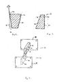
- Figure 1 shows a corner arrangement 2 for a curtain pole 4.
- the corner arrangement comprises five intermediate pole pieces 6 and two end pole pieces 8. Each end pole piece 8 is connected to adjacent pole parts 10.
- Figures 2 to 4 show, in perspective and cross-section, an intermediate pole piece 6.
- the pole piece 6 is of short length and has a circular cross section with one flattened side 12.
- the ends 14, 16 of the pole piece 6 are transversely slanted at an angle to the diametral plane, indicated at 18. Both ends are slanted in opposite directions by the same angle so as to form an isosceles wedge like formation in plan view.
- the angle may, for example, be 15 ° but other angles may be used.
- Figure 6 shows an end pole piece 8.
- the only difference between the intermediate pole piece 6 and the end pole piece 8 is that the end pole piece 8 has only one slanted end surface 20, the other end surface 22 lies in the diametral plane at right angles to the axis of the pole piece 8.
- the intermediate and end pole pieces 6, 8 have a recess 24 formed in both end walls 14, 16, 20, 22. As can be seen in Figure 1, the pole pieces 6, 8, 10 are all connected together via dovetail-shaped wedges 26 received within the recesses 24 formed in the end walls of each pole piece 6, 8, 10.
- Adhesive may be additionally used to retain the pole pieces 6, 8, 10 firmly against one another without the need for a tensioning element.
- the pole pieces 6, 8, 10 are attached together in such a way that the resultant pole formed has a flattened side extending along the entire length of the pole 4.
- pole pieces 6, 8, 10 have a flattened sides allows the end surfaces 14, 16 to be accurately cut to the desired angle .
- a strip of nylon, or similar material is located on the top surface of the pole pieces and parts 6, 8, 10 and extends along the length of the entire pole 4 to allow curtain rings placed around the pole 4 to slide back and forth along the pole without being subjected to frictional forces.
- the bottom surface of the pole pieces and parts 6, 8, 10 includes a recess for receiving a track, made for example of aluminium, which extends along the entire length of the pole 4.
- the track includes attachment members slidable back and forth along the track to which curtains can be attached.
- FIG. 6 illustrates a wall clamp 30 suitable for attaching the curtain pole 4 to a wall.
- the wall clamp 30 comprises a back plate 32 for attachment to a walled surface.
- the plate 32 has apertures formed therethrough to allow the plate 32 be attached to the wall using conventional means.
- a U-shaped connecting plate 34 extends perpendicularly from the back plate 32.
- the connecting plate 34 has elongate apertures 36 formed in each side wall.
- the wall clamp 30 is connected to a curtain pole clamp 36.
- the pole clamp 36 comprises a back plate 38 which, in use, is attached to the flattened side surface 12 of the pole 4.
- a connecting plate 40 extends perpendicularly from the back plate 38.
- the connecting plate 40 has an aperture 42 extending therethrough.
- the connecting plate 40 of the pole clamp 36 in use, is placed within the side walls of the U-shaped connecting plate 34 and the two plates 34, 40 are connected together via the conventional nut and bolt arrangement through the apertures 36, 42.
- the elongate apertures 36 of the connecting plate 34 allows for adjustment of the connection between the clamps 30, 36.
- Figure 7 illustrates a further wall clamp 44 suitable for attaching the curtain pole 4 to a wall.
- the wall clamp 44 comprises a back plate 46 for attachment to a walled surface.
- the plate 46 has apertures formed therethrough to allow the plate 46 to be attached to the wall using conventional means.
- a connecting plate 48 extends perpendicularly from the top edge of back plate.
- An elongate aperture 50 is formed through a central area of the top plate.
- An identically shaped curtain clamp 52 has a connecting plate 54 for attachment to the flattened side surfaces 12 of the pole.
- the two clamps 44, 52 are connected together via a conventional nut and bolt arrangement through the elongate apertures 50, 56.
- the elongate apertures 50, 56 of the connecting plates 48, 54 allows for adjustment of the connection between the clamps 44, 52.
- pole and clamp embodiments described above may be modified without departing from the scope of the invention.
- the arrangement of the invention can provide any suitable type of bend which can be achieved by selection of the right number of intermediate pieces 6.
- shallow curves and steep curves be allowed for as well as more sophisticated shapes such as "S" bends.
Landscapes
- Curtains And Furnishings For Windows Or Doors (AREA)
Applications Claiming Priority (1)
| Application Number | Priority Date | Filing Date | Title |
|---|---|---|---|
| GB0505032A GB2423918B (en) | 2005-03-11 | 2005-03-11 | Curtain pole |
Publications (2)
| Publication Number | Publication Date |
|---|---|
| EP1700546A2 true EP1700546A2 (de) | 2006-09-13 |
| EP1700546A3 EP1700546A3 (de) | 2008-05-21 |
Family
ID=34508903
Family Applications (1)
| Application Number | Title | Priority Date | Filing Date |
|---|---|---|---|
| EP06251312A Withdrawn EP1700546A3 (de) | 2005-03-11 | 2006-03-13 | Gardinenstange |
Country Status (3)
| Country | Link |
|---|---|
| US (1) | US20060219855A1 (de) |
| EP (1) | EP1700546A3 (de) |
| GB (1) | GB2423918B (de) |
Families Citing this family (2)
| Publication number | Priority date | Publication date | Assignee | Title |
|---|---|---|---|---|
| US20120223039A1 (en) * | 2011-03-02 | 2012-09-06 | Keith Malmstadt | Curtain Rod Assembly |
| WO2021186526A1 (ja) * | 2020-03-17 | 2021-09-23 | 三菱電機株式会社 | 回転電機 |
Citations (1)
| Publication number | Priority date | Publication date | Assignee | Title |
|---|---|---|---|---|
| GB234834A (en) | 1924-05-30 | 1926-03-18 | Henri George | Process and apparatus for increasing the ultra-violet radiation from mercury vapour lamps made of quartz |
Family Cites Families (8)
| Publication number | Priority date | Publication date | Assignee | Title |
|---|---|---|---|---|
| US2705566A (en) * | 1951-10-23 | 1955-04-05 | Kirsh Company | Curtain rod and support therefor |
| GB855130A (en) * | 1956-05-11 | 1960-11-30 | Andrew George Heron | Improvements in or relating to extruded plastic strippings |
| DE2700838A1 (de) * | 1977-01-11 | 1978-07-13 | Erwin Hepperle | Vorhangschienengarnitur |
| US4999874A (en) * | 1990-02-21 | 1991-03-19 | White Gerald N | Drapery rod assembly and cover |
| US5535897A (en) * | 1993-03-19 | 1996-07-16 | Gobidas; Raphael A. | Drapery rod with wood veneer and method of making same |
| DE19648404C2 (de) * | 1996-11-22 | 1999-05-20 | Udo Heider | Vorhangstange |
| US6391414B1 (en) * | 1997-03-07 | 2002-05-21 | Pharmacia Ab | Structure and method for joining parts |
| GB2343834B (en) * | 1998-10-19 | 2002-07-31 | Orazio Gualtieri | Curtain pole |
-
2005
- 2005-03-11 GB GB0505032A patent/GB2423918B/en not_active Expired - Fee Related
-
2006
- 2006-03-13 US US11/373,165 patent/US20060219855A1/en not_active Abandoned
- 2006-03-13 EP EP06251312A patent/EP1700546A3/de not_active Withdrawn
Patent Citations (1)
| Publication number | Priority date | Publication date | Assignee | Title |
|---|---|---|---|---|
| GB234834A (en) | 1924-05-30 | 1926-03-18 | Henri George | Process and apparatus for increasing the ultra-violet radiation from mercury vapour lamps made of quartz |
Also Published As
| Publication number | Publication date |
|---|---|
| GB2423918B (en) | 2008-05-21 |
| GB0505032D0 (en) | 2005-04-20 |
| GB2423918A (en) | 2006-09-13 |
| US20060219855A1 (en) | 2006-10-05 |
| EP1700546A3 (de) | 2008-05-21 |
Similar Documents
| Publication | Publication Date | Title |
|---|---|---|
| US4648231A (en) | Structural joint element for panels | |
| US6164028A (en) | Reinforced steel stud structure | |
| US5904023A (en) | Steel stud stabilizing clip | |
| US9115506B2 (en) | Wood to pipe bracket and a connection utilizing such a bracket | |
| US7104024B1 (en) | Connector for connecting two building members together that permits relative movement between the building members | |
| US4188019A (en) | Fencing construction | |
| US5111632A (en) | Expandable joist hanger | |
| US7152849B2 (en) | Fastener | |
| US8910452B2 (en) | Hurricane tie fastener and method of use | |
| FI100120B (fi) | Kalteva katto, joka on katettu kattotiilillä ja tämän tyyppisessä kato ssa käytettävä tiilikoukku | |
| CA2645824C (en) | Improved connections for suspended ceiling system | |
| US20220154464A1 (en) | Ceiling system | |
| KR910015760A (ko) | 콘크리트 완성품을 위한 강철편 콘크리트 앵커(anchor) | |
| US5839233A (en) | Louvre type roof structures | |
| EP1700546A2 (de) | Gardinenstange | |
| EP2924186A1 (de) | Nagelplattenhängevorrichtung mit biegbarer lasche | |
| US5695166A (en) | Post support | |
| SE435541B (sv) | Festelement | |
| CA2171140A1 (en) | Connector | |
| AU2004200395B2 (en) | Building Frame Member | |
| US11634926B2 (en) | Fence bracket | |
| NZ545164A (en) | Sheet metal bracket stock with diamond or square shaped apertures | |
| JP6778090B2 (ja) | ハンガーと該ハンガーを用いたシステム天井構造 | |
| US20040139672A1 (en) | System for making walls | |
| EP0004196B1 (de) | Tragarm für Regal |
Legal Events
| Date | Code | Title | Description |
|---|---|---|---|
| PUAI | Public reference made under article 153(3) epc to a published international application that has entered the european phase |
Free format text: ORIGINAL CODE: 0009012 |
|
| AK | Designated contracting states |
Kind code of ref document: A2 Designated state(s): AT BE BG CH CY CZ DE DK EE ES FI FR GB GR HU IE IS IT LI LT LU LV MC NL PL PT RO SE SI SK TR |
|
| AX | Request for extension of the european patent |
Extension state: AL BA HR MK YU |
|
| PUAL | Search report despatched |
Free format text: ORIGINAL CODE: 0009013 |
|
| AK | Designated contracting states |
Kind code of ref document: A3 Designated state(s): AT BE BG CH CY CZ DE DK EE ES FI FR GB GR HU IE IS IT LI LT LU LV MC NL PL PT RO SE SI SK TR |
|
| AX | Request for extension of the european patent |
Extension state: AL BA HR MK YU |
|
| AKX | Designation fees paid | ||
| REG | Reference to a national code |
Ref country code: DE Ref legal event code: 8566 |
|
| STAA | Information on the status of an ep patent application or granted ep patent |
Free format text: STATUS: THE APPLICATION IS DEEMED TO BE WITHDRAWN |
|
| 18D | Application deemed to be withdrawn |
Effective date: 20081122 |