EP1700664A1 - Méthode et appareil pour contrôler le pointage d'un fil de soudage - Google Patents
Méthode et appareil pour contrôler le pointage d'un fil de soudage Download PDFInfo
- Publication number
- EP1700664A1 EP1700664A1 EP06251291A EP06251291A EP1700664A1 EP 1700664 A1 EP1700664 A1 EP 1700664A1 EP 06251291 A EP06251291 A EP 06251291A EP 06251291 A EP06251291 A EP 06251291A EP 1700664 A1 EP1700664 A1 EP 1700664A1
- Authority
- EP
- European Patent Office
- Prior art keywords
- wire
- torch
- aiming
- displacement
- welding
- Prior art date
- Legal status (The legal status is an assumption and is not a legal conclusion. Google has not performed a legal analysis and makes no representation as to the accuracy of the status listed.)
- Granted
Links
Images



Classifications
-
- B—PERFORMING OPERATIONS; TRANSPORTING
- B23—MACHINE TOOLS; METAL-WORKING NOT OTHERWISE PROVIDED FOR
- B23K—SOLDERING OR UNSOLDERING; WELDING; CLADDING OR PLATING BY SOLDERING OR WELDING; CUTTING BY APPLYING HEAT LOCALLY, e.g. FLAME CUTTING; WORKING BY LASER BEAM
- B23K9/00—Arc welding or cutting
- B23K9/12—Automatic feeding or moving of electrodes or work for spot or seam welding or cutting
- B23K9/127—Means for tracking lines during arc welding or cutting
- B23K9/1272—Geometry oriented, e.g. beam optical trading
- B23K9/1274—Using non-contact, optical means, e.g. laser means
-
- B—PERFORMING OPERATIONS; TRANSPORTING
- B23—MACHINE TOOLS; METAL-WORKING NOT OTHERWISE PROVIDED FOR
- B23K—SOLDERING OR UNSOLDERING; WELDING; CLADDING OR PLATING BY SOLDERING OR WELDING; CUTTING BY APPLYING HEAT LOCALLY, e.g. FLAME CUTTING; WORKING BY LASER BEAM
- B23K9/00—Arc welding or cutting
- B23K9/12—Automatic feeding or moving of electrodes or work for spot or seam welding or cutting
- B23K9/126—Controlling the spatial relationship between the work and the gas torch
Definitions
- the present invention relates to a wire aiming position control method and position control apparatus in a consumable electrode type arc welding method.
- a welding wire is packed or passed through a wire guide conduit. Therefore, by passing a pack or a wire guide conduit, a wire has a twist and is fed from a tip. That is, a welding wire coming out from a tip is twisted and fed while being rotated owing to a clearance between an inner diameter of the tip and an outer diameter of the welding wire and the twist of the welding wire. Therefore, there poses a problem that arc is not generated at a predetermined aiming position of a welded member and stable arc start and uniform bead shape are not constituted.
- a welding wire taken out from a wire pack or a reel has a twist, and still further twist of the wire is changed by a wire path from the pack to a torch, a wire front end portion is changed when fed from a tip front end and therefore, it is very difficult to feed the front end position of the welding wire accurately to the aiming position.
- an arc welding torch capable of generating arc at a predetermined aiming position (refer to, for example, Patent Reference 1) .
- a torch described in Patent Reference 1 is provided with a plurality of pieces of curves as a wire guide path, and a rotation hampering torque is set to be larger than a torsional yield torque of a welding wire by a friction force by radii of curvature and circular arc angles of the respective curves and an elastic force of the welding wire brought into contact therewith. Therefore, when a rotational torque is operated to the welding wire, the welding wire itself is twisted to absorb a rotational displacement to prevent the welding wire from being rotated at inside of the wire guide path of the torch. Thereby, a front end of the welding wire is made to be disposed always at the same position relative to a power feeding tip and arc is generated at a predetermined aiming position.
- Patent Reference 2 JP-A-9-29441
- Patent reference 2 JP-A-11-216565
- the invention has been carried out in order to resolve the drawback of the related art and it is an object thereof to provide wire aiming position control method and position control apparatus capable of accurately feeding a welding wire to an aiming position of a welded member regardless of a change in an amount of twisting the wire and a change in an amount of wearing a tip. Further, it is an object of the invention to provide the aiming position control method and position control apparatus capable of accurately ensuring an aiming position of a torch and capable of ensuring stable welding quality even in thin plate welding by enabling accurate reproduction of a welding condition including a torch angle.
- a wire aiming position control method comprising the steps of calculating an intersection K1 of a linear line L1 connecting a front end center of a tip 10 and a wire front end and an extension plane L2 including an imaginary aiming position K, calculating a wire displacement C constituting a distance between the intersection K1 and the imaginary aiming position K, and correcting at least either one of the welding wire W and a welded member 14 by an amount of the wire displacement C along the extension plane L2.
- the wire displacement constituting the distance between the intersection and the imaginary aiming position can be calculated by calculating the intersection of the linear line connecting the front end center of the tip and the wire front end and the extension plane including the imaginary aiming position.
- the wire displacement is an accurate displacement of a front end position of the welding wire and by correcting by the amount of the displacement, the welding wire can accurately be fed to the aiming position (welding position) of the welded member. That is, even when an amount of twisting the welding wire is changed for packing or in passing a guide conduit, the twisted amount can be predicted and the wire displacement can accurately be operated. Therefore, the welding wire can accurately be fed to the aiming position of the welded member regardless of a change in the wire twisting amount.
- the welding wire can accurately be fed to the aiming position of the welded member and the welded portion can be maintained constant even in thin plate welding or the like.
- a stable bonding strength can be ensured and quality of the welded portion can be stabilized.
- the detection and calculation of the displacement can be carried out in a short period of time and a time period of welding operation can be shortened.
- a wire aiming position control apparatus comprising:
- the wire aiming position control apparatus of the invention by the first operating means, the imaginary aiming position of the predetermined position can be operated, further, by the second operating means, the wire displacement constituting the distance between the intersection (the intersection of the linear line connecting the front end center of the tip and the wire front end and the extension plane) and the imaginary aiming position can be calculated, further, by the correcting means, the position of feeding the welding wire can be corrected by the calculated amount of the wire displacement. That is, the wire displacement is an accurate displacement of the front end position of the welding wire and by correcting by the amount of the wire displacement, the welding wire can accurately be fed to the aiming position of the welded member.
- the wire aiming position control apparatus when used, even when the amount of twisting the welding wire is changed for packing or in passing a guide conduit, the twisting amount can be measured and the wire displacement can accurately be operated. Therefore, the welding wire can accurately be fed to the aiming position of the welded member and a depth of melting the welded portion can be maintained constant even in thin plate welding or the like. As a result, the stable bonding strength can be ensured and the quality of the welded portion can be stabilized. Further, since two points of the front end center of the tip and the wire front end are detected, detection and calculation of the displacement can be carried out in a short period of time and a time period of the welding operation can shortened.
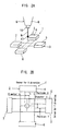
- FIGS. 2A and 2B are schematic views of a wire aiming position measuring apparatus.
- the wire aiming position measuring apparatus is provided with wire front end position measuring means 1, a wire front end position measured by the wire front end position measuring means 1 is operated by comparing data measured by a laser sensor and Z direction displacement data of a welding robot 16 (refer to FIG. 3) with master data, and deviation amount (displacement difference) data is transmitted to a robot controller to correct to a set imaginary aiming position, K (refer to FIG. 1).
- the wire front end position measuring means 1 comprises a pair of laser sensors 2, 3 and the respective laser sensors 2, 3 include laser projectors 4, 5 and laser receivers 6, 7. Further, a data operation apparatus and the robot controller are not illustrated.
- the wire aiming position control apparatus is provided with first operating means 11 (refer to FIG. 3) for operating a reference value (master data) of the imaginary aiming position K, second operating means (displacement operating means) 12 for calculating a wire displacement C relative to the imaginary aiming position K and correcting means 15 for correcting a position of feeding a welding wire w by an amount of the wire displacement C. That is, a front end (tip) of an arm of the welding robot 16 is attached with a torch 9, welding is carried out while moving the torch 9 as instructed by operating the arm by robot control means, when the position of feeding the welding wire W is shifted from the imaginary aiming position K, the shift is corrected.
- the imaginary aiming position K is a point disposed at a predetermined position and a plane including the imaginary aiming position K is referred to as an extension plane L2.
- the extension plane L2 is orthogonal to a center line L of a tip 10.
- the second operating means 12 calculates the wire displacement C which is a distance between an intersection K1 (an intersection of a linear line L1 connecting a center of a front end of the tip 10 and a front end of the wire and the extension plane L2) and the imaginary aiming position K.
- the torch 9 comprises a nozzle 8 and the tip 10 arranged at a front end of the nozzle 8.
- the welding wire W is supplied to the torch 9 by way of a wire control apparatus 30.
- numeral 31 designates a feeding motor and numeral 32 designates a feeding roll.
- a melted oxidized ball 17 is formed at a front end of the welding wire W.
- the imaginary aiming position K is measured by using a calibrating needle and the imaginary aiming position K is made to constitute wire front end position master data (step S1).
- the imaginary aiming position K becomes a tool registration value in the master data. That is, according to the step, measurement is carried out before starting the operation or in daily check and the imaginary aiming position K is preserved as master data.
- a position and a diameter (outer diameter) dimension of the melted oxidized ball 17 as well as a position and a diameter (outer diameter) dimension of the wire at a lower end position 19 of the tip 10 are measured by a Z direction coordinate value in inserting the robot and an outer shape of the wire as a shadow thereof and a position to the shadow by moving down the robot 16 at constant speed within a measuring range of a pair of the laser sensors in X and Y directions (step S2).
- the operation proceeds to step S3 and calculates an upper end position of the melted oxidized ball 17 from a position at which the outer diameter of the welding wire W is changed.
- step S4 calculates a wire center position 18 at a position of an upper end of the melted oxidized ball 17. That is, the position of the upper end of the melted oxidized ball 17 is calculated as a position at which the diameter of the oxidized ball is changed to the wire diameter.
- step S5 a wire center position 20 at the lower end position 19 of the tip 10 is calculated.
- step S6 the operation proceeds to step S6.
- the operation proceeds to step S7 and calculates a displacement position K1 of the wire front end at the extension plane (Ex plane) L2.
- the displacement position K1 constituting an intersection of the linear line L1 connecting the front end center of the tip 10 and the wire front end (specifically, the linear line L1 three-dimensionally connecting the wire center position 20 at the lower end position 19 of the tip 10 and the wire center position 18 at the upper end position of the melted oxidized ball 17) and the extension plane L2 is calculated as X, Y, Z coordinate values. Further, the operation proceeds to step S8 and calculates a dimension (distance) between the imaginary aiming position K and the displacement position K1 as a wire displacement (deviation amount) C.
- the operation proceeds to step S9 and transmits (registers) the wire displacement C to the correcting means 15 (means included in the robot control means) as a corrected amount of the tool registration value.
- the wire displacement C is a displacement relative to the reference value (tool registration value) of the imaginary aiming position K.
- the reference value of the imaginary aiming position K can be calculated by using a needle for calibrating the torch position.
- the torch position calibrating needle is a needle simulating the position of the front end of the wire extended straight from the tip front end and the front end of the needle constitutes the imaginary aiming position K. Further, the needle is projected from the tip front end by a predetermined amount (extension amount B).
- the tool registration value is calculated in real time after measuring the wire front end position, the wire displacement C is inputted to the welding robot 16 (robot control means), the arm of the robot 16 is corrected along the extension plane L2 by the displacement, and the welding wire W can accurately be fed to an aiming position (welding position) of the welded member 14. Further, the imaginary aiming position K can be calculated by using a new wire or the like by updating the tip 10.
- the imaginary aiming position K can be calculated by the first operating means 11 (in this case, calculated by using the calibrating needle), by the second operating means 12, the intersection K1 (the intersection of the linear line L1 connecting the front end center of the tip 10 and the wire front end and the extension plane L2) and the wire displacement C constituting the distance to the imaginary aiming position K can be calculated, further, by the correcting means 15, the position of feeding the welding wire W can be corrected by the calculated amount of the wire displacement C.
- the wire displacement C is an accurate displacement of the front end position of the welding wire W and by correcting the position of feeding the welding wire W by the amount of the wire displacement C, the welding wire W can accurately be fed to the aiming position (welding position) of the welded member 14.
- the twisted amount of the welding wire w can be measured even when the twisted amount is changed for packing or in passing a guide conduit, and a deformation amount at the wire front end position can accurately be calculated. Therefore, the welding wire W can accurately be fed to the aiming position of the welded member 14 regardless of a change in the twisted amount of the wire. In this way, according to the wire aiming position control method using the wire aiming position control apparatus, the welding wire W can accurately be fed to the aiming position of the welded member 14, and a welded portion can be maintained constant even in thin plate welding or the like. As a result, a stable bonding strength can be ensured and quality of the welded portion can be stabilized.
- the wire displacement can simply and highly accurately be calculated and a stable and highly accurate welded portion can be formed.
- the wire front end is made to constitute the wire center position 18 at the upper end position of the melted oxidized ball 17, the wire displacement can accurately be calculated, and the welding wire W can further accurately be fed to the aiming position. That is, the melted oxidized ball 17 welded at the wire front end is not necessarily melted to attach to the wire center and therefore, when the melted oxidized ball 17 is taken into consideration, there is a possibility that the melted oxidized ball 17 is deviated from the aiming position and therefore, the wire displacement C is calculated by using the wire center position 18 at the upper end position of the melted oxidized ball 17. Therefore, even when the melted oxidized ball 17 is present, the welding wire W can accurately be fed to the aiming position of the welded member 14.
- the displacement C at the front end position of the welding wire W is calculated (operated) from the wire center position at the tip front end position and therefore, even when a diameter of a front end hole of the tip 10 is worn, accurate correction can be carried out.
- the front end center of the tip 10 is made to constitute the wire center position at the lower end position 19 of the tip 10 and therefore, the front end center of the tip 10 can accurately be determined, the wire displacement C can accurately be calculated, and the welding wire w can further accurately be fed to the aiming position.
- extension plane L2 is orthogonal to the center line L of the tip 10 and therefore, even when the displacement is corrected, an extension amount of the welding wire W projected from the tip 10 can be made to be substantially constant to achieve an advantage of capable of efficiently carrying out stable welding operation.
- a reference position of the nozzle 8 when the nozzle 8 is instructed to be disposed at a specific position under a state in which the torch 9 is accurately attached to a predetermined position of the arm of the welding robot 16 and a current position of the nozzle 8 which is instructed to be disposed at a position similarly are shifted from each other.
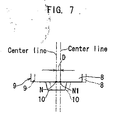
- the nozzle 8 is not present at an instructed position and therefore, the welding position is shifted from the imaginary aiming position K. Therefore, by calculating a torch position displacement D (refer to FIG. 7), even when the torch 9 is deformed, the aiming position of the torch 9 can accurately be ensured.
- a wire aiming position control apparatus in this case is provided with storing means 25 for storing the reference position of the nozzle 8 when the nozzle 8 is instructed to be disposed at the specific position under the state in which the torch 9 is accurately attached to the predetermined position of the arm of the welding robot 16, and measuring means 26 for measuring the current position of the nozzle 8 which is instructed to be disposed at the position similarly, and by operating means 27, the torch position displacement D is calculated based on the reference position stored to the storing means 25 and the measured position measured by the measuring means 26. Further, the respective positions are determined as positions on the torch center line at the lower end position of the nozzle 8.
- Step S11 the reference position of the nozzle 8 is stored. Specifically, the lower end position of the nozzle 8 on the torch center line is stored when specific position instruction is outputted from control means (not illustrated) (as mentioned later, when instruction constituting a position at which the position of the torch 9 can be measured by the measuring means 26 is outputted) under a state in which the torch 9 is accurately attached to the predetermined position of the arm of the welding robot 16.
- Reference position master data is constituted by constituting the lower end position as the reference position. According to the step, measurement is carried out before starting the operation or in daily check to preserve (store) the lower end position as the master data.
- step S12 the position of the nozzle 8 is measured as shown by FIG. 7.
- the lower end position of the nozzle 8 on the torch center line is measured by the measuring means 26 (means constituted by the wire front end position measuring means 1).
- the operation proceeds to step S13 and compares the reference position master data (the reference position stored by the storing means 25) and the measured position measured by the measuring means 26 and calculates the torch position displacement D (refer to FIG. 7) which is a deviation of N1 constituting a measured position from N constituting the reference position in three axes (X, Y, Z axes orthogonal to each other) directions.
- the reference position master data the reference position stored by the storing means 25
- the measured position measured by the measuring means 26 calculates the torch position displacement D (refer to FIG. 7) which is a deviation of N1 constituting a measured position from N constituting the reference position in three axes (X, Y, Z axes orthogonal to each other) directions.
- the torch position displacement D is illustrated as a two-dimensional deviation amount, actually, as described above, a three-dimensional deviation amount can be calculated. Further, a threshold (a threshold of the torch position displacement D) within a range of capable of ensuring the aiming position of the torch 9 can be set.
- the invention is not limited to the embodiments but can be embodied by being variously modified within the range of the invention.
- the pair of laser sensors 2, 3 are used as the wire front end position measuring means 1
- the wire front end position measuring means 1 is not limited to the pair of sensors but may be constituted by a single sensor or a pair or more of sensors. When the sensors are increased, accuracy of measuring the position can be promoted. Further, another position detecting sensor may be used as the wire front end position measuring means 1.
- the wire displacement C on the extension plane L2 can be calculated. That is, even when the melted oxidized ball 17 is not present, the welding wire W can accurately be fed to the aiming position of the welded member 14.
- the wire front end for determining the linear line L1 is the wire center position 18 at the upper end position of the melted oxidized ball 17 according to the embodiment, the invention is not limited thereto but the wire front end may be constituted by a specified portion of the melted oxidized ball 17.
- the extension plane L2 is orthogonal to the center line L of the tip 10, the extension plane L2 may not naturally be orthogonal thereto and can arbitrarily be set.
- the imaginary aiming position K is constituted by the front end position of the calibrating needle mounted to the torch 9, the imaginary aiming position K may be constituted by a calculated position calculated by calculating a point disposed on the center line L of the tip 10 at a predetermined position from the tip 10 without using the calibrating needle.
- the arm of the welding robot 16, that is, the welding wire W is connected in correcting the welded member 14 may be corrected, or the welding wire and the welded member 14 may be corrected.
- the wire displacement C and the torch position displacement D may be absorbed.
- moving along the extension plane L2 includes not only a case of moving in parallel with the extension plane L2 but also a case of moving successively along X axis, Y axis, Z axis orthogonal to each other. That is, in the case of correcting, the welding wire W or the welded member 14 may be moved in steps.
- the reference position of the nozzle 8 and the current position of the nozzle 8 are compared, not only the nozzle 8 but also the tip 10 may be used therefor.
- the wire aiming position control method of the invention comprises the steps of calculating the intersection K1 of the linear line L1 connecting the front end center of the tip 10 and the wire front end and the extension plane L2 including the imaginary aiming position K, calculating the wire displacement C constituting the distance between the intersection K1 and the imaginary aiming position K, and feeding the welding wire W to the imaginary aiming position K by correcting at least one of the welding wire W and the welded member 14 by the amount of the wire displacement C along the extension plane L2.
- the wire displacement constituting the distance between the intersection and the imaginary aiming position can be calculated by calculating the intersection of the linear line connecting the front end center of the tip and the wire front end and the extension plane including the imaginary aiming position.
- the wire displacement is the accurate displacement of the front end position of the welding wire and by correcting by the amount of the displacement, the welding wire can accurately be fed to the aiming position (welding position) of the welded member. That is, even when the twisted amount of the welding wire is changed for packing or in passing a guided conduit, the twisted amount can be predicted and the wire displacement can accurately be calculated. Therefore, the welding wire can accurately be fed to the aiming position of the welded member regardless of the change in the wire twisting amount.
- the welding wire can accurately be fed to the aiming position of the welded member and the welded portion _ can be maintained constant even in thin plate welding or the like.
- the stable bonding strength can be ensured and the quality of the welded portion can be stabilized.
- the detection and the calculation of the displacement can be carried out in the short period of time and the time period of the welding operation can be shortened.
- the extension plane L2 when the extension plane L2 is orthogonal to the center line L of the tip 10, the extension plane is orthogonal to the center line of the tip and therefore, even when the displacement is corrected, the extension amount of the welding wire projected from the tip can substantially be made to be constant and the stable welding operation can efficiently be carried out.
- the wire aiming position control method when the imaginary aiming position is determined as the front end portion of the calibrating needle mounted to the torch 9, the imaginary aiming position is determined as the front end position of the calibrating needle mounted to the torch 9 and therefore, the wire displacement can simply and highly accurately be calculated and the stable highly accurate welded portion can be formed.
- the wire front end when the wire front end is made to be disposed at the wire center position 18 at the upper end position of the melted oxidized ball 17, the wire front end is made to be disposed at the wire center position at the upper end position of the melted oxidized ball and therefore, the wire displacement can accurately be calculated and the welding wire can further accurately be fed to the aiming position. That is, the melted oxidized ball welded at the wire front end is not necessarily be melted to be attached to the wire center and therefore, when the melted oxidized ball is taken into consideration, there is a possibility of deviating the melted oxidized ball from the aiming position and therefore, the wire displacement is calculated by using the upper end position of the melted oxidized ball. Therefore, even when the melted oxidized ball is present, the welding wire can accurately be fed to the aiming position of the melted member.
- the wire aiming position control method when the front end center of the tip 10 is disposed at the wire center position 20 at the lower end position 19 of the tip 10, the front end center of the tip is disposed at the wire center position at the lower end position of the tip and therefore, the front end center of the tip can accurately be determined, the wire displacement can accurately be calculated, and the welding wire can further accurately be fed to the aiming position.
- the wire displacement C is calculated after correcting the torch position by the amount of the torch position displacement D by calculating the torch position displacement D by storing the reference position of the torch 9 when the torch 9 is instructed to be disposed at the specific position under the state in which the torch 9 is accurately attached to the predetermined position of the arm of the welding robot 16, measuring the current position of the torch 9 when instructed to be disposed at the position similarly, and calculating the torch position displacement D based on the reference position and the measured position.
- the torch position displacement constituting the current positional shift of the torch relative to the reference position of the torch can be calculated when the torch 9 is instructed to be disposed at the specific position under the state in which the torch is accurately attached to the predetermined position of the arm of the welding robot. That is, in the case in which the positional shift of the torch is produced, when the wire displacement is calculated while the displacement of the torch position is not corrected, the wire displacement becomes the inaccurate displacement relative to the imaginary aiming position.
- the wire displacement is calculated after correcting the displacement of the torch position, even when the tip or the like is deformed by being interfered with a welded member, a fixed jig or the like, the welding condition including the torch angle can accurately be reproduced, the aiming position of the torch can accurately be ensured even in thin plate welding and the stable welding quality can be ensured.
- the reference position and the measured position of the torch 9 are determined as positions on the torch center line at the lower end position of the nozzle 8
- the reference position and the measured position of the torch can be determined as the positions on the torch center line at the lower position of the nozzle and therefore, the displacement of the torch position can simply be calculated and reliability of calculating the displacement of the torch position is promoted.
- the wire aiming position control apparatus of the invention comprises the first operating means 11 for operating the imaginary aiming position K constituting a predetermined position; the second operating means 12 for calculating the intersection K1 of the linear line L1 connecting the front end center of the tip 10 and the wire front end and the extension plane L2 including the imaginary aiming position K and calculating the wire displacement C constituting the distance between the intersection K1 and the imaginary aiming position K; and the correcting means 15 for correcting the position of feeding the welding wire W by moving at least one of the welding wire W and the welded member 14 along the extension plane L2 by the calculated amount of the wire displacement C.
- the imaginary aiming position of the predetermined position can be operated by the first operating means, further, by the second operating means, the wire displacement constituting the distance between the intersection (the intersection of the linear line connecting the front end center of the tip and the wire front end and the extension plane) and the imaginary aiming position, further, by the correcting means, the position of feeding the welding wire can be corrected by the calculated amount of the wire displacement. That is, the wire displacement is the accurate displacement of the front end position of the welding wire and by correcting the position by the amount of the wire displacement, the welding wire can accurately be fed to the aiming position of the welded member.
- the wire aiming position control apparatus when used, even when the twisted amount of the welding wire is changed for packing or in passing a guide conduit, the twisted amount can be measured, and the wire displacement can accurately be operated. Further, the welding wire can accurately be fed to the aiming position of the welded member and a melted depth of the welded portion can be maintained constant even in thin plate welding or the like. As a result, the stable bonding strength can be ensured, and the quality of the welded portion can be stabilized. Further, since two points of the front end center of the tip and the wire front end are detected, the detection and calculation of the displacement can be carried out in a short period of time and the time period of the welding operation can be shortened.
- the extension plane L2 when the extension plane L2 is orthogonal to the center line L of the tip 10, the extension plane is orthogonal to the center line of the tip and therefore, even when the displacement is corrected, the extension amount of the welding wire projected from the tip can be made to be substantially constant and the stable welding operation can efficiently be carried out.
- the wire front end when the wire front end is made to constitute the wire center position 18 at the upper end position of the melted oxidized ball 17, the wire front end is made to constitute the wire center position at the upper end position of the melted oxidized ball and therefore, the wire front end can accurately be determined, the wire displacement can accurately be calculated, and the welding wire can further accurately be fed to the aiming position.
- the wire aiming position control apparatus when the front end center of the tip 10 is made to be disposed at the wire center position 20 at the lower end position 19 of the tip 10, the front end center of the tip is made to be disposed as the wire center position at the lower end position of the tip and therefore, the front end center of the tip can accurately be determined, the wire displacement can accurately be calculated and the welding wire can further accurately be fed to the aiming position.
- the wire aiming position control apparatus is provided with the storing means 25 for storing the reference position of the torch 9 when the torch 9 is instructed to be disposed at the specific position under the state in which the torch 9 is accurately attached to the predetermined position of the arm of the welding robot 16, the measuring means 26 for measuring the current position of the torch 9 when the torch 9 is instructed to be disposed at the position similarly, and the operating means 27 for calculating the torch position displacement D based on the reference position stored by the storing means 25 and the measured position measured by the measuring means 26.
- the reference position of the torch can be stored by the storing means when the torch is instructed to be disposed at the specific position under the state in which the torch is accurately attached to the predetermined position of the arm of the welding robot.
- the current position of the torch when instructed to be disposed at the specific position can be measured by the measuring means.
- the torch position displacement can be calculated based on the reference position stored by the storing means and the measured position measured by the measuring means. That is, in the case in which the positional shift of the torch is produced, when the wire displacement is calculated while the displacement of the torch position is not corrected, the wire displacement becomes the inaccurate displacement relative to the imaginary aiming position.
- the wire displacement is calculated after correcting the displacement of the torch position, even when the tip or the like is deformed by being interfered with a welded member, a fixed jig or the like, the welding condition including the torch angle can accurately be reproduced, the aiming position of the torch can accurately be ensured even in thin plate welding and the stable welding quality can be ensured.
- the wire aiming position control apparatus when the reference position and the measured position of the torch 9 are determined as positions on the torch center line at the lower end position of the nozzle 8, the reference position and the measured position of the torch are determined as positions on the torch center line at the lower end position of the nozzle and therefore, the displacement of the torch position can simply be calculated and reliability of calculating the displacement of the torch position is promoted.
Landscapes
- Physics & Mathematics (AREA)
- Engineering & Computer Science (AREA)
- Plasma & Fusion (AREA)
- Mechanical Engineering (AREA)
- Optics & Photonics (AREA)
- Geometry (AREA)
- Manipulator (AREA)
- Wire Processing (AREA)
- Metal Extraction Processes (AREA)
Applications Claiming Priority (1)
| Application Number | Priority Date | Filing Date | Title |
|---|---|---|---|
| JP2005066934A JP4665243B2 (ja) | 2005-03-10 | 2005-03-10 | ワイヤ狙い位置制御方法及び位置制御装置 |
Publications (2)
| Publication Number | Publication Date |
|---|---|
| EP1700664A1 true EP1700664A1 (fr) | 2006-09-13 |
| EP1700664B1 EP1700664B1 (fr) | 2009-06-03 |
Family
ID=36593093
Family Applications (1)
| Application Number | Title | Priority Date | Filing Date |
|---|---|---|---|
| EP06251291A Expired - Lifetime EP1700664B1 (fr) | 2005-03-10 | 2006-03-10 | Méthode et appareil pour contrôler le pointage d'un fil de soudage |
Country Status (5)
| Country | Link |
|---|---|
| US (1) | US20060208029A1 (fr) |
| EP (1) | EP1700664B1 (fr) |
| JP (1) | JP4665243B2 (fr) |
| AT (1) | ATE432789T1 (fr) |
| DE (1) | DE602006007050D1 (fr) |
Cited By (1)
| Publication number | Priority date | Publication date | Assignee | Title |
|---|---|---|---|---|
| DE102007020604A1 (de) * | 2007-05-02 | 2008-11-06 | Wiest Ag | Vorrichtung und Verfahren zur berührungslosen Positionsbestimmung |
Families Citing this family (6)
| Publication number | Priority date | Publication date | Assignee | Title |
|---|---|---|---|---|
| JP4530984B2 (ja) * | 2005-12-28 | 2010-08-25 | 株式会社新川 | ワイヤボンディング装置、ボンディング制御プログラム及びボンディング方法 |
| US20080073408A1 (en) * | 2006-09-22 | 2008-03-27 | Ka Shing Kenny Kwan | Movable electronic flame-off device for a bonding apparatus |
| JP5927212B2 (ja) | 2014-02-28 | 2016-06-01 | ファナック株式会社 | 溶接トーチ検出装置および溶接ロボットシステム |
| JP2017104896A (ja) * | 2015-12-11 | 2017-06-15 | トヨタ自動車株式会社 | アーク溶接機の溶接ワイヤの位置測定装置 |
| US10902304B1 (en) * | 2020-02-28 | 2021-01-26 | Ricoh Company, Ltd. | Optical density monitoring mechanism |
| JP7522078B2 (ja) * | 2021-06-11 | 2024-07-24 | 株式会社神戸製鋼所 | 溶接装置、積層造形装置及び位置決め方法 |
Citations (7)
| Publication number | Priority date | Publication date | Assignee | Title |
|---|---|---|---|---|
| JPH0751857A (ja) * | 1993-08-23 | 1995-02-28 | Kawasaki Heavy Ind Ltd | ワイヤタッチセンシングによる位置検出方法およびその装置 |
| JPH0929441A (ja) | 1995-07-20 | 1997-02-04 | Toyota Motor Corp | アーク溶接トーチ |
| DE19754857A1 (de) * | 1996-12-18 | 1998-07-02 | Motoman Robotec Gmbh | Vorrichtung zum Bestimmen der Position des Schweißdrahtes oder der Elektrode eines Roboters |
| JPH11216565A (ja) | 1998-01-29 | 1999-08-10 | Matsushita Electric Ind Co Ltd | トーチ位置検出装置および検出方法 |
| JP2000351072A (ja) * | 1999-06-14 | 2000-12-19 | Kawasaki Heavy Ind Ltd | 溶接位置計測装置 |
| JP2002160088A (ja) * | 2000-11-27 | 2002-06-04 | Rc System:Kk | ワイヤセンシング方法及び溶接装置 |
| EP1495827A2 (fr) * | 2003-07-09 | 2005-01-12 | Lincoln Global, Inc. | Dispositif et procédé de positionnement d'un fil de soudage |
Family Cites Families (4)
| Publication number | Priority date | Publication date | Assignee | Title |
|---|---|---|---|---|
| JPS6272486A (ja) * | 1985-09-25 | 1987-04-03 | Hitachi Ltd | 溶接ワイヤによるセンシング装置 |
| JPS63207474A (ja) * | 1987-02-20 | 1988-08-26 | Yaskawa Electric Mfg Co Ltd | 溶接開始点検出方法 |
| JPH01257593A (ja) * | 1988-04-06 | 1989-10-13 | Hitachi Ltd | ロボットの芯ずれ補正方法 |
| US5782401A (en) * | 1996-08-28 | 1998-07-21 | R. J. Tower Corporation | Automated system and method for welding a first metal part to a second metal part |
-
2005
- 2005-03-10 JP JP2005066934A patent/JP4665243B2/ja not_active Expired - Fee Related
-
2006
- 2006-03-09 US US11/371,361 patent/US20060208029A1/en not_active Abandoned
- 2006-03-10 AT AT06251291T patent/ATE432789T1/de not_active IP Right Cessation
- 2006-03-10 DE DE602006007050T patent/DE602006007050D1/de not_active Expired - Lifetime
- 2006-03-10 EP EP06251291A patent/EP1700664B1/fr not_active Expired - Lifetime
Patent Citations (7)
| Publication number | Priority date | Publication date | Assignee | Title |
|---|---|---|---|---|
| JPH0751857A (ja) * | 1993-08-23 | 1995-02-28 | Kawasaki Heavy Ind Ltd | ワイヤタッチセンシングによる位置検出方法およびその装置 |
| JPH0929441A (ja) | 1995-07-20 | 1997-02-04 | Toyota Motor Corp | アーク溶接トーチ |
| DE19754857A1 (de) * | 1996-12-18 | 1998-07-02 | Motoman Robotec Gmbh | Vorrichtung zum Bestimmen der Position des Schweißdrahtes oder der Elektrode eines Roboters |
| JPH11216565A (ja) | 1998-01-29 | 1999-08-10 | Matsushita Electric Ind Co Ltd | トーチ位置検出装置および検出方法 |
| JP2000351072A (ja) * | 1999-06-14 | 2000-12-19 | Kawasaki Heavy Ind Ltd | 溶接位置計測装置 |
| JP2002160088A (ja) * | 2000-11-27 | 2002-06-04 | Rc System:Kk | ワイヤセンシング方法及び溶接装置 |
| EP1495827A2 (fr) * | 2003-07-09 | 2005-01-12 | Lincoln Global, Inc. | Dispositif et procédé de positionnement d'un fil de soudage |
Non-Patent Citations (3)
| Title |
|---|
| PATENT ABSTRACTS OF JAPAN vol. 1995, no. 05 30 June 1995 (1995-06-30) * |
| PATENT ABSTRACTS OF JAPAN vol. 2000, no. 15 6 April 2001 (2001-04-06) * |
| PATENT ABSTRACTS OF JAPAN vol. 2002, no. 10 10 October 2002 (2002-10-10) * |
Cited By (1)
| Publication number | Priority date | Publication date | Assignee | Title |
|---|---|---|---|---|
| DE102007020604A1 (de) * | 2007-05-02 | 2008-11-06 | Wiest Ag | Vorrichtung und Verfahren zur berührungslosen Positionsbestimmung |
Also Published As
| Publication number | Publication date |
|---|---|
| US20060208029A1 (en) | 2006-09-21 |
| JP2006247693A (ja) | 2006-09-21 |
| DE602006007050D1 (de) | 2009-07-16 |
| ATE432789T1 (de) | 2009-06-15 |
| EP1700664B1 (fr) | 2009-06-03 |
| JP4665243B2 (ja) | 2011-04-06 |
Similar Documents
| Publication | Publication Date | Title |
|---|---|---|
| CN107717211B (zh) | 机器人系统和激光加工方法 | |
| US20190337076A1 (en) | Gravity-based weld travel speed sensing system and method | |
| CN108723645B (zh) | 焊接机器人的示教系统及示教方法 | |
| JP5927212B2 (ja) | 溶接トーチ検出装置および溶接ロボットシステム | |
| US9751181B2 (en) | Distance measurement holder and machine tool having interfering object sensing function | |
| US8121731B2 (en) | Teaching position correcting apparatus and teaching position correction method | |
| US7239736B2 (en) | Method of welding three-dimensional structure and apparatus for use in such method | |
| US20100030368A1 (en) | Machine tool system for measuring shape of object to be measured by using on-board measuring device | |
| JP6359847B2 (ja) | 干渉回避装置 | |
| EP0021856B1 (fr) | Système de guidage d'une électrode à souder | |
| CN111405957A (zh) | 利用焊接部位形状和三维坐标测定的焊接自动化系统及利用其的焊接方法 | |
| CN111421226A (zh) | 一种基于激光切管设备的管材识别方法及装置 | |
| KR20030049325A (ko) | 아크용접장치와 그 제어방법 | |
| EP1700664B1 (fr) | Méthode et appareil pour contrôler le pointage d'un fil de soudage | |
| CN109530984A (zh) | 视觉定位焊装方法 | |
| EP3760358A1 (fr) | Appareil de commande de robot avec un capteur laser et une unité de contrôle pour adjustage d'angle, et système de contrôle de robot | |
| CN107363424A (zh) | 一种用于激光切割头定位的随动式扫描定位装置及方法 | |
| CN108015395A (zh) | 用于电磁位置跟踪的磁频率选择 | |
| JP6582814B2 (ja) | 数値制御装置と数値制御装置のロストモーション補償方法 | |
| JP2017124485A (ja) | 工作機械および工具先端位置の補正方法 | |
| KR100621223B1 (ko) | 로봇 툴과 레이저 비전 센서 간의 위치 보정 지그 | |
| JP2007307612A (ja) | 自動溶接方法及び自動溶接装置並びに自動溶接に用いる基準治具 | |
| JP2017121637A (ja) | 溶接方法および溶接装置 | |
| US12138713B2 (en) | Applied force determination and control in joining process | |
| JP2613739B2 (ja) | ワイヤタッチセンシングによる位置検出方法およびその装置 |
Legal Events
| Date | Code | Title | Description |
|---|---|---|---|
| PUAI | Public reference made under article 153(3) epc to a published international application that has entered the european phase |
Free format text: ORIGINAL CODE: 0009012 |
|
| AK | Designated contracting states |
Kind code of ref document: A1 Designated state(s): AT BE BG CH CY CZ DE DK EE ES FI FR GB GR HU IE IS IT LI LT LU LV MC NL PL PT RO SE SI SK TR |
|
| AX | Request for extension of the european patent |
Extension state: AL BA HR MK YU |
|
| 17P | Request for examination filed |
Effective date: 20070103 |
|
| 17Q | First examination report despatched |
Effective date: 20070209 |
|
| AKX | Designation fees paid |
Designated state(s): AT BE BG CH CY CZ DE DK EE ES FI FR GB GR HU IE IS IT LI LT LU LV MC NL PL PT RO SE SI SK TR |
|
| GRAP | Despatch of communication of intention to grant a patent |
Free format text: ORIGINAL CODE: EPIDOSNIGR1 |
|
| GRAS | Grant fee paid |
Free format text: ORIGINAL CODE: EPIDOSNIGR3 |
|
| GRAA | (expected) grant |
Free format text: ORIGINAL CODE: 0009210 |
|
| AK | Designated contracting states |
Kind code of ref document: B1 Designated state(s): AT BE BG CH CY CZ DE DK EE ES FI FR GB GR HU IE IS IT LI LT LU LV MC NL PL PT RO SE SI SK TR |
|
| REG | Reference to a national code |
Ref country code: GB Ref legal event code: FG4D |
|
| REG | Reference to a national code |
Ref country code: CH Ref legal event code: EP |
|
| REG | Reference to a national code |
Ref country code: IE Ref legal event code: FG4D |
|
| REF | Corresponds to: |
Ref document number: 602006007050 Country of ref document: DE Date of ref document: 20090716 Kind code of ref document: P |
|
| PG25 | Lapsed in a contracting state [announced via postgrant information from national office to epo] |
Ref country code: AT Free format text: LAPSE BECAUSE OF FAILURE TO SUBMIT A TRANSLATION OF THE DESCRIPTION OR TO PAY THE FEE WITHIN THE PRESCRIBED TIME-LIMIT Effective date: 20090603 Ref country code: LT Free format text: LAPSE BECAUSE OF FAILURE TO SUBMIT A TRANSLATION OF THE DESCRIPTION OR TO PAY THE FEE WITHIN THE PRESCRIBED TIME-LIMIT Effective date: 20090603 Ref country code: FI Free format text: LAPSE BECAUSE OF FAILURE TO SUBMIT A TRANSLATION OF THE DESCRIPTION OR TO PAY THE FEE WITHIN THE PRESCRIBED TIME-LIMIT Effective date: 20090603 |
|
| NLV1 | Nl: lapsed or annulled due to failure to fulfill the requirements of art. 29p and 29m of the patents act | ||
| PG25 | Lapsed in a contracting state [announced via postgrant information from national office to epo] |
Ref country code: PL Free format text: LAPSE BECAUSE OF FAILURE TO SUBMIT A TRANSLATION OF THE DESCRIPTION OR TO PAY THE FEE WITHIN THE PRESCRIBED TIME-LIMIT Effective date: 20090603 Ref country code: NL Free format text: LAPSE BECAUSE OF FAILURE TO SUBMIT A TRANSLATION OF THE DESCRIPTION OR TO PAY THE FEE WITHIN THE PRESCRIBED TIME-LIMIT Effective date: 20090603 Ref country code: LV Free format text: LAPSE BECAUSE OF FAILURE TO SUBMIT A TRANSLATION OF THE DESCRIPTION OR TO PAY THE FEE WITHIN THE PRESCRIBED TIME-LIMIT Effective date: 20090603 Ref country code: SI Free format text: LAPSE BECAUSE OF FAILURE TO SUBMIT A TRANSLATION OF THE DESCRIPTION OR TO PAY THE FEE WITHIN THE PRESCRIBED TIME-LIMIT Effective date: 20090603 Ref country code: SE Free format text: LAPSE BECAUSE OF FAILURE TO SUBMIT A TRANSLATION OF THE DESCRIPTION OR TO PAY THE FEE WITHIN THE PRESCRIBED TIME-LIMIT Effective date: 20090903 |
|
| PG25 | Lapsed in a contracting state [announced via postgrant information from national office to epo] |
Ref country code: ES Free format text: LAPSE BECAUSE OF FAILURE TO SUBMIT A TRANSLATION OF THE DESCRIPTION OR TO PAY THE FEE WITHIN THE PRESCRIBED TIME-LIMIT Effective date: 20090914 Ref country code: IS Free format text: LAPSE BECAUSE OF FAILURE TO SUBMIT A TRANSLATION OF THE DESCRIPTION OR TO PAY THE FEE WITHIN THE PRESCRIBED TIME-LIMIT Effective date: 20091003 Ref country code: RO Free format text: LAPSE BECAUSE OF FAILURE TO SUBMIT A TRANSLATION OF THE DESCRIPTION OR TO PAY THE FEE WITHIN THE PRESCRIBED TIME-LIMIT Effective date: 20090603 Ref country code: EE Free format text: LAPSE BECAUSE OF FAILURE TO SUBMIT A TRANSLATION OF THE DESCRIPTION OR TO PAY THE FEE WITHIN THE PRESCRIBED TIME-LIMIT Effective date: 20090603 Ref country code: CZ Free format text: LAPSE BECAUSE OF FAILURE TO SUBMIT A TRANSLATION OF THE DESCRIPTION OR TO PAY THE FEE WITHIN THE PRESCRIBED TIME-LIMIT Effective date: 20090603 |
|
| PG25 | Lapsed in a contracting state [announced via postgrant information from national office to epo] |
Ref country code: SK Free format text: LAPSE BECAUSE OF FAILURE TO SUBMIT A TRANSLATION OF THE DESCRIPTION OR TO PAY THE FEE WITHIN THE PRESCRIBED TIME-LIMIT Effective date: 20090603 Ref country code: BE Free format text: LAPSE BECAUSE OF FAILURE TO SUBMIT A TRANSLATION OF THE DESCRIPTION OR TO PAY THE FEE WITHIN THE PRESCRIBED TIME-LIMIT Effective date: 20090603 |
|
| PG25 | Lapsed in a contracting state [announced via postgrant information from national office to epo] |
Ref country code: PT Free format text: LAPSE BECAUSE OF FAILURE TO SUBMIT A TRANSLATION OF THE DESCRIPTION OR TO PAY THE FEE WITHIN THE PRESCRIBED TIME-LIMIT Effective date: 20091003 Ref country code: BG Free format text: LAPSE BECAUSE OF FAILURE TO SUBMIT A TRANSLATION OF THE DESCRIPTION OR TO PAY THE FEE WITHIN THE PRESCRIBED TIME-LIMIT Effective date: 20090903 |
|
| PLBE | No opposition filed within time limit |
Free format text: ORIGINAL CODE: 0009261 |
|
| STAA | Information on the status of an ep patent application or granted ep patent |
Free format text: STATUS: NO OPPOSITION FILED WITHIN TIME LIMIT |
|
| PG25 | Lapsed in a contracting state [announced via postgrant information from national office to epo] |
Ref country code: DK Free format text: LAPSE BECAUSE OF FAILURE TO SUBMIT A TRANSLATION OF THE DESCRIPTION OR TO PAY THE FEE WITHIN THE PRESCRIBED TIME-LIMIT Effective date: 20090603 |
|
| 26N | No opposition filed |
Effective date: 20100304 |
|
| PG25 | Lapsed in a contracting state [announced via postgrant information from national office to epo] |
Ref country code: GR Free format text: LAPSE BECAUSE OF FAILURE TO SUBMIT A TRANSLATION OF THE DESCRIPTION OR TO PAY THE FEE WITHIN THE PRESCRIBED TIME-LIMIT Effective date: 20090904 Ref country code: MC Free format text: LAPSE BECAUSE OF NON-PAYMENT OF DUE FEES Effective date: 20100331 |
|
| REG | Reference to a national code |
Ref country code: CH Ref legal event code: PL |
|
| PG25 | Lapsed in a contracting state [announced via postgrant information from national office to epo] |
Ref country code: IE Free format text: LAPSE BECAUSE OF NON-PAYMENT OF DUE FEES Effective date: 20100310 |
|
| PG25 | Lapsed in a contracting state [announced via postgrant information from national office to epo] |
Ref country code: CH Free format text: LAPSE BECAUSE OF NON-PAYMENT OF DUE FEES Effective date: 20100331 Ref country code: LI Free format text: LAPSE BECAUSE OF NON-PAYMENT OF DUE FEES Effective date: 20100331 |
|
| PG25 | Lapsed in a contracting state [announced via postgrant information from national office to epo] |
Ref country code: IT Free format text: LAPSE BECAUSE OF FAILURE TO SUBMIT A TRANSLATION OF THE DESCRIPTION OR TO PAY THE FEE WITHIN THE PRESCRIBED TIME-LIMIT Effective date: 20090603 |
|
| PGFP | Annual fee paid to national office [announced via postgrant information from national office to epo] |
Ref country code: GB Payment date: 20120328 Year of fee payment: 7 |
|
| PGFP | Annual fee paid to national office [announced via postgrant information from national office to epo] |
Ref country code: DE Payment date: 20120411 Year of fee payment: 7 |
|
| PG25 | Lapsed in a contracting state [announced via postgrant information from national office to epo] |
Ref country code: CY Free format text: LAPSE BECAUSE OF FAILURE TO SUBMIT A TRANSLATION OF THE DESCRIPTION OR TO PAY THE FEE WITHIN THE PRESCRIBED TIME-LIMIT Effective date: 20090603 |
|
| PGFP | Annual fee paid to national office [announced via postgrant information from national office to epo] |
Ref country code: FR Payment date: 20120417 Year of fee payment: 7 |
|
| PG25 | Lapsed in a contracting state [announced via postgrant information from national office to epo] |
Ref country code: LU Free format text: LAPSE BECAUSE OF NON-PAYMENT OF DUE FEES Effective date: 20100310 Ref country code: HU Free format text: LAPSE BECAUSE OF FAILURE TO SUBMIT A TRANSLATION OF THE DESCRIPTION OR TO PAY THE FEE WITHIN THE PRESCRIBED TIME-LIMIT Effective date: 20091204 |
|
| PG25 | Lapsed in a contracting state [announced via postgrant information from national office to epo] |
Ref country code: TR Free format text: LAPSE BECAUSE OF FAILURE TO SUBMIT A TRANSLATION OF THE DESCRIPTION OR TO PAY THE FEE WITHIN THE PRESCRIBED TIME-LIMIT Effective date: 20090603 |
|
| GBPC | Gb: european patent ceased through non-payment of renewal fee |
Effective date: 20130310 |
|
| REG | Reference to a national code |
Ref country code: FR Ref legal event code: ST Effective date: 20131129 |
|
| REG | Reference to a national code |
Ref country code: DE Ref legal event code: R119 Ref document number: 602006007050 Country of ref document: DE Effective date: 20131001 |
|
| PG25 | Lapsed in a contracting state [announced via postgrant information from national office to epo] |
Ref country code: GB Free format text: LAPSE BECAUSE OF NON-PAYMENT OF DUE FEES Effective date: 20130310 Ref country code: FR Free format text: LAPSE BECAUSE OF NON-PAYMENT OF DUE FEES Effective date: 20130402 Ref country code: DE Free format text: LAPSE BECAUSE OF NON-PAYMENT OF DUE FEES Effective date: 20131001 |