EP1700697A2 - Rollen- Kraftübertragungsvorrichtung - Google Patents
Rollen- Kraftübertragungsvorrichtung Download PDFInfo
- Publication number
- EP1700697A2 EP1700697A2 EP06004532A EP06004532A EP1700697A2 EP 1700697 A2 EP1700697 A2 EP 1700697A2 EP 06004532 A EP06004532 A EP 06004532A EP 06004532 A EP06004532 A EP 06004532A EP 1700697 A2 EP1700697 A2 EP 1700697A2
- Authority
- EP
- European Patent Office
- Prior art keywords
- gear
- roller
- driving source
- anilox roller
- cylinder
- Prior art date
- Legal status (The legal status is an assumption and is not a legal conclusion. Google has not performed a legal analysis and makes no representation as to the accuracy of the status listed.)
- Withdrawn
Links
Images




Classifications
-
- B—PERFORMING OPERATIONS; TRANSPORTING
- B41—PRINTING; LINING MACHINES; TYPEWRITERS; STAMPS
- B41F—PRINTING MACHINES OR PRESSES
- B41F13/00—Common details of rotary presses or machines
- B41F13/008—Mechanical features of drives, e.g. gears, clutches
-
- B—PERFORMING OPERATIONS; TRANSPORTING
- B41—PRINTING; LINING MACHINES; TYPEWRITERS; STAMPS
- B41F—PRINTING MACHINES OR PRESSES
- B41F31/00—Inking arrangements or devices
- B41F31/004—Driving means for ink rollers
-
- B—PERFORMING OPERATIONS; TRANSPORTING
- B41—PRINTING; LINING MACHINES; TYPEWRITERS; STAMPS
- B41P—INDEXING SCHEME RELATING TO PRINTING, LINING MACHINES, TYPEWRITERS, AND TO STAMPS
- B41P2213/00—Arrangements for actuating or driving printing presses; Auxiliary devices or processes
- B41P2213/10—Constitutive elements of driving devices
- B41P2213/20—Gearings
- B41P2213/206—Planetary gears
Definitions
- the present invention relates to a roller rotary drive transmitting apparatus applied to an anilox roller or the like to apply varnish to a printing product.
- an anilox roller is rotated, even after printing is ended and the anilox roller is thrown off a varnish supply cylinder, to prevent varnish from drying. More specifically, while the anilox roller is thrown on the varnish supply cylinder, the anilox roller is driven by a printing press driving motor (to be referred to as a printing press motor hereinafter) which also serves as a driving source for the varnish supply cylinder, so the varnish film thickness will not be fluctuated by relative rotational fluctuation.
- a printing press driving motor to be referred to as a printing press motor hereinafter
- the motor is switched to a dedicated anilox roller motor, so the anilox roller is rotated constantly.
- clutches are provided in order to switch between a driving system from the printing press motor and a driving system from the dedicated motor.
- a conventional apparatus incorporates a varnish form roller which can be thrown on/off a blanket cylinder, the first one-way clutch which is arranged between the cylinder gear of the blanket cylinder and the form roller gear of the varnish form roller, and the second one-way clutch which is arranged between a motor dedicated to drive the varnish form roller and the form roller gear of the varnish form roller.
- the varnish form roller is impression throw-on the blanket cylinder
- the rotation of the printing press motor is transmitted to the varnish form roller through the first one-way clutch.
- the varnish form roller is impression throw-off the blanket cylinder
- the rotation of the motor dedicated to drive the varnish form roller is transmitted to the varnish form roller.
- a roller rotary drive transmitting apparatus comprising an internal gear which is rotatably driven by a first driving source, a sun gear which is rotatably driven by a second driving source, at least one planet gear which meshes with the sun gear and the internal gear, a carrier which rotatably supports the planet gear and rotates around the sun gear when at least one of the internal gear and the sun gear rotates, a roller which is connected to the carrier and rotates upon rotation of the carrier, and control means for controlling the second driving source in an operative state while the first driving source is kept stopped.
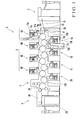
- a sheet-fed offset rotary printing press 1 comprises a feed device 2 which feeds a sheet, a printing unit 3 which prints on the sheet fed from the feed device 2, a coating unit 4 which coats the obverse and reverse surfaces of the sheet printed by the printing unit 3 with varnish, and a delivery unit 5 which delivers the sheet coated by the coating unit 4.
- the printing unit 3 comprises four obverse surface printing units 6A to 6D which correspond to four different colors, and four reverse surface printing units 7A to 7D which correspond to four different colors.
- Each of the obverse surface printing units 6A to 6D includes a double-sized diameter impression cylinder 10a provided with grippers on its outer surface which grip the sheet, a blanket cylinder 11a which is located above the impression cylinder 10a to oppose it, a plate cylinder 12a which is located above the blanket cylinder 11a to oppose it, an inking device 13a which supplies ink to the plate cylinder 12a, and a dampening device 14a which supplies water to the plate cylinder 12a.
- Each of the reverse surface printing units 7A to 7D includes a double-sized diameter impression cylinder 10b provided with grippers on its outer surface which grip the sheet, a blanket cylinder 11b which is located under the impression cylinder 10b to oppose it, a plate cylinder 12b which is located under the blanket cylinder 11b to oppose it, an inking device 13b which supplies ink to the plate cylinder 12b, and a dampening device 14b which supplies water to the plate cylinder 12b.
- the leading edge of the sheet fed from the feed device 2 onto a feeder board 15 is gripped by a swing arm shaft pregripper 16 and supplied to the obverse surface printing unit 6A through a transfer cylinder 17.
- the sheet fed to the obverse surface printing unit 6A is gripping-changed to the grippers of the impression cylinder 10a and printed with the first color on its obverse surface as it passes through the opposing point of the impression cylinder 10a and blanket cylinder 11a.
- the sheet printed with the first color on its obverse surface is gripping-changed to the impression cylinder 10b of the first reverse surface printing unit 7A and printed with the first color on its reverse surface as it passes through the opposing point of the impression cylinder 10b and blanket cylinder 11b.
- the sheet which is printed with four colors on its obverse and reverse surfaces by the obverse surface printing units 6B to 6D and reverse surface printing units 7B to 7D is coated with varnish on its obverse and reverse surfaces by the coating unit 4, as will be described later.
- the varnish-coated sheet is gripping-changed to the delivery grippers (not shown) of a delivery chain 19 of the delivery unit 5, is conveyed by the delivery chain 19, and falls on a delivery pile 20 and is stacked there.
- a sensor 22 is arranged at the downstream front end in the sheet convey direction of the feeder board 15 and detects the presence/absence of a sheet on the feeder board 15.
- the coating unit 4 includes a blanket impression cylinder 24 serving as an impression cylinder which opposes the impression cylinder 10b of the reverse surface printing unit 7D, a first varnish coating device 25 which coats the reverse surface of the printed sheet, and a second varnish coating device 26 which coats the obverse surface of the printed sheet.
- the first varnish coating device 25 includes a first varnish film forming cylinder 27, first anilox roller 28 (varnish supply means), and a chamber coater 29.
- the first varnish film forming cylinder 27 serves as a varnish supply cylinder which opposes the blanket impression cylinder 24 upstream in the sheet convey direction of the opposing point of the blanket impression cylinder 24 and impression cylinder 10b.
- the first anilox roller 28 opposes the first varnish film forming cylinder 27.
- the chamber coater 29 supplies the varnish to the first anilox roller 28.
- the varnish supplied from the chamber coater 29 to the first anilox roller 28 spreads to the outer surface of the blanket impression cylinder 24 through the first varnish film forming cylinder 27.
- the second varnish coating means 26 includes a blanket cylinder 30, second varnish film forming cylinder 31, second anilox roller 32 (varnish supply means), and chamber coater 33.
- the blanket cylinder 30 serves as a varnish supply cylinder which opposes the blanket impression cylinder 24 downstream in the sheet convey direction of the opposing point of the blanket impression cylinder 24 and impression cylinder 10b.
- the second varnish film forming cylinder 31 serves as a varnish supply cylinder which opposes the blanket cylinder 30.
- the second anilox roller 32 serves as a varnish supply means which opposes the second varnish film forming cylinder 31.
- the chamber coater 33 supplies the-varnish to the-second anilox roller 32.
- the varnish supplied from the chamber coater 33 to the anilox roller 32 spreads to the blanket cylinder 30 through the varnish film forming cylinder 31 and coats the obverse surface of the printed sheet which passes through the opposing point of the blanket cylinder 30 and blanket impression cylinder 24.
- the varnish spreading from the varnish film forming cylinder 27 of the varnish coating device 25 to the outer surface of the blanket impression cylinder 24 coats the reverse surface of the printed sheet by the printing pressure of the blanket cylinder 30.
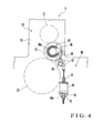
- a cylinder throw on/off mechanism which throws on/off the varnish film forming cylinder 27 in the varnish coating device 25 and a cylinder throw on/off mechanism which throws on/off the blanket cylinder 30 in the varnish coating device 26 will be described with reference to Fig. 4.
- a cylinder throw on/off mechanism 40 which throws on/off the blanket cylinder 30 will only be described in detail, and the cylinder throw on/off mechanism which throws on/off the varnish film forming cylinder 27 will be described briefly when necessary.
- the two end shafts of each of the blanket impression cylinder 24 and varnish-film forming cylinder 31 are rotatably, axially supported by a pair of frames 39, which oppose each other at a predetermined gap, through bearings (not shown).
- Two end shafts 30a of the blanket cylinder 30 are rotatably, axially supported by eccentric bearings 41 (to be described later) fitted on the pair of frames 39.
- a stud 42 projects outwardly from one frame 39 to be close to the corresponding end shaft of the blanket impression cylinder 24.
- a bracket 43 is supported by the stud 42.
- a stepping motor 44 serving as a driving device is fixed to the bracket 43 such that its driving rod 45 stands vertically.
- the driving rod 45 having a threaded portion threadably engaging with the nut 44a vertically moves.
- the two ends of a lever shaft 46 are axially supported by a pair of frames 39.
- a connecting lever 47 having an L shape when seen from the front is axially mounted on the projecting portion of the lever shaft 46.
- Each eccentric bearing 41 comprises a housing (not shown) which is fitted in the bearing hole of the corresponding frame 39, an outer ring (not shown) which fits with the housing through a needle roller, and an inner ring (not shown) which is rotatably fitted in the outer ring through a conical roller.
- a bearing lever 48 fixed to the outer ring of the eccentric bearing 41 is connected to the connecting lever 47 through a rod 49.
- the axis of the inner surface of the inner ring which forms the eccentric bearing 41 and the axis of the outer surface of the outer ring of the eccentric bearing 41 are eccentric from each other by a predetermined distance.
- the axis of the inner surface of the inner ring moves about the axis of the outer surface of the outer ring as the center. Consequently, a gap is formed between the blanket cylinder 30 and blanket impression cylinder 24, and the blanket cylinder 30 is thrown off the blanket impression cylinder 24.
- the outer surfaces of the blanket cylinder 30 and varnish film forming cylinder 31 are kept in contact with each other.
- a cylinder throw on/off mechanism which throws on/off the anilox roller 28 of the varnish coating device 25 and a cylinder throw on/off mechanism which throws on/off the anilox roller 32 of the varnish coating device 26 will be described with reference to Fig. 2.
- the anilox roller 28 is pivotally supported by the frame 39 through an eccentric bearing 28a, and a bearing lever 53A is fixed to the outer ring of the eccentric bearing 28a.
- the swing end of the bearing lever 53A is pivotally mounted on a rod 52A of an air cylinder 51A pivotally mounted on the frame 39.
- the anilox roller 32 is pivotally supported by the frame 39 through an eccentric bearing 32a, and a bearing lever 53B is fixed to the outer ring of the eccentric bearing 32a.
- the swing end of the bearing lever 53B is pivotally mounted on a rod 52B of an air cylinder 51B pivotally mounted on the frame 39.
- the eccentric bearing 32a pivots clockwise in Fig. 2 through the bearing lever 53B.
- a gap is formed between the anilox roller 32 and second varnish film forming cylinder 31, and the anilox roller 32 is thrown off the varnish film forming cylinder 31.
- the eccentric bearing 32a pivots counterclockwise in Fig. 2 through the bearing lever 53B.
- the anilox roller 32 comes into contact with the varnish film forming cylinder 31 and is thrown on the varnish film forming cylinder 31.
- the printing device described above is not particularly different from the coating device of a known sheet-fed offset rotary printing press.
- a planet gear train 60 which switches drive transmission to the anilox rollers 28 and 32 will be described with reference to Figs. 6A and 6B.
- the planet gear train 60 mainly comprises a ring-like internal gear 61, sun gear 62, four planet gears 63, and a pair of carriers 64A and 64B.
- the internal gear 61 is driven to rotate by a printing press motor 82 (Fig. 8) serving as the first driving source.
- the sun gear 62 is coaxially arranged with the internal gear 61 and driven to rotate by an anilox roller motor 84 serving as the second driving source.
- the four planet gears 63 are arranged between the sun gear 62 and internal gear 61 and mesh with them.
- the pair of carriers 64A and 64B rotatably sandwich the planet gears 63 and rotate around the sun gear 62 when either one of the internal gear 61 and sun gear 62 rotates.
- a plurality of insertion through holes 61a are equidistantly formed in the side surface of the ring portion of the internal gear 61 in the circumferential direction.
- the sun gear 62 has a fitting hole 62a with a D-cut section at its center.
- Each planet gear 63 has a loose insertion hole 63a at its center.
- the carrier 64A has an internal gear 65 extending through its center, and four partitioning projections 67 on the rear surface of its peripheral portion.
- the partitioning projections 67 respectively have projecting bosses 68. Support recesses (not shown) are formed between the adjacent partitioning projections 67.
- the carrier 64B has a fitting hole 70 at its center, and four support recesses 71 in the surface of its peripheral portion which opposes the carrier 64A.
- Four partitioning projections 72 respectively having support recesses 73 are formed between the adjacent support recesses 71.
- the four pairs of planet rollers 74A and 74B respectively have flanges 75, and loose insertion holes 76 at their centers.
- the sun gear 62 meshes with the respective planet gears 63, and the internal gear 61 meshes with the four planet gears 63 to surround them.
- the planet gear train 60 is formed.
- the relationship among the numbers of teeth of the three gears 61, 62, and 63 is set such that when the printing press motor 82 rotates the anilox rollers 28 and 32 in a manner to be described later, the peripheral speeds of the anilox rollers 28 and 32 become equal to those of the varnish film forming cylinders 27 and 31.
- the relationship among the numbers of teeth of the three gears 61, 62, and 63 is set such that when both the printing press motor 82 and anilox roller motor 84 are driven simultaneously, rotation of the anilox roller 28 will not stop.
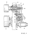
- the rotary drive transmitting apparatuses of the anilox rollers 28 and 32 will be described with reference to Figs. 5 to 8. These rotary drive transmitting apparatuses have the same structures. Thus, only the rotary drive transmitting apparatus of the anilox roller 28 will be described in detail, and that of the anilox roller 32 will be briefly described when necessary.
- a driving gear 81 is rotatably supported by an end shaft 28b, which projects outward from the frame 39, of the anilox roller 28, and is driven to rotate by the printing press motor 82 (see Fig. 8).
- a roller gear 83 is also axially mounted on the end shaft 28b of the anilox roller 28.
- the anilox roller motor 84 having an output shaft 84a is attached outside the frame 39.
- a motor gear 85 axially mounted on the output shaft 84a meshes with an intermediate-gear 86 rotatably supported by the frame 39.
- a shaft 87 has one end with a key groove in its circumferential portion and the other end with a D-cut section.
- the intermediate gear 86 is axially mounted on one end of the shaft 87 through a key, and the fitting hole 62a of the sun gear 62 of the planet gear train 60 is fitted on the other end of the shaft 87.
- the intermediate gear 86 integrally rotates with the sun gear 62 through the shaft 87.
- An intermediate gear 88 which meshes with the driving gear 81 is rotatably supported by a bearing member 89 attached to the frame 39.
- the intermediate gear 88 is attached to the internal gear 61 of the planet gear train 60 with screws 61b inserted in the insertion through holes 61a.
- a transmission gear 90 which meshes with the roller gear 83 is rotatably supported by a bearing member 91 attached to the frame 39.
- a shaft 92 has one end with a spline formed in its circumferential portion and the other end with a key groove in its circumferential portion.
- a small shaft 92a projects from the end face of the other end of the shaft 92.
- One end of the shaft 92 meshes with the internal gear 65 of the carrier 64A of the planet gear train 60.
- the transmission gear 90 is axially mounted on the other end of the shaft 92 through a key, as shown in Fig. 5.
- the transmission gear 90 rotates integrally with the carrier 64A through the shaft 92.
- the small shaft 92a of the shaft 92 is rotatably supported by a bearing member 93 attached to the frame 39.
- a controller 98 is connected to the sensor 22, the air cylinders 51A and 51B, the printing press motor 82, the anilox roller motor 84, a rotary encoder 95 which detects the rotational positions of the respective cylinders of the printing press, an operation start button 96, and an operation stop button 97.
- the controller 98 actuates the air cylinders 51A and 51B when, during printing, the last sheet is gripping-changed from the swing arm shaft pregripper 16 to the grippers of the transfer cylinder 17 and the sensor 22 detects no sheet.
- the anilox roller 28 is thrown off the varnish film forming cylinder 27, and the anilox roller 32 is thrown off the second varnish film forming cylinder 31.
- the controller 98 drives the anilox roller motor 84 and continuously drives the printing press motor 82. After that, when the rotary encoder 95 detects that the last sheet is delivered to the delivery unit 5, the controller 98 stops the driving operation of the printing press motor 82.
- the controller 98 drives the printing press motor 82 and anilox roller motor 84 simultaneously. After the last sheet is delivered to the delivery unit 5, when the printing press motor 82 stops driving, the controller 98 drives the anilox roller motor 84.
- the anilox roller motor 84 has two states, i.e., a driving state and non-driving state.
- the anilox roller motor 84 is always in the driving state.
- the controller 98 drives the anilox roller motor 84 at least when the printing press motor 82 is kept stopped.
- the controller 98 stops driving the anilox roller motor 84 and drives the printing press motor 82.
- a drive switching operation for the anilox rollers at the start of printing and at the end of printing of the roller rotary drive transmitting apparatus having the above arrangement will be described.
- a drive switching operation to the anilox rollers at the start of printing will be described.
- the operation start button 96 When the operation start button 96 is turned on, the air cylinders 51A and 51B are actuated, and the anilox roller 28 is separated from and thrown off the varnish film forming cylinder 27. Simultaneously, the anilox roller 32 is separated from and thrown off the frames 31.
- the anilox roller motor 84 is driven when the printing press motor 82 is kept stopped.
- the rotary driving operation of the anilox roller motor 84 is transmitted to the sun gear 62 of the planet gear train 60 through the motor gear 85 and intermediate gear 86.
- the rotation of the internal gear 61 of the planet gear train 60 which is connected to the driving gear 81 through the intermediate gear 88 is kept stopped.
- the printing press motor 82 when the printing press motor 82 is driven to start printing, the first sheet is fed from the feed device 2 to the feeder board 15 and detected by the sensor 22.
- the impression cylinders 10a of the respective printing units 6A to 6D and the impression cylinders 10b of the respective printing units 7A to 7D are thrown on, and the printing units 6A to 6D and 7A to 7D print on the obverse and reverse surfaces of the sheet.
- the controller 98 actuates the stepping motor 44 on the basis of a detection signal from the rotary encoder 95.
- the varnish film forming cylinder 27 is thrown on the blanket impression cylinder 24, and the blanket cylinder 30 is thrown on the blanket impression cylinder 24.
- the air cylinder 51A is actuated to throw the anilox roller 28 on the varnish film forming cylinder 27.
- the air cylinder 51B is actuated to throw the anilox roller 32 on the varnish film forming cylinder 31. Accordingly, the varnish which has been supplied from the chamber coater 29 to the anilox roller 28 is supplied to the varnish film forming cylinder 27. Simultaneously, the varnish which has been supplied from the chamber coater 33 to the anilox roller 32 is supplied to the blanket cylinder 30 through the varnish film forming cylinder 31.
- the controller 98 stops driving the anilox roller motor 84 simultaneously. Until the driving operation of the anilox roller motor 84 is stopped, the anilox roller motor 84 and printing press motor 82 are driven simultaneously. At this time, since the numbers of teeth of the three gears 61, 62, and 63 are set such that the carriers 64A and 64B do not stop rotation when the internal gear 61 and sun gear 62 rotate simultaneously, the anilox rollers 28 and 32 continue rotation through the carrier 64A.
- the carrier 64A rotates around the sun gear 62.
- the transmission gear 90 which is attached to the carrier 64A rotates, and the anilox rollers 28 and 32 rotate through the roller gear 83 which meshes with the transmission gear 90. Accordingly, the anilox rollers 28 and 32 are driven by the printing press motor 82.
- the relationship among the numbers of teeth of the three gears 61, 62, and 63 of the planet gear train 60 is set such that when the anilox roller 28 is rotated by the printing press motor 82, the peripheral speed of the anilox roller 28 (32) becomes equal to that of the varnish film forming cylinder 27 (31).
- the varnish film thickness is not fluctuated by relative rotational fluctuation between the anilox rollers 28 and 32 and varnish film forming cylinders 27 and 31.
- the controller 98 drives the anilox roller motor 84
- the rotation of the motor 84 is transmitted to the sun gear 62 of the planet gear train 60 through the motor 85 and intermediate gear 86, and the sun gear 62 starts rotation.
- the internal gear 61 of the planet gear train 60 which is connected to the driving gear 81 through the intermediate gear 88 also rotates.
- the numbers of teeth of the internal gear 61, sun gear 62, and planet gears 63 are set such that when the internal gear 61 and sun gear 62 rotate simultaneously, the carriers 64A and 64B will not stop rotation. Therefore, the anilox rollers 28 and 32 which are impression throw-off through the carrier 64A continue rotation, so that the varnish on the anilox rollers 28 and 32 is prevented from drying.
- the second embodiment of the present invention will be described with reference to Fig. 9.
- the second embodiment is different from the first embodiment in that a voltage value detector 99 is provided in place of the sensor 22 and rotary encoder 95 shown in Fig. 8, and that the air cylinders 51A and 51B are omitted.
- the voltage detector 99 detects the voltage value of a printing press motor 82.
- a controller 100 starts driving an anilox roller motor 84 when the detection value of the voltage value detector 99 is zero, and stops driving the anilox roller motor 84 when the detection value of the voltage detector 99 exceeds zero. More specifically, the controller 100 controls to drive the anilox roller motor 84 when the printing press motor 82 is kept stopped, and to stop driving the anilox roller motor 84 when the printing press motor 82 keeps driving. In other words, unlike the first embodiment, the printing press motor 82 and anilox roller motor 84 are not driven simultaneously.
- the chamber coaters 29 and 33 supply the varnish as the varnish coating units to the anilox rollers 28 to 32.
- the varnish may be coated by a fountain roller having an outer surface partly dipped in the varnish in a varnish pan.
- the anilox roller in the coater device has been described, the preset invention can also be applied to a dampening form roller in a dampening device.
- the coating device has been described as a coating unit arranged between the printing unit 3 and delivery unit 5 of the sheet-fed offset rotary printing press, the coating unit may be arranged in an independent varnish coater or the like.
Landscapes
- Engineering & Computer Science (AREA)
- Mechanical Engineering (AREA)
- Rotary Presses (AREA)
- Structure Of Transmissions (AREA)
Applications Claiming Priority (1)
| Application Number | Priority Date | Filing Date | Title |
|---|---|---|---|
| JP2005065374A JP2006250202A (ja) | 2005-03-09 | 2005-03-09 | ローラの回転駆動伝達装置 |
Publications (2)
| Publication Number | Publication Date |
|---|---|
| EP1700697A2 true EP1700697A2 (de) | 2006-09-13 |
| EP1700697A3 EP1700697A3 (de) | 2007-06-27 |
Family
ID=36655039
Family Applications (1)
| Application Number | Title | Priority Date | Filing Date |
|---|---|---|---|
| EP06004532A Withdrawn EP1700697A3 (de) | 2005-03-09 | 2006-03-06 | Rollen- Kraftübertragungsvorrichtung |
Country Status (4)
| Country | Link |
|---|---|
| US (1) | US20060201352A1 (de) |
| EP (1) | EP1700697A3 (de) |
| JP (1) | JP2006250202A (de) |
| CN (1) | CN100504109C (de) |
Cited By (2)
| Publication number | Priority date | Publication date | Assignee | Title |
|---|---|---|---|---|
| EP1961566A3 (de) * | 2007-02-21 | 2012-06-20 | Komori Corporation | Vorrichtung zur Bogenverarbeitung |
| TWI571297B (zh) * | 2014-12-29 | 2017-02-21 | 建國科技大學 | 柑橘類精油冷壓萃取機 |
Families Citing this family (6)
| Publication number | Priority date | Publication date | Assignee | Title |
|---|---|---|---|---|
| US7463004B2 (en) * | 2006-07-10 | 2008-12-09 | Xerox Corporation | Planetary dual stepper drives |
| US8210102B2 (en) | 2007-01-25 | 2012-07-03 | Komori Corporation | Switch-over processing method and apparatus |
| JP6148247B2 (ja) * | 2012-10-22 | 2017-06-14 | 株式会社小森コーポレーション | 組合せ印刷機 |
| CN103101290B (zh) * | 2013-01-23 | 2016-01-13 | 深圳市博泰印刷设备有限公司 | 间歇式柔印设备 |
| JP6349197B2 (ja) * | 2014-08-08 | 2018-06-27 | 株式会社小森コーポレーション | 液体転写装置 |
| CN109465144B (zh) * | 2016-12-13 | 2020-09-15 | 日照斯诺尔建材检测有限公司 | 一种空气消毒片药层涂覆装置 |
Citations (1)
| Publication number | Priority date | Publication date | Assignee | Title |
|---|---|---|---|---|
| US4569306A (en) | 1983-02-03 | 1986-02-11 | Komori Printing Machinery Co., Ltd. | Varnish coater for printed product |
Family Cites Families (19)
| Publication number | Priority date | Publication date | Assignee | Title |
|---|---|---|---|---|
| GB1214436A (en) * | 1969-07-29 | 1970-12-02 | Planeta Veb Druckmasch Werke | Improvements in or relating to rotary sheet printing machine |
| FR2261452A1 (en) * | 1974-02-20 | 1975-09-12 | Durdilly Jacques | Epicyclic gear train for sutter roller - has manual or automatic drives for satellite carrier or sun wheel |
| FR2540058A1 (fr) * | 1983-01-28 | 1984-08-03 | Soma Europ Transmissions | Groupe de commande d'entrainement et de commande de direction pour engin a organes de roulement droite-gauche non directeurs |
| JPS63180753A (ja) * | 1987-01-19 | 1988-07-25 | Koji Onuma | 変速駆動装置 |
| US4953461A (en) * | 1988-05-20 | 1990-09-04 | Harris Graphics Corporation | System for continuously rotating plate a blanket cylinders at relatively different surface speeds |
| JPH07108101B2 (ja) * | 1989-02-28 | 1995-11-15 | オ−クマ株式会社 | リニアアクチュエータ駆動制御装置 |
| DE4013462A1 (de) * | 1990-04-27 | 1991-11-07 | Heidelberger Druckmasch Ag | Vorrichtung zum lackieren von bedruckten bogen an druckmaschinen |
| DE4132250A1 (de) * | 1991-09-27 | 1993-04-08 | Roland Man Druckmasch | Einrichtung zur umstellung auf schoen- oder schoen- und widerdruck an bogenrotationsdruckmaschinen |
| DE4322791B4 (de) * | 1993-07-08 | 2005-06-30 | Heidelberger Druckmaschinen Ag | Rotationsdruckmaschine |
| DE19640649A1 (de) * | 1996-10-02 | 1998-04-16 | Roland Man Druckmasch | Antrieb für eine Bogendruckmaschine |
| US5950502A (en) * | 1998-03-16 | 1999-09-14 | Genovese; Vincent | Orthogonal differential drive |
| DE19943027C5 (de) * | 1998-10-28 | 2016-11-17 | Heidelberger Druckmaschinen Ag | Positioniervorrichtung in einer Druckmaschine |
| US6070529A (en) * | 1999-03-31 | 2000-06-06 | Stevens International, Inc. | Printing press with registration control |
| JP4318109B2 (ja) * | 1999-04-28 | 2009-08-19 | 株式会社ミヤコシ | フォーム印刷機における印刷部の紙送り速度調整装置 |
| US6289805B1 (en) * | 2000-02-08 | 2001-09-18 | Heidelberger Druckmaschinen Ag | Device and method for driving a printing cylinder |
| US6851368B2 (en) * | 2001-08-29 | 2005-02-08 | Heidelberger Druckmaschinen Ag | Rotary printing press having a switchable speed-change gear mechanism with plant gears |
| DE10144563A1 (de) * | 2001-09-11 | 2003-03-27 | Heidelberger Druckmasch Ag | Druckmaschine und Verfahren zum Betreiben eines Farbwerks |
| DE10306492B4 (de) * | 2002-03-21 | 2006-10-19 | Heidelberger Druckmaschinen Ag | Andrückvorrichtung einer Druck- oder Lackiermaschine |
| DE102004052112A1 (de) * | 2004-10-26 | 2006-04-27 | Man Roland Druckmaschinen Ag | Vorrichtung zum Antrieb einer Walze |
-
2005
- 2005-03-09 JP JP2005065374A patent/JP2006250202A/ja active Pending
-
2006
- 2006-03-06 US US11/369,585 patent/US20060201352A1/en not_active Abandoned
- 2006-03-06 EP EP06004532A patent/EP1700697A3/de not_active Withdrawn
- 2006-03-09 CN CNB2006100589810A patent/CN100504109C/zh not_active Expired - Fee Related
Patent Citations (1)
| Publication number | Priority date | Publication date | Assignee | Title |
|---|---|---|---|---|
| US4569306A (en) | 1983-02-03 | 1986-02-11 | Komori Printing Machinery Co., Ltd. | Varnish coater for printed product |
Cited By (2)
| Publication number | Priority date | Publication date | Assignee | Title |
|---|---|---|---|---|
| EP1961566A3 (de) * | 2007-02-21 | 2012-06-20 | Komori Corporation | Vorrichtung zur Bogenverarbeitung |
| TWI571297B (zh) * | 2014-12-29 | 2017-02-21 | 建國科技大學 | 柑橘類精油冷壓萃取機 |
Also Published As
| Publication number | Publication date |
|---|---|
| JP2006250202A (ja) | 2006-09-21 |
| US20060201352A1 (en) | 2006-09-14 |
| EP1700697A3 (de) | 2007-06-27 |
| CN100504109C (zh) | 2009-06-24 |
| CN1831371A (zh) | 2006-09-13 |
Similar Documents
| Publication | Publication Date | Title |
|---|---|---|
| US6050188A (en) | Sheet-fed rotary press | |
| EP0115854B1 (de) | Lackiervorrichtung für Druckerzeugnisse | |
| EP0115855A2 (de) | Lackiervorrichtung für Druckprodukte | |
| EP1700697A2 (de) | Rollen- Kraftübertragungsvorrichtung | |
| EP1743768B1 (de) | Druckmaschine mit einem bewegbaren Farbwerk | |
| US6634292B2 (en) | Printing press with means for connecting and disconnecting motors for oscillating roller | |
| US20130280411A1 (en) | Liquid transfer apparatus | |
| JP2000514738A (ja) | 多色枚葉紙印刷機 | |
| US6302018B1 (en) | Offset printer having power transmission shut off mechanism | |
| JP3156006U (ja) | 枚葉紙の両面に印刷するための枚葉紙オフセット印刷機 | |
| JP2000198262A (ja) | 孔版印刷装置 | |
| US20070245911A1 (en) | Drive for a Rotary Printing Press | |
| US20100095861A1 (en) | Printing press for printing on both sides of sheets | |
| US6647875B2 (en) | Roller structure in printing press | |
| US7096782B2 (en) | Driving apparatus in printing press | |
| JPH0415741B2 (de) | ||
| EP1516728B1 (de) | Zylindervorrichtung | |
| US20080092758A1 (en) | Stop position control method and apparatus of rotary stencil printing press | |
| US20130276656A1 (en) | Liquid transfer apparatus | |
| JP2003080677A (ja) | 輪転印刷機 | |
| JP2591668B2 (ja) | 両面刷枚葉印刷機の胴間すき間調整装置 | |
| US20070234913A1 (en) | Drive for a rotary printing press | |
| US6796229B2 (en) | Gear train for a machine for processing flat printing materials | |
| JPH03143634A (ja) | 枚葉印刷機 | |
| JP4669870B2 (ja) | オフセット印刷機 |
Legal Events
| Date | Code | Title | Description |
|---|---|---|---|
| PUAI | Public reference made under article 153(3) epc to a published international application that has entered the european phase |
Free format text: ORIGINAL CODE: 0009012 |
|
| AK | Designated contracting states |
Kind code of ref document: A2 Designated state(s): AT BE BG CH CY CZ DE DK EE ES FI FR GB GR HU IE IS IT LI LT LU LV MC NL PL PT RO SE SI SK TR |
|
| AX | Request for extension of the european patent |
Extension state: AL BA HR MK YU |
|
| PUAL | Search report despatched |
Free format text: ORIGINAL CODE: 0009013 |
|
| AK | Designated contracting states |
Kind code of ref document: A3 Designated state(s): AT BE BG CH CY CZ DE DK EE ES FI FR GB GR HU IE IS IT LI LT LU LV MC NL PL PT RO SE SI SK TR |
|
| AX | Request for extension of the european patent |
Extension state: AL BA HR MK YU |
|
| 17P | Request for examination filed |
Effective date: 20071221 |
|
| AKX | Designation fees paid |
Designated state(s): AT BE BG CH CY CZ DE DK EE ES FI FR GB GR HU IE IS IT LI LT LU LV MC NL PL PT RO SE SI SK TR |
|
| 17Q | First examination report despatched |
Effective date: 20080228 |
|
| STAA | Information on the status of an ep patent application or granted ep patent |
Free format text: STATUS: THE APPLICATION IS DEEMED TO BE WITHDRAWN |
|
| 18D | Application deemed to be withdrawn |
Effective date: 20101001 |