EP1701080B1 - Améliorations des ou en rapport avec des tuyaux - Google Patents
Améliorations des ou en rapport avec des tuyaux Download PDFInfo
- Publication number
- EP1701080B1 EP1701080B1 EP06250969A EP06250969A EP1701080B1 EP 1701080 B1 EP1701080 B1 EP 1701080B1 EP 06250969 A EP06250969 A EP 06250969A EP 06250969 A EP06250969 A EP 06250969A EP 1701080 B1 EP1701080 B1 EP 1701080B1
- Authority
- EP
- European Patent Office
- Prior art keywords
- throughway
- tube
- collet
- ring
- cap
- Prior art date
- Legal status (The legal status is an assumption and is not a legal conclusion. Google has not performed a legal analysis and makes no representation as to the accuracy of the status listed.)
- Expired - Lifetime
Links
Images


Classifications
-
- F—MECHANICAL ENGINEERING; LIGHTING; HEATING; WEAPONS; BLASTING
- F16—ENGINEERING ELEMENTS AND UNITS; GENERAL MEASURES FOR PRODUCING AND MAINTAINING EFFECTIVE FUNCTIONING OF MACHINES OR INSTALLATIONS; THERMAL INSULATION IN GENERAL
- F16L—PIPES; JOINTS OR FITTINGS FOR PIPES; SUPPORTS FOR PIPES, CABLES OR PROTECTIVE TUBING; MEANS FOR THERMAL INSULATION IN GENERAL
- F16L19/00—Joints in which sealing surfaces are pressed together by means of a member, e.g. a swivel nut, screwed on, or into, one of the joint parts
- F16L19/08—Joints in which sealing surfaces are pressed together by means of a member, e.g. a swivel nut, screwed on, or into, one of the joint parts with metal rings which bite into the wall of the pipe
- F16L19/083—Joints in which sealing surfaces are pressed together by means of a member, e.g. a swivel nut, screwed on, or into, one of the joint parts with metal rings which bite into the wall of the pipe the longitudinal cross-section of the ring not being modified during clamping
- F16L19/086—Joints in which sealing surfaces are pressed together by means of a member, e.g. a swivel nut, screwed on, or into, one of the joint parts with metal rings which bite into the wall of the pipe the longitudinal cross-section of the ring not being modified during clamping with additional sealing means
-
- F—MECHANICAL ENGINEERING; LIGHTING; HEATING; WEAPONS; BLASTING
- F16—ENGINEERING ELEMENTS AND UNITS; GENERAL MEASURES FOR PRODUCING AND MAINTAINING EFFECTIVE FUNCTIONING OF MACHINES OR INSTALLATIONS; THERMAL INSULATION IN GENERAL
- F16L—PIPES; JOINTS OR FITTINGS FOR PIPES; SUPPORTS FOR PIPES, CABLES OR PROTECTIVE TUBING; MEANS FOR THERMAL INSULATION IN GENERAL
- F16L19/00—Joints in which sealing surfaces are pressed together by means of a member, e.g. a swivel nut, screwed on, or into, one of the joint parts
- F16L19/005—Joints in which sealing surfaces are pressed together by means of a member, e.g. a swivel nut, screwed on, or into, one of the joint parts comprising locking means for the threaded member
-
- F—MECHANICAL ENGINEERING; LIGHTING; HEATING; WEAPONS; BLASTING
- F16—ENGINEERING ELEMENTS AND UNITS; GENERAL MEASURES FOR PRODUCING AND MAINTAINING EFFECTIVE FUNCTIONING OF MACHINES OR INSTALLATIONS; THERMAL INSULATION IN GENERAL
- F16L—PIPES; JOINTS OR FITTINGS FOR PIPES; SUPPORTS FOR PIPES, CABLES OR PROTECTIVE TUBING; MEANS FOR THERMAL INSULATION IN GENERAL
- F16L37/00—Couplings of the quick-acting type
- F16L37/08—Couplings of the quick-acting type in which the connection between abutting or axially overlapping ends is maintained by locking members
- F16L37/084—Couplings of the quick-acting type in which the connection between abutting or axially overlapping ends is maintained by locking members combined with automatic locking
- F16L37/092—Couplings of the quick-acting type in which the connection between abutting or axially overlapping ends is maintained by locking members combined with automatic locking by means of elements wedged between the pipe and the frusto-conical surface of the body of the connector
- F16L37/0925—Couplings of the quick-acting type in which the connection between abutting or axially overlapping ends is maintained by locking members combined with automatic locking by means of elements wedged between the pipe and the frusto-conical surface of the body of the connector with rings which bite into the wall of the pipe
-
- F—MECHANICAL ENGINEERING; LIGHTING; HEATING; WEAPONS; BLASTING
- F16—ENGINEERING ELEMENTS AND UNITS; GENERAL MEASURES FOR PRODUCING AND MAINTAINING EFFECTIVE FUNCTIONING OF MACHINES OR INSTALLATIONS; THERMAL INSULATION IN GENERAL
- F16L—PIPES; JOINTS OR FITTINGS FOR PIPES; SUPPORTS FOR PIPES, CABLES OR PROTECTIVE TUBING; MEANS FOR THERMAL INSULATION IN GENERAL
- F16L37/00—Couplings of the quick-acting type
- F16L37/08—Couplings of the quick-acting type in which the connection between abutting or axially overlapping ends is maintained by locking members
- F16L37/084—Couplings of the quick-acting type in which the connection between abutting or axially overlapping ends is maintained by locking members combined with automatic locking
- F16L37/092—Couplings of the quick-acting type in which the connection between abutting or axially overlapping ends is maintained by locking members combined with automatic locking by means of elements wedged between the pipe and the frusto-conical surface of the body of the connector
- F16L37/0927—Couplings of the quick-acting type in which the connection between abutting or axially overlapping ends is maintained by locking members combined with automatic locking by means of elements wedged between the pipe and the frusto-conical surface of the body of the connector the wedge element being axially displaceable for releasing the coupling
Definitions
- This invention relates to tube couplings.
- UK-A-1520742 discloses a "Speedfit" connector comprising a coupling body with a throughway open at one end and a tapered cam surface in the open end to receive a collet for locking a tube in the coupling.
- the collet is compressed against the tube by a slight withdrawal of the tube/collet from the coupling body which locks the tube in the coupling body.
- the collet can be depressed into the body to release the tube when required.
- UK-A-2167147 discloses a "SuperSeal” connector which is a modification of the "Speedfit” connector and has a separate sleeve screwed into the open end of the coupling body in which the tapered cam is formed. By screwing the sleeve into the coupling body the gripping action of the collet on the tube is increased. Also the collet becomes locked up in the coupling body and cannot be depressed to release the tube. The tube is then permanently locked in the coupling body.
- EP-A-0945662 discloses a tube coupling having both "Speedfit” and SuperSeal" modes of operation. More particularly the coupling comprises a coupling body having a throughway open at one end to receive an end portion of a tube and having an internal cam surface tapering towards the open end in which a collet is located for locking the tube in the coupling body by engagement with the tapered cam surface and having stop means to limit entry of the collet into the throughway.
- the coupling body has a main portion, the throughway of which receives the end of the tube and contains said stop means to limit insertion of the collet and an end cap in screw threaded engagement with the main body. The end cap provides said open end to the throughway and the tapered cam surface.
- Indexing means are provided between the end cap and the main body to define different positions of rotation of adjustment in the first of which the tube can be inserted in and by depressing the collet into the coupling body, released in the coupling body (i.e. "Speedfit” mode) and in the second of which the collet is engaged with the stop means to prevent the collet being depressed into the coupling body to release the tube (i.e. "SuperSeal” mode).
- EP-A-1398559 discloses a tube coupling comprising a coupling body having a throughway open at one end to receive a tube, an end cap in screw-threaded engagement with the coupling body to move between initial and advanced positions along the coupling body and having an opening for the tube and an internal cam surface tapering towards the tube opening, a collet in the end cap engaging the cam surface to lock a tube in the cap with movement of the collet outwardly of the cap and to release the tube when depressed inwardly of the cap, and stop means in the coupling body to limit movement of the collet inwardly of the end cap, the initial position of the end cap on the coupling body allowing a tube to be inserted and locked in the end cap by the collet and to be released by depressing the collet inwardly of the cap and the advanced position of the end cap holding the collet adjacent the stop means in the coupling body to prevent release of the tube; wherein detent means are provided acting between the cap and coupling body to provide resistance to movement
- This invention provides a tube coupling comprising a coupling body having an open ended throughway to receive a tube, an annular shoulder in the throughway facing the open end of the throughway, an 'O' ring seal for sealing with a tube located against the annular shoulder in the throughway, a collet located in the open end of the throughway for locking a tube in the throughway, the collet having a head projecting out of the open end of the throughway and resilient arms extending into the throughway, the throughway having a cam surface tapered towards the open end of the throughway and located between the annular shoulder and open end with which the ends of the arms are engagable to force the arms inwardly with movement of the collet outwardly of the throughway into gripping engagement with a tube extending through the collet into the throughway, and a ring disposed between the collet and 'O' ring seal, the side of the ring adjacent the collet having a ramp around its inner periphery to engage between the ends of the
- side of the ring adjacent the 'O' ring may also formed with a ramp around its inner periphery to engage the inner side of the 'O' ring seal and prevent the 'O' ring seal from being forced passed the shoulder in the coupling body into the throughway beyond the shoulder.
- the sides of the ring including the projecting ramps are symmetrical to either side of the ring.
- the ring may be of rectangular cross-section with the ramp or ramps formed integrally on one or both sides of the ring adjacent the inner periphery of the ring, the ramp or ramps facing outwardly of the ring.
- the throughway may have a further annular shoulder encircling the throughway disposed beyond the first annular shoulder from the open end of the throughway with which an end of a tube inserted into the coupling body is engageable.
- the coupling body may comprise a main body portion containing the first annular shoulder, O ring seal and ring and an end cap in screw threaded engagement with the main portion of the coupling body to enable the cap to be screwed on or off the main body portion, the cap containing said open end for the throughway, tapered cam surface and collet having resilient arms which engage with the taper cam surface in the cap.
- detent means may be provided acting between the cap and main body portion of the coupling body to resist the cap being withdrawn fully from the coupling body whilst allowing the cap to be screwed onto the coupling body and screwed off the coupling body by a limited distance.
- the detent means may comprise an integral annular diaphragm formed on one of the coupling body end cap engageable in slots formed in the other of the main body portion and cap, the diaphragm allowing the cap to be screwed onto and off the coupling body within the range of movement permitted by the slot.
- the depth of the slot reduces to one side of the slot to increase the pressure on the flexible diaphragm as the diaphragm moves to the reduced depth side of the slot to increase resistance to the cap moving off the main body portion and vice versa.
- FIG. 1 of the drawings there is shown a moulded plastics tube coupling indicated generally by reference numeral 10 having a throughway 11 open at one end 12 to receive an end portion of a tube 13.
- the coupling comprises a main body 10a and an end cap 10b screwed onto the main body as described below.
- the throughway in the main body has a first increase in diameter at a step 14 to provide an enlarged bore 15 in which the end of the tube 13 is a close sliding fit with the end of the tube engaging the step 14.
- the throughway has a further increase in diameter at a step 16 to form a further enlarged bore 17 in which an 'O' ring seal 18 is located against the step followed by a spacer washer or compression ring 19.
- a collet indicated at 25 is mounted in the open end of the coupling body comprising an annular member 26 and resilient arms 27 projecting from the annular member into the throughway of the coupling body and terminating in heads 28.
- the heads of the collet engage in a tapered cam surface 29 formed in the throughway and converging towards the end of the coupling body to be compressed by the cam surface against the tube 13 to lock the tube in the coupling body.
- the spacer washer or compression ring 19 is of rectangular cross-section and has shallow outwardly facing ramps 19a, 19b formed around its inner periphery.
- the ramp adjacent the heads of the collet can engage under the heads when the collet is depressed into the coupling body to assist in releasing the grip of the collet arms with the tube passing through the collet. This is of particular significant in the case where the tube is of a relatively soft material and the teeth on the collet heads bite into the surface of the tube and do not automatically release from the surface.
- the ramp 19b on the ring 19 adjacent the O ring seal engages the O ring seal on its inner side and will act to prevent the seal being forced over the shoulder with which it engages into the throughway in the coupling body.
- the main body 10a has an external screw-threaded section 20 extending from one end of the body followed by a reduced diameter plain section 21 in which a detent is formed as described later and followed in turn by an integral encircling radial flange 22.
- the flange 22 has an abutment face 23 to provide an end stop for the cap when the latter is fully screwed onto the coupling body as described below.
- the end cap 10b of the coupling body encircles the main body and has an internal feature for engaging with the detent on the main body portion again as described later.
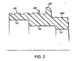
- FIG. 2 of the drawings is a cross-sectional view through part of the main body portion 10a.
- an upstanding annular flexible diaphragm 30 formed integrally with the body.
- the diaphragm forms part of the detent arrangement referred to above for engaging with and locking the cap on the body as described later.
- the end cap 10b is shown partially screwed onto the body to an initial position in which the collet in the cap receives and holds a tube in the coupling body in the "Speedfit" manner. That is to say, the tube is locked in the coupling body but can be released by depressing the collet into the coupling body to release the gripping engagement of the collet with the tube and allow the tube to be withdrawn.
- the end cap 10a has a mouth 31 with a lip around the inner periphery of the mouth.
- the inner side 34 of the end cap has an encircling slot 35 adjacent the mouth, in which the annular diaphragm 30 is snap engageable.
- the mouth of the cap has a bevelled entry indicated at 36 to assist in deforming the diaphragm inwardly as the cap is screwed onto the body and the diaphragm is forced through the mouth of the cap.
- the diameter of the lip at the mouth of the cap at the entry is less than the diameter of the diaphragm but is slightly greater than the rest of the inner diameter of the cap to facilitate entry of the diaphragm into the slot.
- Screwing the cap onto the body causes the diaphragm to snap into the slot 35 at the end nearest the mouth 31 of the cap.
- the cap is then located in the first "Speedfit" position referred to above.
- the bottom wall 37 of the slot is tapered to reduce in diameter towards the open end of the cap so that the diaphragm is held bent over towards the side of the slot adjacent the mouth of the slot.
- the diaphragm is trapped in the corner formed between the bottom wall of the slot and the side wall of the slot when the cap is rotated in a direction to withdraw from the main body to prevent withdrawal of the cap from the main body portion beyond the first position.
- the diaphragm rides up the tapering undercut of the bottom wall of the slot in the cap relaxing the diaphragm slightly, and therefore reducing the resistance to rotation of the cap.
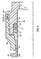
- the cap can then be screwed onto the body until it engages the upstanding end flange 22 of the coupling body as indicated in Figure 4 in which the cap is in the second or "SuperSeal" position.
- the collet is then held in engagement with the end stop in the coupling body and cannot be depressed to allow a tube to be released from the coupling body.
- the arrangement thus provides a tube coupling body which is readily assembled and which provides both "Speedfit” and “SuperSeal” functions without unduly stressing the components of the body.
- This design can also be used on metal coupling bodies or rigid plastic coupling bodies in which case the flexible diaphragm could be moulded on a separate split ring which is assembled into a groove or recess on the body between the thread and the large flange so that the detent engages in the slot on the cap.
- the separate split ring could be mounted in the cap with the flexible diaphragm projecting radially inwardly to engage in a slot in the main body portion.
- the slot in the body portion would be located between the thread and the large flange. Again, the slot in the body could be tapered in diameter.
- the diaphragm could be interrupted once or several times to allow for tooling or to allow the diaphragm's resilient/flexible characteristics to be optimised.
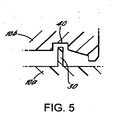
- an enlarged groove 30 is formed at the end of the slot remote from the open end of the cap as illustrated in Figure 5 .
Landscapes
- Engineering & Computer Science (AREA)
- General Engineering & Computer Science (AREA)
- Mechanical Engineering (AREA)
- Quick-Acting Or Multi-Walled Pipe Joints (AREA)
- Rigid Pipes And Flexible Pipes (AREA)
- Joints Allowing Movement (AREA)
Claims (10)
- Raccord de tuyau comprenant un corps de raccord comportant un passage à extrémité ouverte (11) pour recevoir un tuyau (13), un épaulement annulaire dans le passage (11) orienté vers l'extrémité ouverte du passage (11), un joint d'étanchéité torique (18) destiné à réaliser une étanchéité avec un tuyau situé contre l'épaulement annulaire dans le passage (11), une douille de serrage (25) située dans l'extrémité ouverte du passage (11) destinée au verrouillage d'un tuyau dans le passage (11), la douille de serrage comportant une tête (26) dépassant de l'extrémité ouverte du passage (11) et des bras élastiques (27) s'étendant dans le passage (11), le passage (11) comportant une surface de came (29) adjacente à ladite extrémité ouverte qui est inclinée vers l'extrémité ouverte du passage (11) avec laquelle les extrémités des bras (28) peuvent s'engager pour forcer les bras (27) vers l'intérieur avec un déplacement de la douille de serrage (25) vers l'extérieur du passage (11) pour un engagement par serrage avec un tuyau (13) s'étendant à travers la douille de serrage (25) dans le passage (11), et une bague (19) disposée dans le passage (11) entre la douille de serrage (25) et le joint d'étanchéité torique (18), un premier côté de la bague (19) adjacent à la douille de serrage (25) comportant une surface inclinée (19a) autour de sa périphérie intérieure pour recevoir les extrémités des bras (28) de la douille de serrage lorsque la douille de serrage (25) est enfoncée dans le passage pour libérer les bras (27) du tuyau (13) et permettre de cette manière une libération d'un tuyau (13) du corps de raccord, caractérisé en ce que l'autre côté de la bague présentant une surface inclinée (19b) autour de sa périphérie intérieure pour recevoir le joint d'étanchéité torique (18) afin de maintenir le joint d'étanchéité en alignement dans le passage (11) lorsque la douille de serrage (25) est enfoncée dans le passage (11).
- Raccord de tuyau selon la revendication 1, dans lequel la surface inclinée (19a) du côté de la bague (19) adjacent à la douille de serrage (25) est formée pour s'engager entre les bras de la douille de serrage et le tuyau traversant la douille de serrage pour soulever les bras (27) de la douille de serrage par rapport au tuyau lorsque la douille de serrage est enfoncée dans le passage (11).
- Raccord de tuyau selon la revendication 1, dans lequel la surface inclinée (19b) du côté de la bague adjacent au joint torique (18) est formée pour s'engager entre le joint torique (18) et le tuyau (13) pour aligner le joint d'étanchéité torique dans le passage (11) afin d'empêcher le joint torique (18) d'être forcé au-delà de l'épaulement dans le corps de raccord.
- Raccord de tuyau selon la revendication 1, dans lequel les côtés de la bague (19) comprenant les surfaces inclinées protubérantes (19a, 19b) sont symétriques de chaque côté de la bague.
- Raccord de tuyau selon la revendication 1, dans lequel la bague (19) est de section transversale rectangulaire avec la surface inclinée ou les surfaces inclinées (19a, 19b) formées intégralement sur un côté ou sur les deux côtés de la bague de façon adjacente à la périphérie intérieure de la bague, la surface inclinée ou les surfaces inclinées étant orientées vers l'extérieur de la bague.
- Raccord de tuyau selon la revendication 1, dans lequel le passage (11) comporte un autre épaulement annulaire (14) entourant le passage disposé au-delà du premier épaulement annulaire (16) depuis l'extrémité ouverte du passage, avec lequel une extrémité d'un tube (13) inséré dans le corps de raccord peut s'engager.
- Raccord de tuyau selon la revendication 1, dans lequel le corps de raccord comprend une partie de corps principale (10a) contenant le premier épaulement annulaire (16), le joint d'étanchéité torique (18) et la bague (19) et une coiffe d'extrémité (10b) en engagement vissé avec la partie principale du corps de raccord pour permettre à la coiffe (10b) d'être vissée ou dévissée sur la partie de corps principale (10a), la coiffe contenant ladite extrémité ouverte pour le passage (11), la surface de came inclinée (29) et la douille de serrage (25) comportant des bras élastiques (27) qui s'engagent avec la surface de came inclinée dans la coiffe.
- Raccord de tuyau selon la revendication 7, dans lequel un moyen d'arrêt est prévu pour agir entre la coiffe (10b) et la partie de corps principale (10a) du corps de raccord pour résister à la coiffe (10b) qui est retirée totalement du corps de raccord (10a) tout en permettant à la coiffe d'être vissée sur le corps de raccord et dévissée du corps de raccord d'une distance limitée.
- Raccord de tuyau selon la revendication 8, dans lequel le moyen d'arrêt comprend une membrane annulaire solidaire (30), formée sur l'un du corps de raccord (10a) et de la coiffe, pouvant s'engager dans des fentes (35) formées dans l'autre de la partie de corps principale (10b) et de la coiffe, la membrane permettant à la coiffe (10b) d'être vissée et dévissée du corps de raccord (10a) dans la plage de déplacement permise par la fente (35).
- Raccord de tuyau selon la revendication 9, dans lequel la face de fond de la fente (35) est inclinée vers un côté de la fente recevant la membrane souple (30) et fournit une résistance croissante au vissage de la coiffe (10b) sur le corps de raccord (10a).
Priority Applications (1)
| Application Number | Priority Date | Filing Date | Title |
|---|---|---|---|
| PL06250969T PL1701080T3 (pl) | 2005-03-09 | 2006-02-23 | Udoskonalenia złączek rurowych |
Applications Claiming Priority (1)
| Application Number | Priority Date | Filing Date | Title |
|---|---|---|---|
| GBGB0504899.6A GB0504899D0 (en) | 2005-03-09 | 2005-03-09 | Improvements in or relating to tube couplings |
Publications (2)
| Publication Number | Publication Date |
|---|---|
| EP1701080A1 EP1701080A1 (fr) | 2006-09-13 |
| EP1701080B1 true EP1701080B1 (fr) | 2008-05-21 |
Family
ID=34452097
Family Applications (1)
| Application Number | Title | Priority Date | Filing Date |
|---|---|---|---|
| EP06250969A Expired - Lifetime EP1701080B1 (fr) | 2005-03-09 | 2006-02-23 | Améliorations des ou en rapport avec des tuyaux |
Country Status (11)
| Country | Link |
|---|---|
| US (1) | US7425022B2 (fr) |
| EP (1) | EP1701080B1 (fr) |
| JP (1) | JP2006250356A (fr) |
| KR (1) | KR100886263B1 (fr) |
| AT (1) | ATE396358T1 (fr) |
| AU (1) | AU2006200838B2 (fr) |
| DE (1) | DE602006001220D1 (fr) |
| ES (1) | ES2306384T3 (fr) |
| GB (1) | GB0504899D0 (fr) |
| NZ (1) | NZ545610A (fr) |
| PL (1) | PL1701080T3 (fr) |
Cited By (1)
| Publication number | Priority date | Publication date | Assignee | Title |
|---|---|---|---|---|
| DE102023111894A1 (de) * | 2023-05-08 | 2024-11-14 | Grohe Ag | Steckverbinder zum Verbinden einer Kunststoffleitung mit einer Sanitärarmatur sowie Sanitärarmatur mit einem solchen Steckverbinder |
Families Citing this family (55)
| Publication number | Priority date | Publication date | Assignee | Title |
|---|---|---|---|---|
| US8579537B2 (en) * | 2006-07-05 | 2013-11-12 | Husqvarna Consumer Outdoor Products N.A., Inc. | Coupling arrangement |
| EP2126441A4 (fr) * | 2006-11-07 | 2013-01-02 | Yuk Nam Choi | Dispositifs de raccordement pour tuyaux |
| NO328491B1 (no) * | 2007-02-06 | 2010-03-01 | Raufoss Water & Gas As | Kobling |
| KR200447466Y1 (ko) * | 2007-04-04 | 2010-01-25 | 최육남 | 파이프 연결구 |
| GB0723646D0 (en) * | 2007-12-03 | 2008-01-16 | Guest John Int Ltd | Tube couplings |
| US7543858B1 (en) * | 2008-02-18 | 2009-06-09 | Hudson Wang | Water pipe connector |
| GB0809685D0 (en) * | 2008-05-28 | 2008-07-02 | Guest John Int Ltd | Improvements in or relating to tube couplings |
| US7900967B2 (en) * | 2008-09-16 | 2011-03-08 | GM Global Technology Operations LLC | Engine fitting and method of assembling vehicles |
| US20100171302A1 (en) * | 2009-01-05 | 2010-07-08 | Nibco Inc. | Push-twist connector |
| DE102009015640A1 (de) * | 2009-03-23 | 2010-09-30 | Eisele Pneumatics Gmbh & Co. Kg | Vorrichtung zum lösbaren Verbinden mit einem Ende einer röhrenartigen Leitung, insbesondere Schlauch-Schnellverbinder |
| GB2470193A (en) * | 2009-05-12 | 2010-11-17 | F X K Patents Ltd | A connection assembly |
| WO2011004935A1 (fr) * | 2009-07-08 | 2011-01-13 | (주)스톰테크 | Raccord de tube |
| KR200454489Y1 (ko) * | 2009-08-07 | 2011-07-06 | 유정근 | 관체연결구 |
| FR2950948A1 (fr) * | 2009-10-06 | 2011-04-08 | Legris Sas | Dispositif de raccordement instantane ayant des zones de guidage et d'etancheite inversees |
| US8157294B2 (en) * | 2009-12-10 | 2012-04-17 | Masco Corporation | Glueless whirlpool fittings |
| US8403370B2 (en) * | 2009-12-17 | 2013-03-26 | Yuk Nam Choi | Pipe coupling device |
| US20110204624A1 (en) * | 2010-02-25 | 2011-08-25 | Nibco Inc. | Universal connection socket |
| DE102010012523A1 (de) * | 2010-03-17 | 2011-09-22 | Eisele Pneumatics Gmbh & Co. Kg | Vorrichtung zum Verbinden mit einer Rohr- oder Schlauchleitung, insbesondere Klemmringverschraubung |
| JP5570862B2 (ja) * | 2010-04-12 | 2014-08-13 | ナスコフィッティング株式会社 | 管継手 |
| JP5689618B2 (ja) * | 2010-06-15 | 2015-03-25 | 株式会社キッツ | 管継手 |
| GB201010501D0 (en) | 2010-06-22 | 2010-08-04 | Guest John Int Ltd | A tube coupling |
| CN102330723A (zh) * | 2010-07-13 | 2012-01-25 | 新秩序投资119股份有限公司 | 管配件 |
| EP2627938B1 (fr) | 2010-10-15 | 2018-09-05 | Swagelok Company | Raccord instantané de conduit à virole |
| US8398122B2 (en) * | 2010-12-30 | 2013-03-19 | Quick Fitting, Inc. | Push connect joint assembly, system and method |
| GB201205577D0 (en) * | 2012-03-29 | 2012-05-16 | Guest John Int Ltd | Improvements in or relating to tube couplings |
| GB201205575D0 (en) | 2012-03-29 | 2012-05-16 | Guest John Int Ltd | Improvements in or relating to tube couplings |
| WO2014153608A1 (fr) | 2013-03-26 | 2014-10-02 | Gsa Industries (Aust.) Pty. Ltd. | Raccord de tubes |
| EP2857733B1 (fr) * | 2013-10-02 | 2016-09-14 | Elaflex Hiby Tanktechnik GmbH & Co. | Combinaison comportant une pièce de raccordement, un embout de tuyau souple et un écrou |
| GB201317952D0 (en) | 2013-10-10 | 2013-11-27 | Guest John Int Ltd | A connector for connecting to a tube |
| GB201317990D0 (en) | 2013-10-11 | 2013-11-27 | Guest John Int Ltd | A conncetor |
| US10006575B2 (en) | 2013-12-11 | 2018-06-26 | Nibco Inc. | Modular push-to-connect assembly |
| US9447906B2 (en) | 2013-12-11 | 2016-09-20 | Nibco Inc. | Self-locking push-to-connect insert |
| US9541228B2 (en) | 2013-12-11 | 2017-01-10 | Nibco Inc. | Push-to-connect fitting |
| AU2014366835B2 (en) | 2013-12-19 | 2019-10-31 | Reliance Worldwide Corporation (Aust.) Pty. Ltd. | Pipe connection fitting |
| US9777875B2 (en) | 2014-02-26 | 2017-10-03 | Nibco Inc. | Clam shell push-to-connect assembly |
| EP3286476B1 (fr) * | 2015-04-23 | 2019-10-02 | Swagelok Company | Raccord de conduit de type pousser pour connecter |
| KR101586171B1 (ko) * | 2015-07-17 | 2016-01-19 | 박세일 | 배관연결구 |
| US9879810B2 (en) | 2015-09-18 | 2018-01-30 | Quick Fitting, Inc. | Push-to-connect joint assembly with protective shield device and method |
| US9562637B1 (en) | 2015-09-22 | 2017-02-07 | Quick Fitting, Inc. | Locking pipe joint assembly, device and method |
| US9671052B2 (en) * | 2015-10-27 | 2017-06-06 | Whirlpool Corporation | Collet securing device for joining two fluid lines and providing lateral support at the connection of the two fluid lines |
| CN105587932B (zh) * | 2016-03-01 | 2018-01-19 | 哈尔滨工程大学 | 一种新型海底管道连接器 |
| US10670173B2 (en) | 2016-03-31 | 2020-06-02 | Quick Fitting, Inc. | Locking pipe joint device with indicator |
| US9671049B1 (en) | 2016-07-27 | 2017-06-06 | Quick Fitting, Inc. | Hybrid push-to-connect fitting device and assembly |
| US10400929B2 (en) | 2017-09-27 | 2019-09-03 | Quick Fitting, Inc. | Fitting device, arrangement and method |
| US10801652B2 (en) * | 2019-03-12 | 2020-10-13 | Keith R. Bunn, SR. | Snap together pipe coupling assembly |
| JP7205722B2 (ja) * | 2019-03-20 | 2023-01-17 | 株式会社オンダ製作所 | 管継手 |
| KR102035976B1 (ko) * | 2019-05-24 | 2019-10-23 | 피피아이평화 주식회사 | 원터치 결합 구조 및 풀림 방지 구조를 갖는 이음관 |
| CN110319289B (zh) * | 2019-07-31 | 2023-09-22 | 乐清市乐可力气动科技有限公司 | 一种耐高压快插接头及其按压盖 |
| JP7344766B2 (ja) * | 2019-11-15 | 2023-09-14 | 日本ピラー工業株式会社 | 管継手 |
| US10969047B1 (en) | 2020-01-29 | 2021-04-06 | Quick Fitting Holding Company, Llc | Electrical conduit fitting and assembly |
| US11035510B1 (en) | 2020-01-31 | 2021-06-15 | Quick Fitting Holding Company, Llc | Electrical conduit fitting and assembly |
| US11725758B2 (en) * | 2020-06-30 | 2023-08-15 | Norma U.S. Holding Llc | Fluid line quick connector with spacer having angled surface(s) |
| KR102323543B1 (ko) * | 2021-02-18 | 2021-11-09 | 에스앤씨코퍼레이션 주식회사 | 파이프 배관용 연결구 |
| US11105452B1 (en) | 2021-02-25 | 2021-08-31 | Quick Fitting Holding Company, Llc | Push-to-connect joint assembly and device |
| US11698153B2 (en) * | 2021-09-24 | 2023-07-11 | Caterpillar Inc. | Fluid joint assembly adjustable from primary to backup sealing state and fluid connector for same |
Family Cites Families (80)
| Publication number | Priority date | Publication date | Assignee | Title |
|---|---|---|---|---|
| US2475741A (en) * | 1943-01-06 | 1949-07-12 | Robert A Goeller | Connector |
| US2452277A (en) * | 1945-05-10 | 1948-10-26 | George V Woodling | Tube coupling |
| US2640716A (en) * | 1948-12-28 | 1953-06-02 | Arthur L Bigelow | Tube coupling |
| US2728895A (en) * | 1954-10-04 | 1955-12-27 | Whitney Blake Co | Self-locking coupling device |
| NL107650C (fr) * | 1956-05-28 | |||
| US3107108A (en) * | 1957-11-26 | 1963-10-15 | Whitney E Greene | Tube coupling |
| BE609856A (fr) * | 1960-11-03 | |||
| US3180664A (en) * | 1961-07-20 | 1965-04-27 | Imp Eastman Corp | Ball pipe joint with composite ball member |
| US3233924A (en) * | 1963-04-18 | 1966-02-08 | Parker Hannifin Corp | High pressure coupling |
| BE656166A (fr) * | 1963-11-26 | |||
| US3334661A (en) * | 1964-01-03 | 1967-08-08 | Kenneth A Milette | Pipe union |
| US3250550A (en) * | 1964-02-13 | 1966-05-10 | Gilbert T Lyon | Self-flaring tube coupling |
| US3434744A (en) * | 1966-07-19 | 1969-03-25 | Dresser Ind | Tube fitting with locking means |
| FR1508220A (fr) * | 1966-11-21 | 1968-01-05 | Moulages Ind Plasto | Raccord rapide pour tuyaux souples |
| NO126755B (fr) * | 1968-05-28 | 1973-03-19 | Raufoss Ammunisjonsfabrikker | |
| CH506743A (de) * | 1969-06-11 | 1971-04-30 | Schmid Kranz & Co Gmbh Zweigni | Rohrverbindungsmuffe für die mechanisch gesicherte Klemmbefestigung glatter Rohrenden - insbesondere kleinkalibriger Stahlrohre |
| US3834742A (en) * | 1971-02-05 | 1974-09-10 | Parker Hannifin Corp | Tube coupling |
| US3747964A (en) * | 1971-12-15 | 1973-07-24 | N Nilsen | Quick coupling and seal |
| FR2227483B1 (fr) * | 1973-04-24 | 1975-08-22 | Legris France Sa | |
| GB1520742A (en) * | 1975-07-30 | 1978-08-09 | Guest J D | Couplings for tubes |
| DE2624521A1 (de) | 1975-06-03 | 1976-12-16 | Lera Holding S A | Manuelle kupplung |
| IL47642A (en) * | 1975-07-04 | 1978-07-31 | Plasson Maagan Michael Ind Ltd | Pipe coupling and split-ring useful therein |
| US3989283A (en) * | 1975-07-23 | 1976-11-02 | Genova, Inc. | Compression fitting |
| US4136897A (en) * | 1976-04-08 | 1979-01-30 | Parker-Hannifin Corporation | Coupling device for tubular members |
| US4062572A (en) * | 1976-08-30 | 1977-12-13 | Inner-Tite, A Division Of Yara Engineering Corporation | Transition fittings |
| US4188051A (en) * | 1977-04-22 | 1980-02-12 | Parker-Hannifin Corporation | Tube coupling |
| FR2394736A1 (fr) | 1977-06-16 | 1979-01-12 | Cetri Sa | Raccord de tuyauterie |
| DE2807508C3 (de) * | 1978-02-22 | 1987-10-22 | Armaturenfabrik Hermann Voss GmbH + Co, 5272 Wipperfürth | Steckarmatur |
| JPS5953234B2 (ja) * | 1978-05-08 | 1984-12-24 | 日本特殊陶業株式会社 | 高強度窒化けい素焼結体の製造法 |
| US4305606A (en) * | 1978-11-24 | 1981-12-15 | Societe Legris France S.A. | Quick-releasable connectors for flexible plastic pipes |
| US4253686A (en) * | 1979-04-10 | 1981-03-03 | Aitken W Sidney | Pipe coupling useful at high fluid pressures |
| FR2461186A1 (fr) * | 1979-07-06 | 1981-01-30 | Legris | Perfectionnement aux raccords pour tuyauteries notamment pour tuyauteries de fluides a haute pression |
| US4335908A (en) | 1980-05-19 | 1982-06-22 | Burge Donald G | Push-in tube connector |
| US4298222A (en) * | 1980-07-23 | 1981-11-03 | Jaco Manufacturing Company | Tube coupling |
| SE455638B (sv) * | 1982-08-27 | 1988-07-25 | Ekman K R | Anordning vid en kopplingsenhet med forsta och andra mutterformade kopplingsdelar samt sett for framstellning av anordningen |
| IN164968B (fr) * | 1984-11-12 | 1989-07-15 | Guest John D | |
| US4655159A (en) * | 1985-09-27 | 1987-04-07 | Raychem Corp. | Compression pressure indicator |
| CH672898A5 (fr) * | 1987-05-11 | 1990-01-15 | Praezisions Werkzeuge Ag | |
| GB8718198D0 (en) | 1987-07-31 | 1987-09-09 | Guest J D | Bodies which use couplings |
| US4867489A (en) * | 1987-09-21 | 1989-09-19 | Parker Hannifin Corporation | Tube fitting |
| JPH0633844B2 (ja) * | 1987-09-29 | 1994-05-02 | ブリヂストンフロ−テック株式会社 | 管継手 |
| CA1311778C (fr) * | 1988-05-12 | 1992-12-22 | Anthony L. Reese | Raccord a compression ameliore |
| IT1230763B (it) | 1989-02-20 | 1991-10-29 | Claber Spa | Elemento di raccordo maschio femmina, in particolare per tubi di grosso diametro |
| DE4002057A1 (de) * | 1989-08-03 | 1991-02-07 | Voss Armaturen | Steckarmatur zum loesbaren anschluss von rohrleitungen |
| US4993755A (en) * | 1989-09-22 | 1991-02-19 | Master Industries, Inc. | Quick connect fitting |
| US5388866A (en) * | 1990-03-09 | 1995-02-14 | Lourdes Industries | High pressure coupling with provision for preventing separation of parts and with anti-galling provision |
| US5217261A (en) * | 1990-04-23 | 1993-06-08 | Aeroquip Corporation | Flareless compression fitting |
| JPH0439492A (ja) * | 1990-05-31 | 1992-02-10 | Tokai Rubber Ind Ltd | クイックコネクタ |
| US5362110A (en) * | 1991-02-25 | 1994-11-08 | Moeller Manufacturing Co., Inc. | Fluid coupling and fastener capture device |
| GB9204375D0 (en) * | 1992-02-28 | 1992-04-08 | Guest John D | Improvements in or relating to tube couplings |
| FR2689205B1 (fr) | 1992-03-30 | 1995-08-11 | Hutchinson | Dispositif adaptateur pour raccorder un embout et l'extremite d'un flexible, en particulier d'un flexible gaz. |
| DE4212771A1 (de) * | 1992-04-16 | 1993-10-21 | Viegener Ii Fa Franz | Rohrverschraubung |
| US5335908A (en) * | 1992-12-31 | 1994-08-09 | Bamber Jeffrey V | Golf club shaft |
| AU668316B2 (en) * | 1993-07-20 | 1996-04-26 | Philmac Pty Ltd | Coupling for outer surface engagement of polymeric pipe |
| FR2710715B1 (fr) * | 1993-09-29 | 1996-09-20 | Marc Jean Pierre | Verrou auto-bloquant pour canalisations. |
| FR2717883B1 (fr) * | 1994-03-04 | 1996-06-14 | Hutchinson | Dispositif de raccordement rapide et étanche pour conduites tubulaires. |
| GB9407752D0 (en) | 1994-04-19 | 1994-06-15 | Rigby Stephen D | Improvements in tube connectors |
| IT1274292B (it) | 1994-07-26 | 1997-07-17 | Fip Formatura Inienzione Poli | Giunto per il collegamento rapido di tubi in materiale plastico |
| US5466019A (en) * | 1994-09-26 | 1995-11-14 | Komolrochanaporn; Naris | Pipe coupling |
| JP2706629B2 (ja) * | 1994-12-28 | 1998-01-28 | 株式会社日本ピスコ | 管継手 |
| US5498043A (en) * | 1995-01-25 | 1996-03-12 | Plastic Specialties And Technologies, Inc. | Hose fitting having ferrule anti-rotation ratchet teeth |
| JPH10274373A (ja) * | 1997-03-28 | 1998-10-13 | Ntn Corp | 管継手 |
| JP3644786B2 (ja) * | 1997-04-14 | 2005-05-11 | Smc株式会社 | 管継手 |
| US6095572A (en) * | 1998-01-20 | 2000-08-01 | Optimize Technologies, Inc. | Quarter turn quick connect fitting |
| NZ333076A (en) | 1998-02-27 | 2000-06-23 | Guest John D | Tube coupling having a first and a second enlarged diameter portion and a plastics sleeve to seal a tube against the coupling |
| GB9806642D0 (en) | 1998-03-27 | 1998-05-27 | Guest John D | Improvements in or relating to tube coupling |
| US5957509A (en) * | 1998-10-16 | 1999-09-28 | Komolrochanaporn; Naris | Pipe coupling |
| DE60011359T2 (de) | 1999-09-27 | 2005-06-16 | Legris S.A. | Vorrichtung zum Verbinden von einem Leitungsende mit einem Anschlussteil |
| WO2001061235A1 (fr) | 2000-02-17 | 2001-08-23 | Heinz, Luna | Raccord de tuyauterie |
| US20020135184A1 (en) * | 2001-01-19 | 2002-09-26 | Snyder Ronald R. | Mechanical pipe coupling derived from a standard fitting |
| GB0103774D0 (en) | 2001-02-15 | 2001-04-04 | Guest John Int Ltd | Improvements in or relating to tube couplings |
| JP2002317890A (ja) * | 2001-04-20 | 2002-10-31 | Tokai Rubber Ind Ltd | チューブ継手 |
| JP4846124B2 (ja) * | 2001-05-22 | 2011-12-28 | 住友軽金属工業株式会社 | 耐食性と加工性に優れた自動車の配管用アルミニウム合金管材の製造方法 |
| US6796586B2 (en) | 2001-07-09 | 2004-09-28 | Twin Bay Medical, Inc. | Barb clamp |
| GB0126798D0 (en) * | 2001-11-07 | 2002-01-02 | Guest John Int Ltd | Improvements in or relating to tube couplings |
| US20040032125A1 (en) * | 2002-04-23 | 2004-02-19 | Rehder Randall J. | Connector |
| GB0209897D0 (en) | 2002-04-30 | 2002-06-05 | Guest John Int Ltd | Improvements in or relating to tube couplings |
| GB0209899D0 (en) | 2002-04-30 | 2002-06-05 | Guest John Int Ltd | Improvements in or relating to tube couplings |
| JP4326198B2 (ja) * | 2002-09-09 | 2009-09-02 | 株式会社ブリヂストン | パイプ継手構造 |
| GB0221076D0 (en) * | 2002-09-11 | 2002-10-23 | Guest John Int Ltd | Improvements in or relating to tube couplings |
-
2005
- 2005-03-09 GB GBGB0504899.6A patent/GB0504899D0/en not_active Ceased
-
2006
- 2006-02-02 US US11/346,113 patent/US7425022B2/en active Active
- 2006-02-23 AT AT06250969T patent/ATE396358T1/de not_active IP Right Cessation
- 2006-02-23 PL PL06250969T patent/PL1701080T3/pl unknown
- 2006-02-23 EP EP06250969A patent/EP1701080B1/fr not_active Expired - Lifetime
- 2006-02-23 ES ES06250969T patent/ES2306384T3/es not_active Expired - Lifetime
- 2006-02-23 DE DE602006001220T patent/DE602006001220D1/de not_active Expired - Lifetime
- 2006-02-27 AU AU2006200838A patent/AU2006200838B2/en not_active Expired
- 2006-02-28 NZ NZ545610A patent/NZ545610A/en not_active IP Right Cessation
- 2006-03-09 KR KR1020060022346A patent/KR100886263B1/ko not_active Expired - Lifetime
- 2006-03-09 JP JP2006064435A patent/JP2006250356A/ja active Pending
Cited By (1)
| Publication number | Priority date | Publication date | Assignee | Title |
|---|---|---|---|---|
| DE102023111894A1 (de) * | 2023-05-08 | 2024-11-14 | Grohe Ag | Steckverbinder zum Verbinden einer Kunststoffleitung mit einer Sanitärarmatur sowie Sanitärarmatur mit einem solchen Steckverbinder |
Also Published As
| Publication number | Publication date |
|---|---|
| NZ545610A (en) | 2006-11-30 |
| AU2006200838B2 (en) | 2011-06-30 |
| PL1701080T3 (pl) | 2008-10-31 |
| ES2306384T3 (es) | 2008-11-01 |
| US7425022B2 (en) | 2008-09-16 |
| JP2006250356A (ja) | 2006-09-21 |
| EP1701080A1 (fr) | 2006-09-13 |
| DE602006001220D1 (de) | 2008-07-03 |
| AU2006200838A1 (en) | 2006-09-28 |
| KR100886263B1 (ko) | 2009-02-27 |
| US20060202478A1 (en) | 2006-09-14 |
| KR20060098327A (ko) | 2006-09-18 |
| GB0504899D0 (en) | 2005-04-13 |
| ATE396358T1 (de) | 2008-06-15 |
Similar Documents
| Publication | Publication Date | Title |
|---|---|---|
| EP1701080B1 (fr) | Améliorations des ou en rapport avec des tuyaux | |
| EP1657480B1 (fr) | Améliorations ayant trait à des raccords de tuyauterie | |
| US5085472A (en) | Tube coupling sleeves | |
| US6056326A (en) | Tube couplings | |
| US6880865B2 (en) | Tube couplings | |
| EP0196881B1 (fr) | Raccords pour tuyaux | |
| US5779284A (en) | Tube coupling bodies having resilient fingers spaced from the groove wall | |
| US20060181080A1 (en) | Tube couplings | |
| US6957833B2 (en) | Tube couplings | |
| EP0333948A1 (fr) | Raccord de tuyaux | |
| US20010052699A1 (en) | Moulded plastics tubular couplings | |
| EP1024324A2 (fr) | Dispositif d'accouplement entre un corps de vanne ou similaire et un élément de connection | |
| JP4701068B2 (ja) | 管継手 | |
| HK1084719B (en) | Improvements in and relating to tube couplings | |
| US6874758B2 (en) | Handle assembly for faucet | |
| JP2006009997A (ja) | 管継手 |
Legal Events
| Date | Code | Title | Description |
|---|---|---|---|
| PUAI | Public reference made under article 153(3) epc to a published international application that has entered the european phase |
Free format text: ORIGINAL CODE: 0009012 |
|
| 17P | Request for examination filed |
Effective date: 20060713 |
|
| AK | Designated contracting states |
Kind code of ref document: A1 Designated state(s): AT BE BG CH CY CZ DE DK EE ES FI FR GB GR HU IE IS IT LI LT LU LV MC NL PL PT RO SE SI SK TR |
|
| AX | Request for extension of the european patent |
Extension state: AL BA HR MK YU |
|
| AKX | Designation fees paid |
Designated state(s): AT BE BG CH CY CZ DE DK EE ES FI FR GB GR HU IE IS IT LI LT LU LV MC NL PL PT RO SE SI SK TR |
|
| GRAP | Despatch of communication of intention to grant a patent |
Free format text: ORIGINAL CODE: EPIDOSNIGR1 |
|
| GRAS | Grant fee paid |
Free format text: ORIGINAL CODE: EPIDOSNIGR3 |
|
| GRAA | (expected) grant |
Free format text: ORIGINAL CODE: 0009210 |
|
| AK | Designated contracting states |
Kind code of ref document: B1 Designated state(s): AT BE BG CH CY CZ DE DK EE ES FI FR GB GR HU IE IS IT LI LT LU LV MC NL PL PT RO SE SI SK TR |
|
| REG | Reference to a national code |
Ref country code: GB Ref legal event code: FG4D |
|
| REG | Reference to a national code |
Ref country code: CH Ref legal event code: EP |
|
| REF | Corresponds to: |
Ref document number: 602006001220 Country of ref document: DE Date of ref document: 20080703 Kind code of ref document: P |
|
| REG | Reference to a national code |
Ref country code: IE Ref legal event code: FG4D |
|
| PG25 | Lapsed in a contracting state [announced via postgrant information from national office to epo] |
Ref country code: SI Free format text: LAPSE BECAUSE OF FAILURE TO SUBMIT A TRANSLATION OF THE DESCRIPTION OR TO PAY THE FEE WITHIN THE PRESCRIBED TIME-LIMIT Effective date: 20080521 |
|
| PG25 | Lapsed in a contracting state [announced via postgrant information from national office to epo] |
Ref country code: FI Free format text: LAPSE BECAUSE OF FAILURE TO SUBMIT A TRANSLATION OF THE DESCRIPTION OR TO PAY THE FEE WITHIN THE PRESCRIBED TIME-LIMIT Effective date: 20080521 |
|
| REG | Reference to a national code |
Ref country code: PL Ref legal event code: T3 |
|
| REG | Reference to a national code |
Ref country code: ES Ref legal event code: FG2A Ref document number: 2306384 Country of ref document: ES Kind code of ref document: T3 |
|
| NLV1 | Nl: lapsed or annulled due to failure to fulfill the requirements of art. 29p and 29m of the patents act | ||
| PG25 | Lapsed in a contracting state [announced via postgrant information from national office to epo] |
Ref country code: NL Free format text: LAPSE BECAUSE OF FAILURE TO SUBMIT A TRANSLATION OF THE DESCRIPTION OR TO PAY THE FEE WITHIN THE PRESCRIBED TIME-LIMIT Effective date: 20080521 Ref country code: LV Free format text: LAPSE BECAUSE OF FAILURE TO SUBMIT A TRANSLATION OF THE DESCRIPTION OR TO PAY THE FEE WITHIN THE PRESCRIBED TIME-LIMIT Effective date: 20080521 Ref country code: AT Free format text: LAPSE BECAUSE OF FAILURE TO SUBMIT A TRANSLATION OF THE DESCRIPTION OR TO PAY THE FEE WITHIN THE PRESCRIBED TIME-LIMIT Effective date: 20080521 |
|
| PG25 | Lapsed in a contracting state [announced via postgrant information from national office to epo] |
Ref country code: IS Free format text: LAPSE BECAUSE OF FAILURE TO SUBMIT A TRANSLATION OF THE DESCRIPTION OR TO PAY THE FEE WITHIN THE PRESCRIBED TIME-LIMIT Effective date: 20080921 |
|
| PG25 | Lapsed in a contracting state [announced via postgrant information from national office to epo] |
Ref country code: SE Free format text: LAPSE BECAUSE OF FAILURE TO SUBMIT A TRANSLATION OF THE DESCRIPTION OR TO PAY THE FEE WITHIN THE PRESCRIBED TIME-LIMIT Effective date: 20080821 Ref country code: DK Free format text: LAPSE BECAUSE OF FAILURE TO SUBMIT A TRANSLATION OF THE DESCRIPTION OR TO PAY THE FEE WITHIN THE PRESCRIBED TIME-LIMIT Effective date: 20080521 Ref country code: LT Free format text: LAPSE BECAUSE OF FAILURE TO SUBMIT A TRANSLATION OF THE DESCRIPTION OR TO PAY THE FEE WITHIN THE PRESCRIBED TIME-LIMIT Effective date: 20080521 |
|
| PG25 | Lapsed in a contracting state [announced via postgrant information from national office to epo] |
Ref country code: RO Free format text: LAPSE BECAUSE OF FAILURE TO SUBMIT A TRANSLATION OF THE DESCRIPTION OR TO PAY THE FEE WITHIN THE PRESCRIBED TIME-LIMIT Effective date: 20080521 Ref country code: BE Free format text: LAPSE BECAUSE OF FAILURE TO SUBMIT A TRANSLATION OF THE DESCRIPTION OR TO PAY THE FEE WITHIN THE PRESCRIBED TIME-LIMIT Effective date: 20080521 Ref country code: PT Free format text: LAPSE BECAUSE OF FAILURE TO SUBMIT A TRANSLATION OF THE DESCRIPTION OR TO PAY THE FEE WITHIN THE PRESCRIBED TIME-LIMIT Effective date: 20081021 Ref country code: SK Free format text: LAPSE BECAUSE OF FAILURE TO SUBMIT A TRANSLATION OF THE DESCRIPTION OR TO PAY THE FEE WITHIN THE PRESCRIBED TIME-LIMIT Effective date: 20080521 |
|
| PLBE | No opposition filed within time limit |
Free format text: ORIGINAL CODE: 0009261 |
|
| STAA | Information on the status of an ep patent application or granted ep patent |
Free format text: STATUS: NO OPPOSITION FILED WITHIN TIME LIMIT |
|
| 26N | No opposition filed |
Effective date: 20090224 |
|
| PG25 | Lapsed in a contracting state [announced via postgrant information from national office to epo] |
Ref country code: EE Free format text: LAPSE BECAUSE OF FAILURE TO SUBMIT A TRANSLATION OF THE DESCRIPTION OR TO PAY THE FEE WITHIN THE PRESCRIBED TIME-LIMIT Effective date: 20080521 Ref country code: BG Free format text: LAPSE BECAUSE OF FAILURE TO SUBMIT A TRANSLATION OF THE DESCRIPTION OR TO PAY THE FEE WITHIN THE PRESCRIBED TIME-LIMIT Effective date: 20080821 |
|
| PG25 | Lapsed in a contracting state [announced via postgrant information from national office to epo] |
Ref country code: MC Free format text: LAPSE BECAUSE OF NON-PAYMENT OF DUE FEES Effective date: 20090228 |
|
| REG | Reference to a national code |
Ref country code: IE Ref legal event code: MM4A |
|
| PG25 | Lapsed in a contracting state [announced via postgrant information from national office to epo] |
Ref country code: IE Free format text: LAPSE BECAUSE OF NON-PAYMENT OF DUE FEES Effective date: 20090223 |
|
| REG | Reference to a national code |
Ref country code: CH Ref legal event code: PL |
|
| PG25 | Lapsed in a contracting state [announced via postgrant information from national office to epo] |
Ref country code: LI Free format text: LAPSE BECAUSE OF NON-PAYMENT OF DUE FEES Effective date: 20100228 Ref country code: GR Free format text: LAPSE BECAUSE OF FAILURE TO SUBMIT A TRANSLATION OF THE DESCRIPTION OR TO PAY THE FEE WITHIN THE PRESCRIBED TIME-LIMIT Effective date: 20080822 Ref country code: CH Free format text: LAPSE BECAUSE OF NON-PAYMENT OF DUE FEES Effective date: 20100228 |
|
| PG25 | Lapsed in a contracting state [announced via postgrant information from national office to epo] |
Ref country code: LU Free format text: LAPSE BECAUSE OF NON-PAYMENT OF DUE FEES Effective date: 20090223 |
|
| PG25 | Lapsed in a contracting state [announced via postgrant information from national office to epo] |
Ref country code: HU Free format text: LAPSE BECAUSE OF FAILURE TO SUBMIT A TRANSLATION OF THE DESCRIPTION OR TO PAY THE FEE WITHIN THE PRESCRIBED TIME-LIMIT Effective date: 20081122 |
|
| PG25 | Lapsed in a contracting state [announced via postgrant information from national office to epo] |
Ref country code: TR Free format text: LAPSE BECAUSE OF FAILURE TO SUBMIT A TRANSLATION OF THE DESCRIPTION OR TO PAY THE FEE WITHIN THE PRESCRIBED TIME-LIMIT Effective date: 20080521 |
|
| PG25 | Lapsed in a contracting state [announced via postgrant information from national office to epo] |
Ref country code: CY Free format text: LAPSE BECAUSE OF FAILURE TO SUBMIT A TRANSLATION OF THE DESCRIPTION OR TO PAY THE FEE WITHIN THE PRESCRIBED TIME-LIMIT Effective date: 20080521 |
|
| REG | Reference to a national code |
Ref country code: FR Ref legal event code: PLFP Year of fee payment: 11 |
|
| REG | Reference to a national code |
Ref country code: FR Ref legal event code: PLFP Year of fee payment: 12 |
|
| REG | Reference to a national code |
Ref country code: FR Ref legal event code: PLFP Year of fee payment: 13 |
|
| PGFP | Annual fee paid to national office [announced via postgrant information from national office to epo] |
Ref country code: DE Payment date: 20250227 Year of fee payment: 20 |
|
| PGFP | Annual fee paid to national office [announced via postgrant information from national office to epo] |
Ref country code: ES Payment date: 20250303 Year of fee payment: 20 |
|
| PGFP | Annual fee paid to national office [announced via postgrant information from national office to epo] |
Ref country code: FR Payment date: 20250225 Year of fee payment: 20 Ref country code: PL Payment date: 20250203 Year of fee payment: 20 Ref country code: CZ Payment date: 20250205 Year of fee payment: 20 |
|
| PGFP | Annual fee paid to national office [announced via postgrant information from national office to epo] |
Ref country code: IT Payment date: 20250220 Year of fee payment: 20 Ref country code: GB Payment date: 20250227 Year of fee payment: 20 |
|
| REG | Reference to a national code |
Ref country code: DE Ref legal event code: R071 Ref document number: 602006001220 Country of ref document: DE |
|
| REG | Reference to a national code |
Ref country code: ES Ref legal event code: FD2A Effective date: 20260302 |
|
| REG | Reference to a national code |
Ref country code: GB Ref legal event code: PE20 Expiry date: 20260222 |
|
| PG25 | Lapsed in a contracting state [announced via postgrant information from national office to epo] |
Ref country code: ES Free format text: LAPSE BECAUSE OF EXPIRATION OF PROTECTION Effective date: 20260224 |
|
| PG25 | Lapsed in a contracting state [announced via postgrant information from national office to epo] |
Ref country code: CZ Free format text: LAPSE BECAUSE OF EXPIRATION OF PROTECTION Effective date: 20260223 |