EP1701089A2 - Verriegelungssystem für Strassenleuchte mit einer Plasmaentladungslampe - Google Patents
Verriegelungssystem für Strassenleuchte mit einer Plasmaentladungslampe Download PDFInfo
- Publication number
- EP1701089A2 EP1701089A2 EP06002287A EP06002287A EP1701089A2 EP 1701089 A2 EP1701089 A2 EP 1701089A2 EP 06002287 A EP06002287 A EP 06002287A EP 06002287 A EP06002287 A EP 06002287A EP 1701089 A2 EP1701089 A2 EP 1701089A2
- Authority
- EP
- European Patent Office
- Prior art keywords
- cover
- lighting system
- plasma lighting
- structure according
- open
- Prior art date
- Legal status (The legal status is an assumption and is not a legal conclusion. Google has not performed a legal analysis and makes no representation as to the accuracy of the status listed.)
- Withdrawn
Links
- 238000003780 insertion Methods 0.000 claims description 2
- 230000037431 insertion Effects 0.000 claims description 2
- SGPGESCZOCHFCL-UHFFFAOYSA-N Tilisolol hydrochloride Chemical compound [Cl-].C1=CC=C2C(=O)N(C)C=C(OCC(O)C[NH2+]C(C)(C)C)C2=C1 SGPGESCZOCHFCL-UHFFFAOYSA-N 0.000 claims 1
- 230000006698 induction Effects 0.000 description 12
- 238000012423 maintenance Methods 0.000 description 8
- 230000008439 repair process Effects 0.000 description 8
- 238000010276 construction Methods 0.000 description 2
- 150000001875 compounds Chemical class 0.000 description 1
- 230000000994 depressogenic effect Effects 0.000 description 1
- 230000000694 effects Effects 0.000 description 1
- 239000002184 metal Substances 0.000 description 1
- 238000012986 modification Methods 0.000 description 1
- 230000004048 modification Effects 0.000 description 1
Images




Classifications
-
- F—MECHANICAL ENGINEERING; LIGHTING; HEATING; WEAPONS; BLASTING
- F21—LIGHTING
- F21S—NON-PORTABLE LIGHTING DEVICES; SYSTEMS THEREOF; VEHICLE LIGHTING DEVICES SPECIALLY ADAPTED FOR VEHICLE EXTERIORS
- F21S13/00—Non-electric lighting devices or systems employing a point-like light source; Non-electric lighting devices or systems employing a light source of unspecified shape
- F21S13/02—Devices intended to be fixed, e.g. ceiling lamp, wall lamp
- F21S13/10—Devices intended to be fixed, e.g. ceiling lamp, wall lamp with a standard, e.g. street lamp
-
- F—MECHANICAL ENGINEERING; LIGHTING; HEATING; WEAPONS; BLASTING
- F21—LIGHTING
- F21V—FUNCTIONAL FEATURES OR DETAILS OF LIGHTING DEVICES OR SYSTEMS THEREOF; STRUCTURAL COMBINATIONS OF LIGHTING DEVICES WITH OTHER ARTICLES, NOT OTHERWISE PROVIDED FOR
- F21V17/00—Fastening of component parts of lighting devices, e.g. shades, globes, refractors, reflectors, filters, screens, grids or protective cages
- F21V17/10—Fastening of component parts of lighting devices, e.g. shades, globes, refractors, reflectors, filters, screens, grids or protective cages characterised by specific fastening means or way of fastening
- F21V17/18—Latch-type fastening, e.g. with rotary action
-
- F—MECHANICAL ENGINEERING; LIGHTING; HEATING; WEAPONS; BLASTING
- F21—LIGHTING
- F21W—INDEXING SCHEME ASSOCIATED WITH SUBCLASSES F21K, F21L, F21S and F21V, RELATING TO USES OR APPLICATIONS OF LIGHTING DEVICES OR SYSTEMS
- F21W2131/00—Use or application of lighting devices or systems not provided for in codes F21W2102/00-F21W2121/00
- F21W2131/10—Outdoor lighting
- F21W2131/103—Outdoor lighting of streets or roads
Definitions
- the present invention relates to an open/shut structure for a street lamp with plasma lighting system, and more particularly, to an open/shut structure for a street lamp with plasma lighting system (i.e., an induction lamp type street light) having a cover that can be opened widely to allow easier repair or maintenance.
- a street lamp with plasma lighting system i.e., an induction lamp type street light
- a plasma lighting system i.e., an induction lamp
- an induction lamp is a device capable of allowing a metal chemical compound to continuously emitting light when electromagnetic waves generated by a magnetron changes the buffer gas within the bulb into the plasma state, to thus provide superior light intensity without the use of electrodes.
- plasma lighting systems are recently being used much more commonly, because they can be easily installed at various locations where lighting is necessary. Due to their longevity and excellent lighting effects compared to incandescence lights or fluorescent lights, plasma lighting systems are used in commercial buildings (e.g., factories, office buildings, etc.) and in residential buildings (e.g., houses, apartments, etc.), and are used for street lamps (street lights) located along highways and small roads.
- commercial buildings e.g., factories, office buildings, etc.
- residential buildings e.g., houses, apartments, etc.
- street lamps street lights
- an open/shut structure for street lamp with plasma lighting system comprising: a body having a fixed plasma lighting system; a cover that is installed to be removable from said body in order to be shielded from the outside by accommodating said plasma lighting system to said body; and an open/shut unit capable of opening and closing said cover according to the length's direction of said body is provided.
- This improved structure allows repair and maintenance to be performed more quickly and safely.
- FIG. 1 is a side view that illustrates an open state of an exemplary cover of a street lamp with plasma lighting system according to a first embodiment of the present invention.
- FIG. 2 is a side view that illustrates a closed state of an exemplary cover of the street lamp with plasma lighting system according to the first embodiment of the present invention.
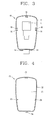
- FIG. 3 is a planar view that illustrates a structure of an exemplary body of the street lamp with plasma lighting system of the present invention.
- FIG. 4 is a rear view that illustrates a structure of an exemplary cover of the street lamp with plasma lighting system of the present invention.
- FIG. 5 is a side view that illustrates an exemplary structure of the street lamp with plasma lighting system according to a second embodiment of the present invention.
- FIG. 6 is a side view that illustrates an exemplary structure of the street lamp with plasma lighting system according to a third embodiment of the present invention.
- FIG. 1 is a side view that illustrates an open state of an exemplary cover of a street lamp with plasma lighting system according to a first embodiment of the present invention
- FIG. 2 is a side view that illustrates a closed state of the exemplary cover of the street lamp with plasma lighting system according to the first embodiment of the present invention
- FIG. 3 is a planar view that illustrates an exemplary structure of a body of the street lamp with plasma lighting system of the present invention
- FIG. 4 is a rear view that illustrates an exemplary structure of a cover of the street lamp with plasma lighting system of the present invention
- FIG. 5 is a side view that illustrates an exemplary structure of the street lamp with plasma lighting system according to a second embodiment of the present invention
- FIG. 6 is a side view that illustrates an exemplary structure of the street lamp with plasma lighting system according to a third embodiment of the present invention.
- the street lamp with plasma lighting system comprises a body 10 having an induction lamp (L) installed therein, a cover 20 that is installed to be removable from the body 10 while accommodating the induction lamp (L) within the body 10 and providing shielding thereof, and an open/close unit capable of opening and closing the cover 20 along the lengthwise direction of the body 10.
- a body 10 comprises a panel type lower surface section 11 having a certain area capable of accommodating the induction lamp (L), a first side section 12 formed to protrude at a certain height in the thickness direction of the lower surface section 11 at the edge section thereof, a body side hook projection 13 formed at one end of the lower surface section 11 and that is engaged and combined with a cover side hook projection 23 of the cover 23, and a locking projection 14 that is securely fixed and engaged with the other end of the lower surface section 11 upon being clipped by a clip 24 of the cover 20.
- L induction lamp
- first side section 12 formed to protrude at a certain height in the thickness direction of the lower surface section 11 at the edge section thereof
- a body side hook projection 13 formed at one end of the lower surface section 11 and that is engaged and combined with a cover side hook projection 23 of the cover 23, and a locking projection 14 that is securely fixed and engaged with the other end of the lower surface section 11 upon being clipped by a clip 24 of the cover 20.
- each opposing side of the body 10 has a hinge projection 15 that is formed to protrude at a certain length in the direction of the panel surface of the lower surface section 11, to act as a center of rotation for a link member 30 that receives the hinge projection 15 in a hinge hole (not marked) thereof.
- Each opposing side of the body 10 also has a link catching end 16 formed as a depressed portion (e.g., an engraved fan-shape) at one side of the first side section 12 with the hinge projection 15 at its center.
- the cover 20 comprises an upper surface section 21 corresponding to the lower surface section 11, a second side surface section 22 contacting with the first side surface section 12 by being formed at a certain height in the direction of the thickness of the upper surface section 21 at the edge section thereof, a cover side hook projection 23 that engages with the body side hook projection 13 by being formed to protrude from one end of the second side surface section 22, and a clip 24 that is formed at the other end of the second side surface section 22 to be fixed and engaged with the locking projection 14 of the body 10.
- a hinge projection 25 formed at both sides of the inner surface of the cover 20, constitutes a center of rotation upon insertion into the hinge hole (not marked) of the other end of a link member 30 (to be described hereafter) when the cover 20 is opened.
- the link member 30 may be a single link member with hinge holes at both ends, or may be multiple link members 30 that may be folded at their center portions, as illustrated in the second embodiment of FIG. 5 of the present invention.
- the single link 30 should preferably be formed to have a length that allows complete exposure of the induction lamp (L) during the open state of the cover. Further, the single link 30 may forms a sliding groove at the end so that the hinge projection 25 of the cover section can be opened and closed by sliding to the length's direction of the single link 30.
- the induction lamp (plasma lighting system) street light of the above-described structure may operate in the following manner.
- both ends of the single link 30 rotate in the counterclockwise direction about the hinge projection 15c, 25c of the body 10 with the cover 20 at the center, and the cover 20 may be placed on the upper surface 13 of the body 10.
- the locking projection 14 of the body 10 can be clipped and fixed by the clip 24 of the cover 20.
- both ends of the single link 30 also rotate in the clockwise direction about the body 10 and the hinge projection 15, 25 of the cover 20 at the center, and the cover 20 can be move away from the upper surface of the body 10.
- the link catching end 16 being formed at both side surfaces of the body 10
- the single link 30 gets caught by the link catching end 16 to restrict its rotation and thus can support the opened state of the cover 20.
- Fig. 6 is an exemplary structure of the street lamp with plasma lighting system according to the third embodiment of the present invention. Certain parts being similar to those in the related art construction are labeled with same reference numerals, and thus a detailed description with respect to these will be omitted to prevent the present features from being obscured.
- the induction lamp (L) street light may comprise: a body 10 with an induction lamp installed therein; a cover 20 that is installed to be removable from the body 10 while accommodating the induction lamp (L) within the body 10 and providing shielding thereof, a slide groove 17 formed at one surface among the contacting surfaces of the body 10 and the cover 20; and a slide projection 26 engaged to the slide groove 17 to be capable of sliding thereof.
- the cover 20 When the cover 20 is to be locked, it may be pushed up according to the lengthwise direction of the body 10, the slide projection 26 is securely received and moves to the upper side along the slide groove17. As the slide motion is proceeds, the closed state of the cover 20 is maintained since the hook projection 27 contacts with, inserts into and engages with the inserting hole 18.
- the cover 20 When the cover 20 is to be opened, it may be pushed down according to the lengthwise direction of the body 10, the hook projection 27 escapes from the inserting hole 18, and as the slide projection 26 that is securely received and moves to the lower side according to the slide groove17, the opened state of the cover 20 is maintained by being in contact with one end of the slide groove 17.
- the time it takes to open and close the cover of the induction type street light may be reduced when compared to the related art structure.
- repair and maintenance workers may be better protected from the dangers of accidents because the overall time required to perform repairs and maintenance can be reduced.
Landscapes
- Engineering & Computer Science (AREA)
- General Engineering & Computer Science (AREA)
- Non-Portable Lighting Devices Or Systems Thereof (AREA)
- Securing Globes, Refractors, Reflectors Or The Like (AREA)
Applications Claiming Priority (1)
| Application Number | Priority Date | Filing Date | Title |
|---|---|---|---|
| KR1020050020279A KR100690681B1 (ko) | 2005-03-10 | 2005-03-10 | 무전극 램프를 구비한 가로등 |
Publications (2)
| Publication Number | Publication Date |
|---|---|
| EP1701089A2 true EP1701089A2 (de) | 2006-09-13 |
| EP1701089A3 EP1701089A3 (de) | 2010-03-31 |
Family
ID=36097287
Family Applications (1)
| Application Number | Title | Priority Date | Filing Date |
|---|---|---|---|
| EP06002287A Withdrawn EP1701089A3 (de) | 2005-03-10 | 2006-02-03 | Verriegelungssystem für Strassenleuchte mit einer Plasmaentladungslampe |
Country Status (5)
| Country | Link |
|---|---|
| US (1) | US7364328B2 (de) |
| EP (1) | EP1701089A3 (de) |
| JP (1) | JP2006253121A (de) |
| KR (1) | KR100690681B1 (de) |
| CN (1) | CN101033832B (de) |
Cited By (1)
| Publication number | Priority date | Publication date | Assignee | Title |
|---|---|---|---|---|
| RU2467246C1 (ru) * | 2011-04-28 | 2012-11-20 | Общество с ограниченной ответственностью "Производственно-Коммерческая Фирма "Транском" | Светильник |
Families Citing this family (6)
| Publication number | Priority date | Publication date | Assignee | Title |
|---|---|---|---|---|
| KR100901668B1 (ko) * | 2009-02-03 | 2009-06-08 | 김종률 | 버튼식 이중잠금장치가 구비된 등기구 헤드 |
| US8256938B2 (en) * | 2009-06-15 | 2012-09-04 | Topanga Technologies, Inc. | Method and system for converting a sodium street lamp to an efficient white light source |
| CN102563549B (zh) * | 2010-12-27 | 2013-03-27 | 海洋王照明科技股份有限公司 | 一种用于灯具的快速开盖结构以及具有该结构的灯具 |
| EP2801243B8 (de) | 2012-01-05 | 2019-11-13 | Phoenix Products, LLC | Systeme und verfahren zur bereitstellung einer beleuchtung für hohe masten |
| US9801261B2 (en) * | 2012-01-05 | 2017-10-24 | Bright Light Systems, Inc. | Systems and methods for providing high-mast lighting |
| WO2019120229A1 (zh) * | 2017-12-19 | 2019-06-27 | 欧普照明股份有限公司 | 一种路灯装置 |
Family Cites Families (13)
| Publication number | Priority date | Publication date | Assignee | Title |
|---|---|---|---|---|
| GB684186A (en) * | 1950-08-30 | 1952-12-10 | Edison Swan Electric Co Ltd | Improvements in and relating to lanterns for street lighting |
| GB843025A (en) * | 1957-10-03 | 1960-08-04 | Revo Electric Co Ltd | Street lighting fittings |
| DE1793392U (de) * | 1959-04-14 | 1959-08-13 | Signalbau Huber Muenchen K G | Strassenleuchte. |
| US3755665A (en) * | 1972-09-25 | 1973-08-28 | Gen Electric | Floodlight |
| US3983387A (en) * | 1975-06-10 | 1976-09-28 | Westinghouse Electric Corporation | Concealed, spring-loaded, slide hinge for luminaire door |
| US4434456A (en) * | 1982-12-03 | 1984-02-28 | General Electric Company | Luminaire birdshield |
| US4689729A (en) * | 1986-04-21 | 1987-08-25 | Ruud Lighting | Floodlight |
| DE3937512A1 (de) * | 1989-11-10 | 1991-05-16 | Vulkan Werk Gmbh | Deckelverschluss fuer leuchten |
| US5803590A (en) * | 1996-03-08 | 1998-09-08 | Thomas & Betts Corporation | Roadway luminaire |
| JPH103814A (ja) * | 1996-06-12 | 1998-01-06 | Toshiba Lighting & Technol Corp | 照明器具および照明装置 |
| CN2506861Y (zh) * | 2001-10-25 | 2002-08-21 | 姜玉华 | 方便更换灯泡的高空路灯罩 |
| KR20040042955A (ko) * | 2002-11-14 | 2004-05-22 | 주식회사 태양전자 | 전주용 조명등 갓 |
| KR100539108B1 (ko) * | 2003-07-02 | 2005-12-27 | 송용선 | 가로등기구 |
-
2005
- 2005-03-10 KR KR1020050020279A patent/KR100690681B1/ko not_active Expired - Fee Related
-
2006
- 2006-01-13 US US11/331,029 patent/US7364328B2/en not_active Expired - Fee Related
- 2006-02-03 EP EP06002287A patent/EP1701089A3/de not_active Withdrawn
- 2006-02-06 JP JP2006028104A patent/JP2006253121A/ja not_active Withdrawn
- 2006-02-09 CN CN2006100064742A patent/CN101033832B/zh not_active Expired - Fee Related
Non-Patent Citations (1)
| Title |
|---|
| None |
Cited By (1)
| Publication number | Priority date | Publication date | Assignee | Title |
|---|---|---|---|---|
| RU2467246C1 (ru) * | 2011-04-28 | 2012-11-20 | Общество с ограниченной ответственностью "Производственно-Коммерческая Фирма "Транском" | Светильник |
Also Published As
| Publication number | Publication date |
|---|---|
| CN101033832B (zh) | 2010-09-08 |
| JP2006253121A (ja) | 2006-09-21 |
| CN101033832A (zh) | 2007-09-12 |
| KR20060099203A (ko) | 2006-09-19 |
| KR100690681B1 (ko) | 2007-03-09 |
| US7364328B2 (en) | 2008-04-29 |
| EP1701089A3 (de) | 2010-03-31 |
| US20060203500A1 (en) | 2006-09-14 |
Similar Documents
| Publication | Publication Date | Title |
|---|---|---|
| US20100053947A1 (en) | Lighting device and lens assembly | |
| US20070206376A1 (en) | Adjustable lighting fixture | |
| US20110317407A1 (en) | Fixture installation apparatus and method | |
| CN1880837A (zh) | 可调节照明器材 | |
| US7364328B2 (en) | Open/shut structure for street lamp with plasma lighting system | |
| US6805470B1 (en) | Light fixture including an improved latch mechanism | |
| US9970607B2 (en) | Retractable lighting assembly | |
| US3634681A (en) | Integral ballast, lampholder support and wireway | |
| CA2551740A1 (en) | Recessed lighting fixture | |
| JP2003203506A (ja) | 屋外照明器具 | |
| KR200339105Y1 (ko) | 조명기구 | |
| US2883519A (en) | Luminaire | |
| KR200329866Y1 (ko) | 비상구 유도등 | |
| CN210050637U (zh) | 具有挡光结构的投光灯具 | |
| JP2008226749A (ja) | 埋込型照明器具 | |
| JPH0686211U (ja) | 照明器具 | |
| JP4312336B2 (ja) | 道路照明器具 | |
| JP2008520073A (ja) | 照明用器具、および照明用器具のための薄板ルーバー | |
| JP2007035292A (ja) | 照明器具 | |
| KR200422504Y1 (ko) | 조명등 커버 | |
| KR0119955Y1 (ko) | 천정매입형 형광등기구 | |
| JPH10106323A (ja) | 照明器具 | |
| JP2003257209A (ja) | 照明装置 | |
| JPH0581905A (ja) | 照明器具 | |
| GB2387646A (en) | An improved luminaire |
Legal Events
| Date | Code | Title | Description |
|---|---|---|---|
| PUAI | Public reference made under article 153(3) epc to a published international application that has entered the european phase |
Free format text: ORIGINAL CODE: 0009012 |
|
| 17P | Request for examination filed |
Effective date: 20060303 |
|
| AK | Designated contracting states |
Kind code of ref document: A2 Designated state(s): AT BE BG CH CY CZ DE DK EE ES FI FR GB GR HU IE IS IT LI LT LU LV MC NL PL PT RO SE SI SK TR |
|
| AX | Request for extension of the european patent |
Extension state: AL BA HR MK YU |
|
| PUAL | Search report despatched |
Free format text: ORIGINAL CODE: 0009013 |
|
| AK | Designated contracting states |
Kind code of ref document: A3 Designated state(s): AT BE BG CH CY CZ DE DK EE ES FI FR GB GR HU IE IS IT LI LT LU LV MC NL PL PT RO SE SI SK TR |
|
| AX | Request for extension of the european patent |
Extension state: AL BA HR MK YU |
|
| AKX | Designation fees paid |
Designated state(s): DE FR GB IT |
|
| STAA | Information on the status of an ep patent application or granted ep patent |
Free format text: STATUS: THE APPLICATION IS DEEMED TO BE WITHDRAWN |
|
| 18D | Application deemed to be withdrawn |
Effective date: 20101001 |