EP1702168B1 - Getriebe mit ersten, zweiten und dritten parallelen wellen und von diesen wellen getragenen zahnrädern - Google Patents
Getriebe mit ersten, zweiten und dritten parallelen wellen und von diesen wellen getragenen zahnrädern Download PDFInfo
- Publication number
- EP1702168B1 EP1702168B1 EP04800378A EP04800378A EP1702168B1 EP 1702168 B1 EP1702168 B1 EP 1702168B1 EP 04800378 A EP04800378 A EP 04800378A EP 04800378 A EP04800378 A EP 04800378A EP 1702168 B1 EP1702168 B1 EP 1702168B1
- Authority
- EP
- European Patent Office
- Prior art keywords
- shaft
- gearwheels
- gearwheel
- transmission
- disengaged
- Prior art date
- Legal status (The legal status is an assumption and is not a legal conclusion. Google has not performed a legal analysis and makes no representation as to the accuracy of the status listed.)
- Expired - Lifetime
Links
- 230000005540 biological transmission Effects 0.000 title claims abstract description 35
- 230000007935 neutral effect Effects 0.000 claims description 20
- 239000000470 constituent Substances 0.000 description 2
- 238000002485 combustion reaction Methods 0.000 description 1
- 238000000034 method Methods 0.000 description 1
Images



Classifications
-
- F—MECHANICAL ENGINEERING; LIGHTING; HEATING; WEAPONS; BLASTING
- F16—ENGINEERING ELEMENTS AND UNITS; GENERAL MEASURES FOR PRODUCING AND MAINTAINING EFFECTIVE FUNCTIONING OF MACHINES OR INSTALLATIONS; THERMAL INSULATION IN GENERAL
- F16H—GEARING
- F16H3/00—Toothed gearings for conveying rotary motion with variable gear ratio or for reversing rotary motion
- F16H3/02—Toothed gearings for conveying rotary motion with variable gear ratio or for reversing rotary motion without gears having orbital motion
- F16H3/08—Toothed gearings for conveying rotary motion with variable gear ratio or for reversing rotary motion without gears having orbital motion exclusively or essentially with continuously meshing gears, that can be disengaged from their shafts
- F16H3/087—Toothed gearings for conveying rotary motion with variable gear ratio or for reversing rotary motion without gears having orbital motion exclusively or essentially with continuously meshing gears, that can be disengaged from their shafts characterised by the disposition of the gears
- F16H3/093—Toothed gearings for conveying rotary motion with variable gear ratio or for reversing rotary motion without gears having orbital motion exclusively or essentially with continuously meshing gears, that can be disengaged from their shafts characterised by the disposition of the gears with two or more countershafts
-
- F—MECHANICAL ENGINEERING; LIGHTING; HEATING; WEAPONS; BLASTING
- F16—ENGINEERING ELEMENTS AND UNITS; GENERAL MEASURES FOR PRODUCING AND MAINTAINING EFFECTIVE FUNCTIONING OF MACHINES OR INSTALLATIONS; THERMAL INSULATION IN GENERAL
- F16H—GEARING
- F16H3/00—Toothed gearings for conveying rotary motion with variable gear ratio or for reversing rotary motion
- F16H3/02—Toothed gearings for conveying rotary motion with variable gear ratio or for reversing rotary motion without gears having orbital motion
- F16H3/08—Toothed gearings for conveying rotary motion with variable gear ratio or for reversing rotary motion without gears having orbital motion exclusively or essentially with continuously meshing gears, that can be disengaged from their shafts
- F16H3/087—Toothed gearings for conveying rotary motion with variable gear ratio or for reversing rotary motion without gears having orbital motion exclusively or essentially with continuously meshing gears, that can be disengaged from their shafts characterised by the disposition of the gears
- F16H3/093—Toothed gearings for conveying rotary motion with variable gear ratio or for reversing rotary motion without gears having orbital motion exclusively or essentially with continuously meshing gears, that can be disengaged from their shafts characterised by the disposition of the gears with two or more countershafts
- F16H2003/0931—Toothed gearings for conveying rotary motion with variable gear ratio or for reversing rotary motion without gears having orbital motion exclusively or essentially with continuously meshing gears, that can be disengaged from their shafts characterised by the disposition of the gears with two or more countershafts each countershaft having an output gear meshing with a single common gear on the output shaft
-
- F—MECHANICAL ENGINEERING; LIGHTING; HEATING; WEAPONS; BLASTING
- F16—ENGINEERING ELEMENTS AND UNITS; GENERAL MEASURES FOR PRODUCING AND MAINTAINING EFFECTIVE FUNCTIONING OF MACHINES OR INSTALLATIONS; THERMAL INSULATION IN GENERAL
- F16H—GEARING
- F16H2200/00—Transmissions for multiple ratios
- F16H2200/003—Transmissions for multiple ratios characterised by the number of forward speeds
- F16H2200/0065—Transmissions for multiple ratios characterised by the number of forward speeds the gear ratios comprising nine forward speeds
-
- Y—GENERAL TAGGING OF NEW TECHNOLOGICAL DEVELOPMENTS; GENERAL TAGGING OF CROSS-SECTIONAL TECHNOLOGIES SPANNING OVER SEVERAL SECTIONS OF THE IPC; TECHNICAL SUBJECTS COVERED BY FORMER USPC CROSS-REFERENCE ART COLLECTIONS [XRACs] AND DIGESTS
- Y10—TECHNICAL SUBJECTS COVERED BY FORMER USPC
- Y10T—TECHNICAL SUBJECTS COVERED BY FORMER US CLASSIFICATION
- Y10T74/00—Machine element or mechanism
- Y10T74/19—Gearing
- Y10T74/19219—Interchangeably locked
- Y10T74/19223—Disconnectable counter shaft
-
- Y—GENERAL TAGGING OF NEW TECHNOLOGICAL DEVELOPMENTS; GENERAL TAGGING OF CROSS-SECTIONAL TECHNOLOGIES SPANNING OVER SEVERAL SECTIONS OF THE IPC; TECHNICAL SUBJECTS COVERED BY FORMER USPC CROSS-REFERENCE ART COLLECTIONS [XRACs] AND DIGESTS
- Y10—TECHNICAL SUBJECTS COVERED BY FORMER USPC
- Y10T—TECHNICAL SUBJECTS COVERED BY FORMER US CLASSIFICATION
- Y10T74/00—Machine element or mechanism
- Y10T74/19—Gearing
- Y10T74/19219—Interchangeably locked
- Y10T74/19233—Plurality of counter shafts
Definitions
- the present invention relates to a transmission, comprising first, second and third parallel shafts, rotatably supported in a casing, and gearwheels which are carried by the shafts and which intermesh with one another in pairs for transmitting torque either between the first shaft and the third shaft, or between the second shaft and the third shaft, and of which at least one gearwheel in each pair of intermeshing gearwheels is rotatably supported on its shaft and can be locked to or disengaged from its shaft by means of associated clutch members.
- a generic transmission is known from US 5 592 854 .
- next gear is usually pre-selected by engagement of the relevant gearwheel on the currently non-driven intermediate shaft prior to the actual gearshift, so that the actual gearshift can, in principle, take place without interruption of the torque through simultaneous disengagement of the currently engaged disk clutch and engagement of the other disk clutch.
- Such "power shift" gearboxes are often used in heavier trucks and plant vehicles and commonly have a total of ten or more gear ratios.
- a known method of minimizing the number of input shafts with associated clutch members is to have some or all gearwheels on the output shaft mesh with corresponding gearwheels on the two intermediate shafts. This means that the freedom to select steps between the various gears is more limited the greater the number of gearwheels on the intermediate shafts that mesh with common gearwheels on the output shaft. Maximum freedom, on the other hand, is obtained if each intermediate shaft gearwheel meshes with its own gearwheel on the output shaft, but this is then achieved at the expense of an increased number of requisite components.
- the object of the invention is generally to provide a transmission of the type specified in the introductory part, which having few constituent components permits a large number of gear ratios with even steps between the gears.
- this object is achieved in that at least two gearwheels rotatably supported on the first shaft and two gearwheels rotatably supported on the second shaft are coordinated by clutch members, which have neutral positions, in which both gearwheels are disengaged from their shaft and from one another, first engagement positions, in which the gearwheels are disengaged from the shaft but are coupled together for rotation together, and second engagement positions, in which one of the gearwheels is disengaged and one is locked to the shaft, and that said two gearwheels mesh with gearwheels on the third shaft in order to permit the transmission of torque from the first shaft via the third and the second shaft to the third, or from the second shaft via the third and the first shaft to the third shaft.
- three gearwheels are used on the first and the second shaft, the gearwheels being coordinated by clutch members, which have first engagement positions, in which either the first and the second or the second and the third gearwheel are disengaged from the associated shaft but are coupled together for rotation together.
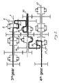
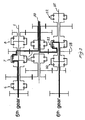
- FIG. 1 to 5 show schematic longitudinal sections through an embodiment of a transmission according to the present invention with the torque transmission in the various gears marked.
- the transmission has a first shaft 1, which is rotatably supported in a casing (not shown) and has a gearwheel 2 fixedly connected to the shaft, and three gearwheels 3, 4 and 5 which are rotatably supported on the shaft and which are coordinated by three clutch devices 6, 7 and 8, which each comprise a hub 9, 10 and 11 fixedly connected to the shaft 1, a clutch sleeve 12, 13 and 14, supported so that it is axially displaceable on the respective hub 9-11, and synchromesh devices not shown in more detail.
- the transmission furthermore has a second shaft 15, which is rotatably supported in the casing and has a gearwheel 16 fixedly connected to the shaft, and three gearwheels 17, 18 and 19 which are rotatably supported on the shaft and which are coordinated by three clutch devices 20, 21 and 22, which each comprise a hub 23, 24 and 25 fixedly connected to the shaft, a clutch sleeve 26, 27 and 28, supported so that it is axially displaceable on the respective hub 23-25, and synchromesh devices not shown in more detail.
- a third shaft 30 rotatably supported in the casing has two gearwheels 31 and 32 fixedly connected to the shaft, a first pair of gearwheels 33 and 34 which are connected to one another and are capable of rotating together on the shaft, and a second pair of gearwheels 35 and 36, which are connected to one another and are capable of rotating together on the shaft.
- the pairs of gearwheels 33, 34 and 35, 36 are each coordinated by their clutch device 37 and 38 respectively, which each comprise a hub 39 and 40 fixedly connected to the shaft 30, a clutch sleeve 41 and 42 respectively, supported so that it is axially displaceable on the respective hub 39, 40, and synchromesh devices not shown in more detail.
- the clutch device 6 on the shaft 1 has two positions, that is a neutral position, in which it disengages the gearwheel 3 from the shaft 1, and an engagement position, in which it locks the gearwheel 3 to the shaft 1.
- the clutch 7 on the shaft 1 has three positions, that is a neutral position, in which it disengages the gearwheels 3 and 4 from the shaft 1 and from one another, a first engagement position, in which it disengages the gearwheels 3 and 4 from the shaft 1 but keeps them coupled together, and a second engagement position, in which it disengages the gearwheel 3 from the shaft 1 and locks the gearwheel 4 to the shaft 1.
- the clutch 8 on the shaft 1 has three positions, that is a neutral position, in which it disengages the gearwheels 4 and 5 from the shaft 1 and from one another, a first engagement position, in which it disengages the gearwheels 4 and 5 from the shaft but keeps them coupled together, and a second engagement position, in which it disengages the gearwheel 4 from the shaft 1 and locks the gearwheel 5 to the shaft 1.
- the clutch 20 on the shaft 2 has three positions, that is a neutral position, in which it disengages the gearwheels 17 and 18 from the shaft 2 and from one another, a first engagement position, in which it disengages the gearwheels 17 and 18 from the shaft 2 but keeps them coupled together, and a second engagement position, in which it disengages the gearwheel 18 from the shaft and locks the gearwheel 17 to the shaft 2.
- the clutch 21 on the shaft 2 has three positions, that is a neutral position, in which it disengages the gearwheels 18 and 19 from the shaft 2 and from one another, a first engagement position, in which it disengages the gearwheels 18 and 19 from the shaft but keeps them coupled together, and a second engagement position, in which it disengages the gearwheel 19 from the shaft and locks the gearwheel 18 to the shaft 2.
- the clutch 22 on the shaft 2 has two positions, that is a neutral position, in which it disengages the gearwheel 19 from the shaft 2, and an engagement position, which locks the gearwheel 19 to the shaft 2.
- the clutches 37 and 38 on the shaft 30 have two positions, that is a neutral position, in which the gearwheel pairs 33 and 34, 35 and 36 are disengaged from the shaft 30, and an engagement position, in which the gearwheel pairs 33 and 34, 35 and 36 are locked to the shaft 30.
- the gearwheels 2 and 16 on the shafts 1 and 15 respectively are designed to be driven alternately by a pair of input shafts, each via its disk clutch (not shown).
- the shafts 1 and 15 then form a pair of intermediate shafts and the shaft 30 and output shaft.
- power shift type torque is transmitted via the one intermediate shaft in all odd gears and via the other intermediate shaft in all even gears.
- Figs. 1 to 5 illustrate the torque transmission path of the various transmission steps in a transmission having ten gears.
- Fig. 1 illustrates the torque transmission in 1 st and 2 nd gear.
- the clutch 6 is in its neutral position
- the clutch 7 is in its first engagement position
- the clutch 8 is in its second engagement position.
- the clutches 37 and 38 on the shaft 30 are in their neutral positions, whilst the clutch 20 on the shaft 15 is in its second engagement position and locks the gearwheel 17 to the shaft.
- the clutch 21 is in its first engagement position and the clutch 22 in its neutral position.
- Fig. 2 illustrates the torque transmission in 3 rd and 4 th gear.
- the clutch 8 when transmitting torque in 3 rd gear the clutch 8 is in its second engagement position and locks the gearwheel 5 to the shaft 1, but instead of serving only as intermediate gear, the gearwheel 35 is now locked to the shaft 30 by the clutch 38 for transmitting torque directly from the shaft 1 to the shaft 30 via the gearwheels 5 and 35.
- the clutch 20 when transmitting torque in 4 th gear the clutch 20 is in its second engagement position and locks the gearwheel 17 to the shaft 15 for transmitting torque directly from the shaft 15 to the shaft 30 via the gearwheels 17 and 34, which are locked to the shaft 30 by the clutch 37.
- Fig. 3 illustrates the torque transmission in 5 th and 6 th gear.
- the shaft 1 drives, the clutches 6 and 8 are in their neutral positions and the clutch 7 is in its second engagement position and locks the gearwheel 4 to the shaft 1.
- the gearwheel 31 fixed to the shaft 30 torque is transmitted directly to the shaft 30.
- the clutches 20 and 22 are in their neutral positions and the clutch 21 is in its second engagement position and locks the gearwheel 18 to the shaft 15.
- torque is transmitted directly to the shaft 30.
- Fig. 4 illustrates the torque transmission in 7 th and 8 th gear.
- the shaft 1 drives, the clutches 7 and 8 are in their neutral positions and the clutch 6 is in its engagement position and locks the gearwheel 3 to the shaft 1.
- the clutch 37 is in its engagement position and locks the gearwheel pair 33, 34 to the shaft 30 for transmitting torque from the shaft 1 to the shaft 30 via the gearwheel 3 and the gearwheel pair 33, 34.
- the shaft 15 drives, the clutches 20 and 21 are in their neutral positions and the clutch 22 is in its engagement position and locks the gearwheel 19 to the shaft 16.
- the clutch 38 is in its engagement position for locking the gearwheel pair 35, 36 to the shaft 30 and transmitting torque from the shaft 15 to the shaft 30.
- Fig. 5 illustrates the torque transmission in 9 th and 10 th gear.
- the shaft 1 drives.
- the clutch 7 is in its neutral position, whilst the clutch 6 is in its engagement position and locks the gearwheel 3 to the shaft 1.
- 10 th gear is pre-selected in that the clutch 8 is in its first engagement position.
- the clutches 37 and 38 are in their neutral positions, whilst the clutch 20 on the shaft 15 is in its first engagement position and locks the gearwheels 17 and 18 together at the same time that these are disengaged from the shaft 15.
- the torque is now transmitted from the gearwheel 3 on the shaft 1 via the disengaged gearwheel pair 33, 34 on the shaft 30 and the disengaged gearwheel pair 17, 18 on the shaft 16 to the fixed gearwheel 31 on the shaft 30.
- the gearwheels 17 and 17 are disengaged from the shaft 15 by the clutches 20 and 21, whilst the clutch 22 is in its engagement position and locks the gearwheel 19 to the shaft 15.
- the clutches 37 and 38 are in their neutral positions, whilst the clutch 8 on the shaft 1 is in its first engagement position and locks the gearwheels 4, 5 together at the same time that these are disengaged from the shaft 1.
- the torque is now transmitted from the gearwheel 19 on the shaft 15 via the disengaged gearwheel pair 35, 36 on the shaft 30 and the disengaged gearwheel pair 4, 5 on the shaft 1 to the fixed gearwheel 31 on the shaft 30.
- clutches 7, 8, 20 and 21 are therefore used, which in addition to the usual functions for transmission clutches of locking and disengaging gearwheels on an associated shaft here also have the further function of being able to lock adjacent gearwheels to the shaft together without locking the gearwheels on the shaft.
- Coupled gearwheels of different diameters can thereby be used to transmit torque with a gear ratio step from a driving shaft via an output shaft to a third shaft and thence back to the output shaft.
- a ten-gear transmission is achieved using just eleven gearwheels, except for the primary drive gearwheels.
Landscapes
- Engineering & Computer Science (AREA)
- General Engineering & Computer Science (AREA)
- Mechanical Engineering (AREA)
- Structure Of Transmissions (AREA)
- Gear Transmission (AREA)
- Shafts, Cranks, Connecting Bars, And Related Bearings (AREA)
- Motorcycle And Bicycle Frame (AREA)
- Chair Legs, Seat Parts, And Backrests (AREA)
- Devices For Conveying Motion By Means Of Endless Flexible Members (AREA)
- Magnetic Resonance Imaging Apparatus (AREA)
- Toys (AREA)
- Connection Of Motors, Electrical Generators, Mechanical Devices, And The Like (AREA)
Claims (4)
- Getriebe mit ersten, zweiten und dritten parallelen Wellen, die drehbar in einem Gehäuse gelagert sind, und mit Zahnrädern, die von den Wellen getragen werden und die miteinander paarweise für eine Übertragung eines Drehmoments entweder zwischen der ersten Welle und der dritten Welle oder zwischen der zweiten Welle und der dritten Welle in Eingriff stehen und von denen wenigstens ein Zahnrad in jedem Paar in Eingriff stehender Zahnräder drehbar auf seiner Welle gelagert ist und mittels zugeordneter Kupplungselemente auf seiner Welle festgestellt oder von seiner Welle gelöst werden kann, dadurch gekennzeichnet, dass wenigstens zwei drehbar auf der ersten Welle (1) gelagerte Zahnräder (3, 4, 5) und zwei drehbar auf der zweiten Welle (15) gelagerte Zahnräder (17, 18, 19) durch Kupplungselemente (6, 7, 8 bzw. 23, 24, 25) koordiniert werden, die neutrale Positionen aufweisen, in denen die Zahnräder von ihrer Welle und voneinander gelöst sind, erste Eingriffspositionen aufweisen, in denen die Zahnräder von der Welle gelöst jedoch miteinander für eine Drehung miteinander gekoppelt sind, und zweite Eingriffspositionen aufweisen, in denen eines der Zahnräder gelöst und eines auf der Welle festgestellt ist, und dass die Zahnräder auf jeder Welle mit Zahnrädern (33, 34, 31, 35, 36) auf der dritten Welle (30) in Eingriff stehen, um die Übertragung eines Drehmoments von der ersten Welle über die dritte und die zweite Welle zurück auf die dritte Welle und von der zweiten Welle über die dritte und die erste Welle zurück zu der dritten Welle zu ermöglichen.
- Getriebe nach Anspruch 1, dadurch gekennzeichnet, dass ein erstes, ein zweites und ein drittes Zahnrad (3, 4, 5 und 17, 18, 19) drehbar auf der ersten Welle und auf der zweiten Welle (1 bzw. 15) gelagert sind, wobei die Zahnräder durch Kupplungselemente (6, 7, 8) koordiniert werden, die neutrale Positionen, in denen die Zahnräder von ihrer Welle gelöst sind, erste Eingriffspositionen, in denen entweder das erste und das zweite Zahnrad (3, 4 und 17, 18) oder das zweite und das dritte Zahnrad (4. 5 und 18, 19) von der zugeordneten Welle gelöst sind, jedoch miteinander für eine Drehung miteinander gekoppelt sind, und zweite Eingriffspositionen aufweisen, in denen eines der Zahnräder auf der Welle festgestellt ist und die anderen gelöst sind.
- Getriebe nach Anspruch 2, dadurch gekennzeichnet, dass ein Zahnrad (4, 18) der drei Zahnräder, die drehbar auf der ersten bzw. zweiten Welle (1, 15) gelagert sind und die auf der jeweiligen Welle mittels Kupplungselementen (7, 21) festgestellt werden können, mit einem gemeinsamen Zahnrad (31) kämmen, das auf der dritten Welle (30) angeordnet ist, während die anderen zwei Zahnräder (3, 5 und 19, 19) auf der ersten und der zweiten Welle jeweils mit individuellen Zahnrädern (33, 34 und 35, 36) auf der dritten Welle kämmen.
- Getriebe nach Anspruch 3, dadurch gekennzeichnet, dass die dritte Welle vier Zahnräder (33, 34, 35, 36) aufweist, die paarweise drehen können und die mittels Kupplungselementen auf der Welle festgestellt werden können, wobei ein Zahnrad (33, 35) der Zahnräder, die paarweise drehen können, mit einem Zahnrad (3, 5) auf der ersten Welle (1) kämmt, während das zweite Zahnrad (34, 36) der Zahnräder, die paarweise drehen können, mit einem Zahnrad (17, 19) auf der zweiten Welle (15) kämmt.
Applications Claiming Priority (2)
| Application Number | Priority Date | Filing Date | Title |
|---|---|---|---|
| SE0303530A SE526221C2 (sv) | 2003-12-22 | 2003-12-22 | Transmission innefattande första, andra och tredje parallella axlar och av axlarna uppburna kugghjul |
| PCT/SE2004/001717 WO2005061923A1 (en) | 2003-12-22 | 2004-11-24 | Transmission |
Publications (2)
| Publication Number | Publication Date |
|---|---|
| EP1702168A1 EP1702168A1 (de) | 2006-09-20 |
| EP1702168B1 true EP1702168B1 (de) | 2007-08-08 |
Family
ID=30768845
Family Applications (1)
| Application Number | Title | Priority Date | Filing Date |
|---|---|---|---|
| EP04800378A Expired - Lifetime EP1702168B1 (de) | 2003-12-22 | 2004-11-24 | Getriebe mit ersten, zweiten und dritten parallelen wellen und von diesen wellen getragenen zahnrädern |
Country Status (6)
| Country | Link |
|---|---|
| US (1) | US7261011B2 (de) |
| EP (1) | EP1702168B1 (de) |
| AT (1) | ATE369509T1 (de) |
| DE (1) | DE602004008114T2 (de) |
| SE (1) | SE526221C2 (de) |
| WO (1) | WO2005061923A1 (de) |
Families Citing this family (1)
| Publication number | Priority date | Publication date | Assignee | Title |
|---|---|---|---|---|
| US7555824B2 (en) * | 2006-08-09 | 2009-07-07 | Hrl Laboratories, Llc | Method for large scale integration of quartz-based devices |
Family Cites Families (8)
| Publication number | Priority date | Publication date | Assignee | Title |
|---|---|---|---|---|
| SE470467B (sv) * | 1992-09-21 | 1994-05-02 | Volvo Ab | Motorfordonsväxellåda |
| JP2000512365A (ja) * | 1996-03-08 | 2000-09-19 | ボルボ ラストバグナー アーベー | 自動車歯車箱 |
| SE506214C2 (sv) * | 1996-03-15 | 1997-11-24 | Volvo Ab | Motorfordonsväxellåda |
| US6186029B1 (en) * | 1997-07-09 | 2001-02-13 | Dana Corporation | Dual input transmission |
| JP3691979B2 (ja) * | 1999-02-03 | 2005-09-07 | 本田技研工業株式会社 | 平行軸式変速機 |
| FR2790297B1 (fr) * | 1999-02-26 | 2001-04-13 | Renault | Synchronisation multiple d'une boite de vitesses a commande dite robotisee |
| DE10060699A1 (de) * | 1999-12-16 | 2001-06-21 | Luk Lamellen & Kupplungsbau | Getriebe und Verfahren zum Betreiben eines Getriebes |
| US7080566B2 (en) * | 2004-03-18 | 2006-07-25 | Ford Global Technologies, Llc | Ranged single clutch layshaft powershift automatic transmission |
-
2003
- 2003-12-22 SE SE0303530A patent/SE526221C2/sv not_active IP Right Cessation
-
2004
- 2004-11-24 DE DE602004008114T patent/DE602004008114T2/de not_active Expired - Lifetime
- 2004-11-24 AT AT04800378T patent/ATE369509T1/de not_active IP Right Cessation
- 2004-11-24 WO PCT/SE2004/001717 patent/WO2005061923A1/en not_active Ceased
- 2004-11-24 EP EP04800378A patent/EP1702168B1/de not_active Expired - Lifetime
-
2006
- 2006-06-01 US US11/421,685 patent/US7261011B2/en not_active Expired - Fee Related
Also Published As
| Publication number | Publication date |
|---|---|
| SE526221C2 (sv) | 2005-08-02 |
| EP1702168A1 (de) | 2006-09-20 |
| DE602004008114D1 (de) | 2007-09-20 |
| WO2005061923A1 (en) | 2005-07-07 |
| DE602004008114T2 (de) | 2008-04-24 |
| US20060213299A1 (en) | 2006-09-28 |
| US7261011B2 (en) | 2007-08-28 |
| ATE369509T1 (de) | 2007-08-15 |
| SE0303530D0 (sv) | 2003-12-22 |
| SE0303530L (sv) | 2005-06-23 |
Similar Documents
| Publication | Publication Date | Title |
|---|---|---|
| US6244123B1 (en) | Multiple-speed gearbox of 3-shaft design, especially for motor vehicles | |
| US8365623B2 (en) | Double clutch transmission | |
| US9115789B2 (en) | Double clutch transmission | |
| US5125282A (en) | Motor vehicle two countershaft transmission change-speed gearbox and method | |
| US8342048B2 (en) | Dual clutch transmission | |
| US8166842B2 (en) | Dual clutch transmission | |
| US6743139B1 (en) | Multi-speed dual-clutch planetary transmissions having output shaft interconnected with three gear members | |
| US6743142B1 (en) | Multi-speed dual-clutch planetary transmission mechanisms having three interconnecting members | |
| EP2167843B1 (de) | Doppelkupplungsgetriebe mit planetengetriebesatz | |
| US6743144B1 (en) | Multi-speed dual-clutch planetary transmissions having three continuously interconnected gear members | |
| US6764425B2 (en) | Multi-speed dual-clutch planetary transmissions having four fixed interconnecting members | |
| US6852059B2 (en) | Six-speed dual-clutch transmissions having planetary gear sets with two interconnecting members | |
| US6752736B1 (en) | Multi-speed dual-clutch planetary transmissions having a stationary fourth gear set member | |
| US5150628A (en) | Gearbox for automotive vehicles | |
| US6755765B2 (en) | Multi-speed dual-clutch planetary transmissions having three gear members continuously interconnected with output shaft | |
| US20080245166A1 (en) | Dual clutch transmission having reduced axial length | |
| EP1422445A2 (de) | Mehrgang Planetengetriebe mit Doppelkupplung, vier Umlaufrädersätzen und ein festes Reaktionsglied | |
| EP1435478A2 (de) | Mehrgangsgetriebefamilie mit Doppelkupplung mit vier Umlaufsgetriebe und mit vier Bremsen | |
| EP1422444A2 (de) | Mehrgang-Planetengetriebe mit Doppelkupplung | |
| EP1422446A2 (de) | Mehrgang Planetengetriebe mit Doppelkupplung, drei Verbundglieder und vier Bremsen | |
| CN101260919A (zh) | 具有副轴传动装置的多速变速器 | |
| US6746363B1 (en) | Multi-speed dual-clutch planetary transmission mechanisms having a stationary gear member and one brake | |
| US4627301A (en) | Change speed transmission | |
| USRE33336E (en) | Change speed transmission | |
| EP1422441A2 (de) | Familie von Mehrgang-Planetengetrieben mit Doppelkupplung und vier miteinander verbundenen Planetensätzen |
Legal Events
| Date | Code | Title | Description |
|---|---|---|---|
| PUAI | Public reference made under article 153(3) epc to a published international application that has entered the european phase |
Free format text: ORIGINAL CODE: 0009012 |
|
| 17P | Request for examination filed |
Effective date: 20060724 |
|
| AK | Designated contracting states |
Kind code of ref document: A1 Designated state(s): AT BE BG CH CY CZ DE DK EE ES FI FR GB GR HU IE IS IT LI LU MC NL PL PT RO SE SI SK TR |
|
| GRAP | Despatch of communication of intention to grant a patent |
Free format text: ORIGINAL CODE: EPIDOSNIGR1 |
|
| DAX | Request for extension of the european patent (deleted) | ||
| RTI1 | Title (correction) |
Free format text: TRANSMISSION COMPRISING FIRST, SECOND AND THIRD PARALLEL SHAFTS AND GEARWHEELS WHICH ARE CARRIED BY THE SHAFTS |
|
| GRAS | Grant fee paid |
Free format text: ORIGINAL CODE: EPIDOSNIGR3 |
|
| GRAA | (expected) grant |
Free format text: ORIGINAL CODE: 0009210 |
|
| AK | Designated contracting states |
Kind code of ref document: B1 Designated state(s): AT BE BG CH CY CZ DE DK EE ES FI FR GB GR HU IE IS IT LI LU MC NL PL PT RO SE SI SK TR |
|
| REG | Reference to a national code |
Ref country code: GB Ref legal event code: FG4D |
|
| REG | Reference to a national code |
Ref country code: CH Ref legal event code: EP |
|
| REG | Reference to a national code |
Ref country code: IE Ref legal event code: FG4D |
|
| REF | Corresponds to: |
Ref document number: 602004008114 Country of ref document: DE Date of ref document: 20070920 Kind code of ref document: P |
|
| PG25 | Lapsed in a contracting state [announced via postgrant information from national office to epo] |
Ref country code: FI Free format text: LAPSE BECAUSE OF FAILURE TO SUBMIT A TRANSLATION OF THE DESCRIPTION OR TO PAY THE FEE WITHIN THE PRESCRIBED TIME-LIMIT Effective date: 20070808 Ref country code: ES Free format text: LAPSE BECAUSE OF FAILURE TO SUBMIT A TRANSLATION OF THE DESCRIPTION OR TO PAY THE FEE WITHIN THE PRESCRIBED TIME-LIMIT Effective date: 20071119 Ref country code: BG Free format text: LAPSE BECAUSE OF FAILURE TO SUBMIT A TRANSLATION OF THE DESCRIPTION OR TO PAY THE FEE WITHIN THE PRESCRIBED TIME-LIMIT Effective date: 20071108 Ref country code: NL Free format text: LAPSE BECAUSE OF FAILURE TO SUBMIT A TRANSLATION OF THE DESCRIPTION OR TO PAY THE FEE WITHIN THE PRESCRIBED TIME-LIMIT Effective date: 20070808 Ref country code: IS Free format text: LAPSE BECAUSE OF FAILURE TO SUBMIT A TRANSLATION OF THE DESCRIPTION OR TO PAY THE FEE WITHIN THE PRESCRIBED TIME-LIMIT Effective date: 20071208 |
|
| NLV1 | Nl: lapsed or annulled due to failure to fulfill the requirements of art. 29p and 29m of the patents act | ||
| REG | Reference to a national code |
Ref country code: CH Ref legal event code: PL |
|
| PG25 | Lapsed in a contracting state [announced via postgrant information from national office to epo] |
Ref country code: AT Free format text: LAPSE BECAUSE OF FAILURE TO SUBMIT A TRANSLATION OF THE DESCRIPTION OR TO PAY THE FEE WITHIN THE PRESCRIBED TIME-LIMIT Effective date: 20070808 Ref country code: LI Free format text: LAPSE BECAUSE OF FAILURE TO SUBMIT A TRANSLATION OF THE DESCRIPTION OR TO PAY THE FEE WITHIN THE PRESCRIBED TIME-LIMIT Effective date: 20070808 Ref country code: CH Free format text: LAPSE BECAUSE OF FAILURE TO SUBMIT A TRANSLATION OF THE DESCRIPTION OR TO PAY THE FEE WITHIN THE PRESCRIBED TIME-LIMIT Effective date: 20070808 Ref country code: PL Free format text: LAPSE BECAUSE OF FAILURE TO SUBMIT A TRANSLATION OF THE DESCRIPTION OR TO PAY THE FEE WITHIN THE PRESCRIBED TIME-LIMIT Effective date: 20070808 |
|
| PG25 | Lapsed in a contracting state [announced via postgrant information from national office to epo] |
Ref country code: BE Free format text: LAPSE BECAUSE OF FAILURE TO SUBMIT A TRANSLATION OF THE DESCRIPTION OR TO PAY THE FEE WITHIN THE PRESCRIBED TIME-LIMIT Effective date: 20070808 |
|
| EN | Fr: translation not filed | ||
| PG25 | Lapsed in a contracting state [announced via postgrant information from national office to epo] |
Ref country code: DK Free format text: LAPSE BECAUSE OF FAILURE TO SUBMIT A TRANSLATION OF THE DESCRIPTION OR TO PAY THE FEE WITHIN THE PRESCRIBED TIME-LIMIT Effective date: 20070808 Ref country code: GR Free format text: LAPSE BECAUSE OF FAILURE TO SUBMIT A TRANSLATION OF THE DESCRIPTION OR TO PAY THE FEE WITHIN THE PRESCRIBED TIME-LIMIT Effective date: 20071109 |
|
| PG25 | Lapsed in a contracting state [announced via postgrant information from national office to epo] |
Ref country code: SK Free format text: LAPSE BECAUSE OF FAILURE TO SUBMIT A TRANSLATION OF THE DESCRIPTION OR TO PAY THE FEE WITHIN THE PRESCRIBED TIME-LIMIT Effective date: 20070808 Ref country code: CZ Free format text: LAPSE BECAUSE OF FAILURE TO SUBMIT A TRANSLATION OF THE DESCRIPTION OR TO PAY THE FEE WITHIN THE PRESCRIBED TIME-LIMIT Effective date: 20070808 Ref country code: PT Free format text: LAPSE BECAUSE OF FAILURE TO SUBMIT A TRANSLATION OF THE DESCRIPTION OR TO PAY THE FEE WITHIN THE PRESCRIBED TIME-LIMIT Effective date: 20080108 |
|
| PLBE | No opposition filed within time limit |
Free format text: ORIGINAL CODE: 0009261 |
|
| STAA | Information on the status of an ep patent application or granted ep patent |
Free format text: STATUS: NO OPPOSITION FILED WITHIN TIME LIMIT |
|
| PG25 | Lapsed in a contracting state [announced via postgrant information from national office to epo] |
Ref country code: SE Free format text: LAPSE BECAUSE OF FAILURE TO SUBMIT A TRANSLATION OF THE DESCRIPTION OR TO PAY THE FEE WITHIN THE PRESCRIBED TIME-LIMIT Effective date: 20071108 Ref country code: RO Free format text: LAPSE BECAUSE OF FAILURE TO SUBMIT A TRANSLATION OF THE DESCRIPTION OR TO PAY THE FEE WITHIN THE PRESCRIBED TIME-LIMIT Effective date: 20070808 Ref country code: MC Free format text: LAPSE BECAUSE OF NON-PAYMENT OF DUE FEES Effective date: 20071130 |
|
| 26N | No opposition filed |
Effective date: 20080509 |
|
| PG25 | Lapsed in a contracting state [announced via postgrant information from national office to epo] |
Ref country code: IE Free format text: LAPSE BECAUSE OF NON-PAYMENT OF DUE FEES Effective date: 20071126 |
|
| PG25 | Lapsed in a contracting state [announced via postgrant information from national office to epo] |
Ref country code: EE Free format text: LAPSE BECAUSE OF FAILURE TO SUBMIT A TRANSLATION OF THE DESCRIPTION OR TO PAY THE FEE WITHIN THE PRESCRIBED TIME-LIMIT Effective date: 20070808 |
|
| PG25 | Lapsed in a contracting state [announced via postgrant information from national office to epo] |
Ref country code: FR Free format text: LAPSE BECAUSE OF NON-PAYMENT OF DUE FEES Effective date: 20071130 |
|
| PG25 | Lapsed in a contracting state [announced via postgrant information from national office to epo] |
Ref country code: SI Free format text: LAPSE BECAUSE OF FAILURE TO SUBMIT A TRANSLATION OF THE DESCRIPTION OR TO PAY THE FEE WITHIN THE PRESCRIBED TIME-LIMIT Effective date: 20070808 |
|
| PG25 | Lapsed in a contracting state [announced via postgrant information from national office to epo] |
Ref country code: CY Free format text: LAPSE BECAUSE OF FAILURE TO SUBMIT A TRANSLATION OF THE DESCRIPTION OR TO PAY THE FEE WITHIN THE PRESCRIBED TIME-LIMIT Effective date: 20070808 |
|
| PG25 | Lapsed in a contracting state [announced via postgrant information from national office to epo] |
Ref country code: LU Free format text: LAPSE BECAUSE OF NON-PAYMENT OF DUE FEES Effective date: 20071124 |
|
| PG25 | Lapsed in a contracting state [announced via postgrant information from national office to epo] |
Ref country code: TR Free format text: LAPSE BECAUSE OF FAILURE TO SUBMIT A TRANSLATION OF THE DESCRIPTION OR TO PAY THE FEE WITHIN THE PRESCRIBED TIME-LIMIT Effective date: 20070808 Ref country code: HU Free format text: LAPSE BECAUSE OF FAILURE TO SUBMIT A TRANSLATION OF THE DESCRIPTION OR TO PAY THE FEE WITHIN THE PRESCRIBED TIME-LIMIT Effective date: 20080209 |
|
| PGFP | Annual fee paid to national office [announced via postgrant information from national office to epo] |
Ref country code: GB Payment date: 20131120 Year of fee payment: 10 Ref country code: DE Payment date: 20131120 Year of fee payment: 10 |
|
| PGFP | Annual fee paid to national office [announced via postgrant information from national office to epo] |
Ref country code: IT Payment date: 20131114 Year of fee payment: 10 |
|
| REG | Reference to a national code |
Ref country code: DE Ref legal event code: R119 Ref document number: 602004008114 Country of ref document: DE |
|
| GBPC | Gb: european patent ceased through non-payment of renewal fee |
Effective date: 20141124 |
|
| PG25 | Lapsed in a contracting state [announced via postgrant information from national office to epo] |
Ref country code: DE Free format text: LAPSE BECAUSE OF NON-PAYMENT OF DUE FEES Effective date: 20150602 Ref country code: GB Free format text: LAPSE BECAUSE OF NON-PAYMENT OF DUE FEES Effective date: 20141124 |
|
| PG25 | Lapsed in a contracting state [announced via postgrant information from national office to epo] |
Ref country code: IT Free format text: LAPSE BECAUSE OF NON-PAYMENT OF DUE FEES Effective date: 20141124 |