EP1702325B1 - Méthode pour determiner l'aberration sphérique - Google Patents
Méthode pour determiner l'aberration sphérique Download PDFInfo
- Publication number
- EP1702325B1 EP1702325B1 EP04797691A EP04797691A EP1702325B1 EP 1702325 B1 EP1702325 B1 EP 1702325B1 EP 04797691 A EP04797691 A EP 04797691A EP 04797691 A EP04797691 A EP 04797691A EP 1702325 B1 EP1702325 B1 EP 1702325B1
- Authority
- EP
- European Patent Office
- Prior art keywords
- spherical aberration
- light beam
- detectors
- determining
- partial
- Prior art date
- Legal status (The legal status is an assumption and is not a legal conclusion. Google has not performed a legal analysis and makes no representation as to the accuracy of the status listed.)
- Expired - Lifetime
Links
- 230000004075 alteration Effects 0.000 title claims abstract description 58
- 238000000034 method Methods 0.000 title claims abstract description 12
- 230000003287 optical effect Effects 0.000 claims abstract description 21
- 230000010287 polarization Effects 0.000 description 6
- 238000001514 detection method Methods 0.000 description 5
- 238000013461 design Methods 0.000 description 3
- 239000004973 liquid crystal related substance Substances 0.000 description 3
- 238000004088 simulation Methods 0.000 description 3
- 239000000758 substrate Substances 0.000 description 3
- 238000013459 approach Methods 0.000 description 1
- 238000012937 correction Methods 0.000 description 1
- 235000012489 doughnuts Nutrition 0.000 description 1
- 239000005357 flat glass Substances 0.000 description 1
- 238000004519 manufacturing process Methods 0.000 description 1
- 238000000691 measurement method Methods 0.000 description 1
- 230000010076 replication Effects 0.000 description 1
Images

Classifications
-
- G—PHYSICS
- G02—OPTICS
- G02B—OPTICAL ELEMENTS, SYSTEMS OR APPARATUS
- G02B27/00—Optical systems or apparatus not provided for by any of the groups G02B1/00 - G02B26/00, G02B30/00
- G02B27/40—Optical focusing aids
-
- G—PHYSICS
- G02—OPTICS
- G02B—OPTICAL ELEMENTS, SYSTEMS OR APPARATUS
- G02B27/00—Optical systems or apparatus not provided for by any of the groups G02B1/00 - G02B26/00, G02B30/00
- G02B27/0025—Optical systems or apparatus not provided for by any of the groups G02B1/00 - G02B26/00, G02B30/00 for optical correction, e.g. distorsion, aberration
-
- G—PHYSICS
- G11—INFORMATION STORAGE
- G11B—INFORMATION STORAGE BASED ON RELATIVE MOVEMENT BETWEEN RECORD CARRIER AND TRANSDUCER
- G11B7/00—Recording or reproducing by optical means, e.g. recording using a thermal beam of optical radiation by modifying optical properties or the physical structure, reproducing using an optical beam at lower power by sensing optical properties; Record carriers therefor
- G11B7/08—Disposition or mounting of heads or light sources relatively to record carriers
- G11B7/09—Disposition or mounting of heads or light sources relatively to record carriers with provision for moving the light beam or focus plane for the purpose of maintaining alignment of the light beam relative to the record carrier during transducing operation, e.g. to compensate for surface irregularities of the latter or for track following
-
- G—PHYSICS
- G11—INFORMATION STORAGE
- G11B—INFORMATION STORAGE BASED ON RELATIVE MOVEMENT BETWEEN RECORD CARRIER AND TRANSDUCER
- G11B7/00—Recording or reproducing by optical means, e.g. recording using a thermal beam of optical radiation by modifying optical properties or the physical structure, reproducing using an optical beam at lower power by sensing optical properties; Record carriers therefor
- G11B7/12—Heads, e.g. forming of the optical beam spot or modulation of the optical beam
- G11B7/13—Optical detectors therefor
- G11B7/131—Arrangement of detectors in a multiple array
-
- G—PHYSICS
- G11—INFORMATION STORAGE
- G11B—INFORMATION STORAGE BASED ON RELATIVE MOVEMENT BETWEEN RECORD CARRIER AND TRANSDUCER
- G11B7/00—Recording or reproducing by optical means, e.g. recording using a thermal beam of optical radiation by modifying optical properties or the physical structure, reproducing using an optical beam at lower power by sensing optical properties; Record carriers therefor
- G11B7/12—Heads, e.g. forming of the optical beam spot or modulation of the optical beam
- G11B7/135—Means for guiding the beam from the source to the record carrier or from the record carrier to the detector
- G11B7/1353—Diffractive elements, e.g. holograms or gratings
-
- G—PHYSICS
- G11—INFORMATION STORAGE
- G11B—INFORMATION STORAGE BASED ON RELATIVE MOVEMENT BETWEEN RECORD CARRIER AND TRANSDUCER
- G11B7/00—Recording or reproducing by optical means, e.g. recording using a thermal beam of optical radiation by modifying optical properties or the physical structure, reproducing using an optical beam at lower power by sensing optical properties; Record carriers therefor
- G11B7/12—Heads, e.g. forming of the optical beam spot or modulation of the optical beam
- G11B7/135—Means for guiding the beam from the source to the record carrier or from the record carrier to the detector
- G11B7/1392—Means for controlling the beam wavefront, e.g. for correction of aberration
-
- G—PHYSICS
- G11—INFORMATION STORAGE
- G11B—INFORMATION STORAGE BASED ON RELATIVE MOVEMENT BETWEEN RECORD CARRIER AND TRANSDUCER
- G11B7/00—Recording or reproducing by optical means, e.g. recording using a thermal beam of optical radiation by modifying optical properties or the physical structure, reproducing using an optical beam at lower power by sensing optical properties; Record carriers therefor
- G11B7/12—Heads, e.g. forming of the optical beam spot or modulation of the optical beam
- G11B7/135—Means for guiding the beam from the source to the record carrier or from the record carrier to the detector
- G11B7/1395—Beam splitters or combiners
Definitions
- the present invention relates to a method and a device for determining spherical aberration occurring during reading from and/or writing to optical recording media, and to an apparatus for reading from and/or writing to optical recording media using such method or device.
- Spherical aberration occurs in optical pickups during reading from and/or writing to optical recording media, when the thickness of the cover-layer of the recording medium is not optimal for the objective lens of the optical pickup.
- objective lenses are only well corrected for a single cover-layer thickness.
- variations of the thickness of the cover-layer occur due to the manufacturing process of the recording medium, and, which is more important, in multi-layer optical recording media systems.
- US patent application US 2002/0057359 discloses an aberration detection device which detects spherical aberration by separating a light beam appropriately such as to enlarge a difference in the positions of minimum spot diameter of the separated light beams.
- the light beams are separated by a hologram having two regions divided by a boundary corresponding to an extreme value of a curve representing a wave front when the light beam has a minimum beam diameter.
- the separated beams are focused onto two detection devices.
- One detection device is located closer to the hologram than the focus position of a first-order diffracted light of the hologram, while the second detection device is located farther from the hologram. By measuring the spot size of the separated beams the spherical aberration is detected.
- US 2002/0176332 discloses an aberration detection device for an optical disk player.
- a returning light beam emitted by a light source and reflected by an optical disk is separated by a half mirror, and partitioned and deflected at a hologram into a light beam passing a first region and a light beam passing a second region.
- the light beam passing the first region is received by a plurality of photo-detectors, and the aberration is detected by comparing the resulting signals.
- this object is achieved by a method including the steps of:
- the wavefront of the incoming light beam is compared with the plurality of stored wavefronts.
- the splitting of the light beam into a plurality of partial light beams then depends on the grade of similarity of the wavefront of the incoming light beam with one of more of the stored wavefronts.
- the splitting of the light beam into partial light beams is performed such that the position of at least one of the partial light beams depends on the amount of spherical aberration of the light beam. Therefore, by determining the position of this partial light beam, the spherical aberration is measured.
- only a small part of the light beam is directed onto the detectors for measuring the spherical aberration, while the main part is used for focusing and tracking and for reading the data from the optical recording medium.
- the object of the invention is also achieved by a device for determining spherical aberration in a light beam, including:
- the partial beams are focused onto the respective detectors in dependence on the amount of spherical aberration in the light beam. For example, if the wavefront has a positive spherical aberration, a part of the light beam is directed onto a first detector. If the wavefront has no spherical aberration, a part of the light beam is directed onto a second detector. If, however, the wavefront has a negative spherical aberration, a part of the light beam is directed onto a third detector. In practice more than one detector receives a partial light beam from the hologram. The amount of spherical aberration is then determined from the amount of energy in each partial light beam.
- an apparatus for reading from and/or writing to optical recording media uses a method or comprises a device according to the invention for determining spherical aberration in a light beam.
- a light beam is focused on a data layer of the recording medium.
- the light beam reflected from the recording medium is then modulated by the data stored in the data layer, which allows to recover the stored data.
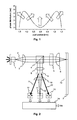
- the thickness of the substrate of the recording medium is constant over the whole recording medium, the light reflected from the recording medium has a nearly flat phase profile. If, however, there are deviations in the thickness of the substrate, this wavefront assumes a donut shaped profile with spatially varying phase gradients.
- the phase distribution of such a wavefront is depicted in Fig. 1.
- the direction of propagation i.e. the angle of the optical rays, is perpendicular to the local phase gradient, as indicated by the arrows.
- the arrows are not to scale.
- Fig. 2 schematically depicts an optical pickup for a multi-layer optical recording medium capable of measuring spherical aberration.
- the pickup largely corresponds to a standard pickup. However, additional elements are provided for measuring the spherical aberration.
- a laser diode 1 emits a linearly polarized light beam 2 along an optical axis.
- the light beam 2 is collimated by a collimator 3 and passes a polarizing beam splitter 4 and a quarter-wave plate 5, which transforms the linear polarization of the light beam 2 into a circular polarization.
- the light beam 2 is then focused onto a recording medium 7 having a cover layer 7a by a focusing lens 6. A part of the light beam 2 is reflected from the recording medium 7 and collimated by the focusing lens 6.
- the reflected light beam 2 passes the quarter-wave plate 5, its circular polarization is transformed to a linear polarization.
- the direction of polarization of the reflected light beam 2 after passing the quarter-wave plate 5 is perpendicular to the direction of polarization of the initial light beam 2. Therefore, the reflected light beam 2 is now reflected by the polarizing beam splitter 4 towards a detector arrangement 11, 12, 13.
- a further focusing lens 8 focuses the light beam 2 through a cylindrical lens 10 onto a four-quadrant detector 11 for standard tracking and focusing control.
- a special beam splitter 9 splits the light beam 2 returning from the recording medium into three beams 20, 21, 22.
- the main beam 20, which carries about 90% of the energy, is focused onto the four-quadrant detector 11.
- the two remaining beams 21, 22 are focused on position sensitive two-quadrant detectors 12, 13.
- the first two-quadrant detector 12 generates the signals A and B
- the second two-quadrant detector 13 the signals C and D.
- a signal processor 14 determines the propagation direction of the beams.
- this measurement method corresponds to a very simple Shack-Hartmann wavefront sensor. Due to the design of the beam splitter 9 and the positioning of the detectors 12, 13 the normalized difference signal SA is equal to zero for a collimated wave without spherical aberration. When spherical aberration is present, the spots on the two-quadrant detectors 12, 13 move and the absolute value of the normalized difference signal SA is larger than zero. As the sign of normalized difference signal SA depends on the sign of the spherical aberration, the normalized difference signal SA can be used as a control signal for a spherical aberration corrector (not shown).
- the special beam splitter 9 is shown in Fig. 3 in more detail, whereby part a) of the figure shows a side view, while part b) shows a top view of the beam splitter 9.
- the beam splitter mainly consists of two small prisms 91, 92, which are fixed on a flat glass substrate 93.
- the prisms 91, 92 are arranged symmetrically to the optical axis of the light beam 2. Light falling within the regions of the prisms 91, 92 is deviated by a fixed angle. The remaining light is transmitted straight through the beam splitting element 9.
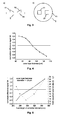
- FIG. 4 A simulation of the normalized difference signal SA as a function of the thickness of the cover layer of the recording medium, which was obtained with the help of a ray tracing program, is shown in Fig. 4.
- a focusing lens 6 having a numerical aperture of 0.85 and being corrected for a cover layer thickness of 100 ⁇ m was assumed.
- the astigmatic focus control signal was set equal to zero by adapting the position of a focus actuator, i.e. the distance of the focusing lens 6 from the recording medium.
- the simulation shows that the sign of the normalized difference signal SA depends on the sign of the cover layer thickness deviation, and that the signal is suitable for controlling a spherical aberration correcting element.
- Fig. 5 the normalized difference signal SA (left axis, solid line) is depicted as a function of the focal length of a liquid-crystal lens, which is used for correcting the spherical aberration.
- the figure further shows the wavefront error in the focal spot on the recording medium (right axis, dotted line).
- the small offset of the normalized difference signal SA at the position of minimum wavefront error (at 298 mm) can be corrected electronically.
- Fig. 6 An approach according to the invention for measuring the spherical aberration is shown in Fig. 6.
- the special beam splitter is replaced by a special volume hologram 15.
- three additional detectors 16,17,18 are used, generating the signals A, B and C, respectively.
- volume holograms can be used to correlate wavefronts with stored patterns. By storing wavefront patterns with various degrees of spherical aberration, it is possible to determine the amount of spherical aberration of an impinging wavefront.
- the hologram is preferably designed as follows. Most of the light (>90%) is transmitted through the hologram.
- the wavefront passing through the hologram 15 has a positive spherical aberration, 1-2% of the light are focused on the first detector 16. If the wavefront passing through the hologram 15 has no spherical aberration, 1-2% of the light are focused on the second detector 17. If the wavefront passing through the hologram 15 has a negative spherical aberration, 1-2% of the light are focused on the third detector 18.
- a control signal for a spherical aberration corrector is generated.
- the hologram 15 is located directly on the focusing lens 6.
- the main difficulty for this technique is the initial design of the hologram 15. Once the design is done the volume hologram 15 can easily be mass produced by replication in plastic.
Landscapes
- Physics & Mathematics (AREA)
- Optics & Photonics (AREA)
- General Physics & Mathematics (AREA)
- Optical Head (AREA)
- Optical Recording Or Reproduction (AREA)
- Testing Of Optical Devices Or Fibers (AREA)
Abstract
Claims (5)
- Méthode permettant de déterminer une aberration sphérique dans un faisceau lumineux (2), comprenant les étapes consistant à :- séparer le faisceau lumineux (2) en au moins deux faisceaux lumineux partiels (20, 23, 24, 25) ;- focaliser les faisceaux lumineux partiels (20, 23, 24, 25) sur les détecteurs respectifs (11, 16, 17, 18), où au moins un signal (A, B, C) généré par les détecteurs (16, 17, 18) dépend des emplacements du faisceau lumineux partiel respectif (23, 24, 25) ; et- déterminer l'aberration sphérique à l'aide des signaux (A, B, C) générés par les détecteurs (16, 17, 18) ;caractérisée en ce que un hologramme de volume (15) stockant des modèles de front d'onde présentant plusieurs degrés d'aberration sphérique est fourni afin de séparer le faisceau lumineux (2) en faisceaux lumineux partiels (20, 23, 24, 25).
- Méthode selon la revendication 1, caractérisée en ce que les faisceaux partiels (23, 24, 25) sont focalisés sur les détecteurs respectifs (16, 17, 18) en fonction du niveau d'aberration sphérique dans le faisceau lumineux (2).
- Dispositif permettant de déterminer une aberration sphérique dans un faisceau lumineux (2), comprenant :- un moyen pour séparer le faisceau lumineux (2) en au moins deux faisceaux lumineux partiels (20, 23, 24, 25) ;- un moyen de focalisation (8) pour focaliser les faisceaux lumineux partiels (20, 23, 24, 25) sur des détecteurs respectifs (11, 16, 17, 18) ; et- un processeur de signaux (14) pour déterminer l'aberration sphérique à l'aide des signaux (A, B, C) générés par les détecteurs (16, 17, 18)caractérisé en ce que ledit moyen pour séparer le faisceau lumineux (2) est un hologramme de volume (15) stockant des modèles de front d'onde présentant plusieurs degrés d'aberration sphérique.
- Dispositif selon la revendication 3, dans lequel les faisceaux partiels (23, 24, 25) sont focalisés sur les détecteurs respectifs (16, 17, 18) en fonction du niveau de l'aberration sphérique du faisceau lumineux (2).
- Appareil pour lire et/ou écrire sur des supports d'enregistrement optique,
caractérisé en ce qu'il comprend des moyens pour exécuter une méthode selon une quelconque des revendications 1 ou 2 ou comprend un dispositif selon une des revendications 3 ou 4 permettant de déterminer une aberration sphérique.
Priority Applications (1)
| Application Number | Priority Date | Filing Date | Title |
|---|---|---|---|
| EP04797691A EP1702325B1 (fr) | 2004-01-08 | 2004-11-06 | Méthode pour determiner l'aberration sphérique |
Applications Claiming Priority (3)
| Application Number | Priority Date | Filing Date | Title |
|---|---|---|---|
| EP04000258A EP1553574A1 (fr) | 2004-01-08 | 2004-01-08 | Méthode pour déterminer l'aberration sphérique |
| EP04797691A EP1702325B1 (fr) | 2004-01-08 | 2004-11-06 | Méthode pour determiner l'aberration sphérique |
| PCT/EP2004/012593 WO2005069280A2 (fr) | 2004-01-08 | 2004-11-06 | Procede de determination de l'aberration spherique |
Publications (2)
| Publication Number | Publication Date |
|---|---|
| EP1702325A2 EP1702325A2 (fr) | 2006-09-20 |
| EP1702325B1 true EP1702325B1 (fr) | 2008-01-23 |
Family
ID=34585955
Family Applications (2)
| Application Number | Title | Priority Date | Filing Date |
|---|---|---|---|
| EP04000258A Withdrawn EP1553574A1 (fr) | 2004-01-08 | 2004-01-08 | Méthode pour déterminer l'aberration sphérique |
| EP04797691A Expired - Lifetime EP1702325B1 (fr) | 2004-01-08 | 2004-11-06 | Méthode pour determiner l'aberration sphérique |
Family Applications Before (1)
| Application Number | Title | Priority Date | Filing Date |
|---|---|---|---|
| EP04000258A Withdrawn EP1553574A1 (fr) | 2004-01-08 | 2004-01-08 | Méthode pour déterminer l'aberration sphérique |
Country Status (7)
| Country | Link |
|---|---|
| US (1) | US7633613B2 (fr) |
| EP (2) | EP1553574A1 (fr) |
| JP (1) | JP2007518206A (fr) |
| KR (1) | KR20060134014A (fr) |
| CN (1) | CN100463059C (fr) |
| DE (1) | DE602004011567T2 (fr) |
| WO (1) | WO2005069280A2 (fr) |
Families Citing this family (4)
| Publication number | Priority date | Publication date | Assignee | Title |
|---|---|---|---|---|
| DE102004002181B4 (de) | 2004-01-15 | 2011-08-18 | Infineon Technologies AG, 81669 | Integrierter Transistor, insbesondere für Spannungen größer 40 Volt, und Herstellungsverfahren |
| EP1964120B1 (fr) * | 2005-11-21 | 2010-01-06 | Ricoh Company, Ltd. | Unité source de lumière, unité de détection optique, dispositif lecteur optique et dispositif à disque optique |
| WO2009088146A1 (fr) * | 2008-01-11 | 2009-07-16 | Samsung Electronics Co, . Ltd. | Appareil et procédé de lecture d'image |
| WO2021112302A1 (fr) * | 2019-12-06 | 2021-06-10 | 전자부품연구원 | Procédé d'enregistrement d'un élément optique holographique pour affichage tête haute |
Family Cites Families (10)
| Publication number | Priority date | Publication date | Assignee | Title |
|---|---|---|---|---|
| WO1996028816A2 (fr) * | 1995-03-15 | 1996-09-19 | Philips Electronics N.V. | Dispositif pour la lecture optique d'un support d'enregistrement |
| DE19715443A1 (de) * | 1997-04-14 | 1998-10-15 | Wil Van Bladel | Ansteckclip |
| JPH11306579A (ja) * | 1998-04-15 | 1999-11-05 | Sony Corp | ビームスプリッタ及び光ピックアップ装置 |
| EP0984440A3 (fr) * | 1998-09-04 | 2000-05-24 | Matsushita Electric Industrial Co., Ltd. | Système de détection d'aberration et appareil d'enregistrement et de reproduction d'information optique |
| JP2000182254A (ja) * | 1998-12-15 | 2000-06-30 | Pioneer Electronic Corp | ピックアップ装置 |
| JP4085812B2 (ja) * | 2000-09-06 | 2008-05-14 | 株式会社日立製作所 | 光ヘッドおよび光ディスク装置 |
| JP3827940B2 (ja) * | 2000-11-15 | 2006-09-27 | シャープ株式会社 | 収差検出装置および光ピックアップ装置 |
| JP2002163830A (ja) * | 2000-11-24 | 2002-06-07 | Toshiba Corp | 光学的収差を利用した光情報処理システムおよび厚みムラのある透明層で保護された記録層を持つ情報媒体 |
| JP4505982B2 (ja) * | 2000-11-30 | 2010-07-21 | 三菱電機株式会社 | 光ヘッド装置、記録及び/又は再生装置並びに記録及び/又は再生方法 |
| JP3819756B2 (ja) * | 2001-10-23 | 2006-09-13 | 富士通株式会社 | 光情報処理装置 |
-
2004
- 2004-01-08 EP EP04000258A patent/EP1553574A1/fr not_active Withdrawn
- 2004-11-06 EP EP04797691A patent/EP1702325B1/fr not_active Expired - Lifetime
- 2004-11-06 WO PCT/EP2004/012593 patent/WO2005069280A2/fr not_active Ceased
- 2004-11-06 CN CNB2004800383357A patent/CN100463059C/zh not_active Expired - Fee Related
- 2004-11-06 JP JP2006548125A patent/JP2007518206A/ja not_active Abandoned
- 2004-11-06 DE DE602004011567T patent/DE602004011567T2/de not_active Expired - Lifetime
- 2004-11-06 US US10/585,536 patent/US7633613B2/en not_active Expired - Fee Related
- 2004-11-06 KR KR1020067013544A patent/KR20060134014A/ko not_active Ceased
Non-Patent Citations (1)
| Title |
|---|
| None * |
Also Published As
| Publication number | Publication date |
|---|---|
| WO2005069280A2 (fr) | 2005-07-28 |
| WO2005069280A3 (fr) | 2005-11-03 |
| EP1553574A1 (fr) | 2005-07-13 |
| JP2007518206A (ja) | 2007-07-05 |
| DE602004011567T2 (de) | 2009-02-05 |
| CN100463059C (zh) | 2009-02-18 |
| CN1902691A (zh) | 2007-01-24 |
| DE602004011567D1 (de) | 2008-03-13 |
| EP1702325A2 (fr) | 2006-09-20 |
| US20090185180A1 (en) | 2009-07-23 |
| KR20060134014A (ko) | 2006-12-27 |
| US7633613B2 (en) | 2009-12-15 |
Similar Documents
| Publication | Publication Date | Title |
|---|---|---|
| US6353582B1 (en) | Pickup device | |
| EP1553570B1 (fr) | Tete optique et unite de disque optique | |
| JP3765235B2 (ja) | 光ディスク装置 | |
| EP0398431B1 (fr) | Lentille d'objectif rétrofocal et dispositif de balayage optique muni d'une telle lentille | |
| US8014257B2 (en) | Extraction optical system and optical head device including the same | |
| JP2019168313A (ja) | 光学式高さ計測用光モジュール | |
| EP1702325B1 (fr) | Méthode pour determiner l'aberration sphérique | |
| GB2247099A (en) | Optical system using polarized light. | |
| US6730896B1 (en) | Optical pickup device | |
| KR20070104451A (ko) | 다중빔 광학주사장치의 스폿 사이즈 초점 오차 검출 | |
| TWI249740B (en) | Optical head and optical disk drive | |
| JP2004144702A (ja) | 変位検出方法、変位検出装置および情報記録媒体原盤記録装置 | |
| EP2017837A2 (fr) | Dispositif de capture optique | |
| JPH10105996A (ja) | 光学記録媒体へ記録し又は該媒体から再生するための記録又は再生装置 | |
| US20070171786A1 (en) | Optical pickup apparatus and optical disk apparatus | |
| US20090109825A1 (en) | Optical scanning device | |
| US7130134B2 (en) | Optical scanning device | |
| JP4301130B2 (ja) | 光学ピックアップ | |
| KR100626966B1 (ko) | 홀로그래픽 롬 재생 시스템의 서보 장치 | |
| KR100657665B1 (ko) | 나이프 에지를 이용한 홀로그래픽 롬 재생 시스템의 서보장치 | |
| EP1489604A1 (fr) | Procédé de détection d'aberration sphérique | |
| JP3986521B2 (ja) | 光ディスク装置 | |
| JP2002329336A (ja) | 光ヘッド及び光ディスク装置 | |
| JP2005302254A (ja) | 球面収差検出補正装置 | |
| JP2012094225A (ja) | 光ディスク装置 |
Legal Events
| Date | Code | Title | Description |
|---|---|---|---|
| PUAI | Public reference made under article 153(3) epc to a published international application that has entered the european phase |
Free format text: ORIGINAL CODE: 0009012 |
|
| 17P | Request for examination filed |
Effective date: 20060511 |
|
| AK | Designated contracting states |
Kind code of ref document: A2 Designated state(s): DE FR GB |
|
| DAX | Request for extension of the european patent (deleted) | ||
| RBV | Designated contracting states (corrected) |
Designated state(s): DE FR GB |
|
| GRAC | Information related to communication of intention to grant a patent modified |
Free format text: ORIGINAL CODE: EPIDOSCIGR1 |
|
| GRAP | Despatch of communication of intention to grant a patent |
Free format text: ORIGINAL CODE: EPIDOSNIGR1 |
|
| GRAS | Grant fee paid |
Free format text: ORIGINAL CODE: EPIDOSNIGR3 |
|
| GRAA | (expected) grant |
Free format text: ORIGINAL CODE: 0009210 |
|
| AK | Designated contracting states |
Kind code of ref document: B1 Designated state(s): DE FR GB |
|
| REG | Reference to a national code |
Ref country code: GB Ref legal event code: FG4D |
|
| REF | Corresponds to: |
Ref document number: 602004011567 Country of ref document: DE Date of ref document: 20080313 Kind code of ref document: P |
|
| REG | Reference to a national code |
Ref country code: GB Ref legal event code: 746 Effective date: 20080229 |
|
| ET | Fr: translation filed | ||
| PLBE | No opposition filed within time limit |
Free format text: ORIGINAL CODE: 0009261 |
|
| STAA | Information on the status of an ep patent application or granted ep patent |
Free format text: STATUS: NO OPPOSITION FILED WITHIN TIME LIMIT |
|
| 26N | No opposition filed |
Effective date: 20081024 |
|
| PGFP | Annual fee paid to national office [announced via postgrant information from national office to epo] |
Ref country code: DE Payment date: 20091118 Year of fee payment: 6 |
|
| PGFP | Annual fee paid to national office [announced via postgrant information from national office to epo] |
Ref country code: FR Payment date: 20091208 Year of fee payment: 6 Ref country code: GB Payment date: 20091124 Year of fee payment: 6 |
|
| GBPC | Gb: european patent ceased through non-payment of renewal fee |
Effective date: 20101106 |
|
| REG | Reference to a national code |
Ref country code: FR Ref legal event code: ST Effective date: 20110801 |
|
| REG | Reference to a national code |
Ref country code: DE Ref legal event code: R119 Ref document number: 602004011567 Country of ref document: DE Effective date: 20110601 Ref country code: DE Ref legal event code: R119 Ref document number: 602004011567 Country of ref document: DE Effective date: 20110531 |
|
| PG25 | Lapsed in a contracting state [announced via postgrant information from national office to epo] |
Ref country code: FR Free format text: LAPSE BECAUSE OF NON-PAYMENT OF DUE FEES Effective date: 20101130 |
|
| PG25 | Lapsed in a contracting state [announced via postgrant information from national office to epo] |
Ref country code: GB Free format text: LAPSE BECAUSE OF NON-PAYMENT OF DUE FEES Effective date: 20101106 |
|
| PG25 | Lapsed in a contracting state [announced via postgrant information from national office to epo] |
Ref country code: DE Free format text: LAPSE BECAUSE OF NON-PAYMENT OF DUE FEES Effective date: 20110531 |