EP1702556A1 - Endoscope et dispositif de traitement d'images spectrales - Google Patents
Endoscope et dispositif de traitement d'images spectrales Download PDFInfo
- Publication number
- EP1702556A1 EP1702556A1 EP06005419A EP06005419A EP1702556A1 EP 1702556 A1 EP1702556 A1 EP 1702556A1 EP 06005419 A EP06005419 A EP 06005419A EP 06005419 A EP06005419 A EP 06005419A EP 1702556 A1 EP1702556 A1 EP 1702556A1
- Authority
- EP
- European Patent Office
- Prior art keywords
- image
- spectral image
- spectroscopic characteristic
- characteristic information
- endoscope
- Prior art date
- Legal status (The legal status is an assumption and is not a legal conclusion. Google has not performed a legal analysis and makes no representation as to the accuracy of the status listed.)
- Granted
Links
Images



Classifications
-
- A—HUMAN NECESSITIES
- A61—MEDICAL OR VETERINARY SCIENCE; HYGIENE
- A61B—DIAGNOSIS; SURGERY; IDENTIFICATION
- A61B1/00—Instruments for performing medical examinations of the interior of cavities or tubes of the body by visual or photographical inspection, e.g. endoscopes; Illuminating arrangements therefor
- A61B1/00002—Operational features of endoscopes
- A61B1/00004—Operational features of endoscopes characterised by electronic signal processing
- A61B1/00009—Operational features of endoscopes characterised by electronic signal processing of image signals during a use of endoscope
-
- A—HUMAN NECESSITIES
- A61—MEDICAL OR VETERINARY SCIENCE; HYGIENE
- A61B—DIAGNOSIS; SURGERY; IDENTIFICATION
- A61B1/00—Instruments for performing medical examinations of the interior of cavities or tubes of the body by visual or photographical inspection, e.g. endoscopes; Illuminating arrangements therefor
- A61B1/04—Instruments for performing medical examinations of the interior of cavities or tubes of the body by visual or photographical inspection, e.g. endoscopes; Illuminating arrangements therefor combined with photographic or television appliances
- A61B1/045—Control thereof
-
- A—HUMAN NECESSITIES
- A61—MEDICAL OR VETERINARY SCIENCE; HYGIENE
- A61B—DIAGNOSIS; SURGERY; IDENTIFICATION
- A61B1/00—Instruments for performing medical examinations of the interior of cavities or tubes of the body by visual or photographical inspection, e.g. endoscopes; Illuminating arrangements therefor
- A61B1/04—Instruments for performing medical examinations of the interior of cavities or tubes of the body by visual or photographical inspection, e.g. endoscopes; Illuminating arrangements therefor combined with photographic or television appliances
- A61B1/05—Instruments for performing medical examinations of the interior of cavities or tubes of the body by visual or photographical inspection, e.g. endoscopes; Illuminating arrangements therefor combined with photographic or television appliances characterised by the image sensor, e.g. camera, being in the distal end portion
-
- A—HUMAN NECESSITIES
- A61—MEDICAL OR VETERINARY SCIENCE; HYGIENE
- A61B—DIAGNOSIS; SURGERY; IDENTIFICATION
- A61B5/00—Measuring for diagnostic purposes; Identification of persons
- A61B5/0059—Measuring for diagnostic purposes; Identification of persons using light, e.g. diagnosis by transillumination, diascopy, fluorescence
- A61B5/0075—Measuring for diagnostic purposes; Identification of persons using light, e.g. diagnosis by transillumination, diascopy, fluorescence by spectroscopy, i.e. measuring spectra, e.g. Raman spectroscopy, infrared absorption spectroscopy
-
- H—ELECTRICITY
- H04—ELECTRIC COMMUNICATION TECHNIQUE
- H04N—PICTORIAL COMMUNICATION, e.g. TELEVISION
- H04N1/00—Scanning, transmission or reproduction of documents or the like, e.g. facsimile transmission; Details thereof
- H04N1/46—Colour picture communication systems
- H04N1/64—Systems for the transmission or the storage of the colour picture signal; Details therefor, e.g. coding or decoding means therefor
- H04N1/646—Transmitting or storing colour television type signals, e.g. PAL, Lab; Their conversion into additive or subtractive colour signals or vice versa therefor
-
- H—ELECTRICITY
- H04—ELECTRIC COMMUNICATION TECHNIQUE
- H04N—PICTORIAL COMMUNICATION, e.g. TELEVISION
- H04N23/00—Cameras or camera modules comprising electronic image sensors; Control thereof
- H04N23/10—Cameras or camera modules comprising electronic image sensors; Control thereof for generating image signals from different wavelengths
- H04N23/12—Cameras or camera modules comprising electronic image sensors; Control thereof for generating image signals from different wavelengths with one sensor only
-
- H—ELECTRICITY
- H04—ELECTRIC COMMUNICATION TECHNIQUE
- H04N—PICTORIAL COMMUNICATION, e.g. TELEVISION
- H04N23/00—Cameras or camera modules comprising electronic image sensors; Control thereof
- H04N23/50—Constructional details
- H04N23/555—Constructional details for picking-up images in sites, inaccessible due to their dimensions or hazardous conditions, e.g. endoscopes or borescopes
-
- H—ELECTRICITY
- H04—ELECTRIC COMMUNICATION TECHNIQUE
- H04N—PICTORIAL COMMUNICATION, e.g. TELEVISION
- H04N23/00—Cameras or camera modules comprising electronic image sensors; Control thereof
- H04N23/70—Circuitry for compensating brightness variation in the scene
- H04N23/74—Circuitry for compensating brightness variation in the scene by influencing the scene brightness using illuminating means
-
- H—ELECTRICITY
- H04—ELECTRIC COMMUNICATION TECHNIQUE
- H04N—PICTORIAL COMMUNICATION, e.g. TELEVISION
- H04N23/00—Cameras or camera modules comprising electronic image sensors; Control thereof
- H04N23/80—Camera processing pipelines; Components thereof
- H04N23/84—Camera processing pipelines; Components thereof for processing colour signals
- H04N23/85—Camera processing pipelines; Components thereof for processing colour signals for matrixing
-
- A—HUMAN NECESSITIES
- A61—MEDICAL OR VETERINARY SCIENCE; HYGIENE
- A61B—DIAGNOSIS; SURGERY; IDENTIFICATION
- A61B5/00—Measuring for diagnostic purposes; Identification of persons
- A61B5/0059—Measuring for diagnostic purposes; Identification of persons using light, e.g. diagnosis by transillumination, diascopy, fluorescence
- A61B5/0082—Measuring for diagnostic purposes; Identification of persons using light, e.g. diagnosis by transillumination, diascopy, fluorescence adapted for particular medical purposes
- A61B5/0084—Measuring for diagnostic purposes; Identification of persons using light, e.g. diagnosis by transillumination, diascopy, fluorescence adapted for particular medical purposes for introduction into the body, e.g. by catheters
Definitions
- the present invention relates to an endoscope system apparatus, particularly relates to a constitution used in a medical field for forming and displaying a spectral image (image) comprising image information of an arbitrary selected wavelength region.
- three band pass filters of narrow (wavelength) bands are provided in place of a rotating filter of R (red), G (green), B (blue) of a face sequential type, and a spectral image is formed by successively outputting illuminating light by way of the narrow band path filters and processing three signals provided by the illuminating light while changing respective weights thereof similar to a case of R, G, B (RGB) signals.
- a spectral image in the digesting organ of the stomach, the large intestine or the like, a fine structure which cannot be provided in a background art is extracted.
- a relationship between respective color sensitivity characteristics of RGB which are formed into numerical value data and a spectroscopic characteristic of a specific narrow band pass filter which is formed into numerical value data is calculated as matrix data (coefficient set) and by operation of the matrix data and RGB signals, a spectral image signal provided by way of the narrow band pass filter is pseudonically provided.
- a spectral image extracting a specific fine structure or the like of an object it is necessary to select a preferable wavelength region or adjusting the selected wavelength region and there is a case in which a necessary and sufficient spectral image cannot be provided in inspection by an endoscope in a limited time period. Further, it is necessary to observe and diagnose the spectral image in details by comparing with a normal color image and when a spectral image having an arbitrary wavelength region can be formed and displayed after inspection by the endoscope, an apparatus having an excellent way of use can be provided.
- color image signals of RGB constituting a basis thereof differs by a spectroscopic sensitivity characteristic including a kind of a color filter of an imaging element (solid state image sensor or the like), a kind of a light source, a spectroscopic sensitivity characteristic of an optical system member of the endoscope of a light guide or the like to pose a problem that such differences in the spectroscopic characteristics of the endoscope of the light source effect an influence on reproducibility on the same wavelength region.
- Fig.9 shows an example of spectroscopic sensitivity characteristics of color filters of primary color type CCD, respective spectroscopic sensitivities of the R, G, B color filters differ by an individual difference of CCD, in an operation processing using a single matrix data, the difference in the spectroscopic characteristics is reflected to an operation result and the spectral image having reproducibility cannot be provided.
- a spectroscopic characteristic of illuminating light differs by an aperture amount of a diaphragm blade in the light source apparatus owing to chromatic aberration of lenses, there is constituted a characteristic in which the more the light amount is reduced, the more the red color component is gradually cut from a long wavelength side to pose a problem that the reproducibility of the spectral image is deteriorated even by the spectroscopic characteristic of the illuminating light.
- An object of an illustrative, non-limiting embodiment of the present invention is to provide an endoscope spectral image system apparatus capable of forming and displaying a spectral image of an arbitrary wavelength region after inspection by an endoscope, capable of forming a spectral image having excellent reproducibility in the same wavelength region even when a. spectroscopic characteristic of an imaging element or an endoscope or a spectroscopic characteristic of a light source or illuminating light differs and having an excellent way of use.
- the spectroscopic characteristic information is supplied from the signal processor to the image recording apparatus along with the normal color image data, at the image recording apparatus, the matrix data (coefficient set) in correspondence with the spectroscopic characteristic information is read from the plurality of matrix data stored to the storing portion, and the spectral image is formed by the matrix operation based on the data.
- the matrix data includes coefficients for calculating ⁇ 1, ⁇ 2, ⁇ 3 signals of wavelength narrow bands (components) by the matrix operation from, for example, RGB signals (may be other signals), or 61 of wavelength region parameters (coefficient sets p1 through p61) constituted by dividing a wavelength region from 400nm to 700nm by an interval of 5nm, and a plurality of table data comprising 61 of the coefficient sets are prepared in accordance with the spectroscopic characteristic.
- ⁇ 1, ⁇ 2, ⁇ 3 signals are formed from matrix data (coefficient set) in correspondence with the three wavelength regions and the RGB signals output from DVP, DSP ort the like, the spectral image having excellent reproducibility is formed by the ⁇ 1, ⁇ 2, ⁇ 3 signals and displayed on a monitor or the like. That is, according to the image recording apparatus, not only the recorded normal image (stationary picture and dynamic picture) is reproduced and displayed, but also, based on the normal image, the spectral image (stationary picture and dynamic picture) in consideration of the spectroscopic characteristic of the endoscope (CCD) can be generated and displayed.
- CCD spectroscopic characteristic of the endoscope
- the matrix data in accordance with a difference of the spectroscopic characteristic of a Xenon lamp or a halogen lamp is read, according to the constitution of Claim 3, the matrix data divided by, for example, 6 stages, in accordance with the diaphragm position (state) and in accordance with the spectroscopic characteristics of the 6 stages is read, the spectral image in accordance with the spectroscopic characteristics is formed and therefore, the reproducibility is further improved.
- the spectral image of the arbitrary wavelength region can be formed and displayed and object image information useful for diagnosis or the like can be provided. Further, even when the spectroscopic characteristic of the imaging element or the endoscope taking the image of the normal color image, or the spectroscopic characteristic of the light source or the illuminating light differs, the spectral image having the excellent reproducibility which is not influenced by the differences of the spectroscopic characteristics can be formed and the apparatus having an excellent way of use can be provided.
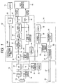
- Fig.1 through Figs.4A and 4B show a constitution of an endoscope (electronic endoscope) spectral image system apparatus according to an exemplary embodiment, as shown by Fig. 1, the apparatus is constituted to connect a scope (electronic endoscope) 10 detachably from a processor apparatus 12 and a light source apparatus 14, the processor apparatus 12 is connected with a monitor 15 and an image recording apparatus (or filing apparatus) 16, and the monitor 15 is connected also to the image recording and displaying (recording and reproducing) apparatus 16.
- the image recording apparatus 16 can be constituted by a personal computer or the like having a keyboard, a mouse. Further, there is also a case in which the light source apparatus 14 is integrally constituted with the processor apparatus 12, further, there is also a case in which a main signal processing circuit at inside of the processing apparatus 12 is arranged at the scope 10.
- the scope 10 is provided with CCD 18 constituting a solid state image sensor at a front end portion thereof, as the CCD 18, for example, a complementally color type having color filters of Mg (magenta), Ye (yellow), Cy (cyan), G (green) or a primary color type having color filters of RGB is used at an image taking face thereof.
- the CCD 18 is provided with a CCD driving circuit 19 for forming a drive pulse based on a synchronizing signal output from a timing generator (TG) 20 and is provided with a CDS/AGC (correlated double sampling/automatic gain control) circuit 21 for sampling and amplifying a picture image (image) signal input from the CCD 18, an A/D converter 22.
- TG timing generator
- CDS/AGC correlated double sampling/automatic gain control
- a microcomputer 24 for controlling various circuits in the scope 10 and communicating with a second microcomputer (42) at inside of the processor apparatus 12, and a memory (ROM or the like) 25 for storing a spectroscopic characteristic (spectroscopic characteristic in primary color type, complementary color type) of CCD 18, spectroscopic characteristic information of the scope 10 including spectroscopic characteristics or the like of an abject optical system, optical system members including a light guide and other identifying information are arranged.
- the scope 10 is provided with an illuminating window 26 at a front end thereof, and the illuminating window 26 is connected to the light source apparatus 14 by a light guide 27.
- the processor apparatus 12 is provided with a DVP (digital video processor) 30 for subjecting an image signal converted into digital to various image processing, and at the DVP 30, a Y/C signal constituted by a brightness (Y) signal and a chrominance [C (R-Y, B-Y)] signal is formed from an output signal of the CCD 18 and output.
- DVP digital video processor
- a normal image (dynamic picture and stationary picture) and a spectral image (dynamic picture and stationary picture) can selectively be formed and displayed
- the DVP 30 is connected with a signal processing circuit 32 for forming a normal image by way of a switch 31 (at one terminal) for switching whether the normal image is formed or the spectral image is formed
- the signal processing circuit 32 carries out a signal processing of character mix or the like for adding an image taking condition, patient information or the like to the image signal data.
- Other terminal of the switch 31 is arranged with a spectral image-forming circuit 34A for forming the spectral image at inside of the processor apparatus 12, a D/A converter 35 for inputting both outputs of the circuit 34A and the signal processing circuit 32, and an output of the D/A converter 35 is supplied to the monitor 15.
- the signal processing circuit 32 is arranged with an image memory 38 for temporarily holding a stationary picture, a packet generating circuit 39 for correlating the stationary picture and the spectroscopic characteristic information, and a network I/F (interface) 40 as a constitution for outputting the stationary picture to the image recording apparatus 16.
- the processor apparatus 12 is provided with the second microcomputer 42 for controlling an inner circuit thereof and communicating with the first microcomputer 24, a third microcomputer 43 for carrying out similar processing, a memory 44 (ROM or the like) for storing operation information at inside of the processor apparatus 12, matrix data (Table) for forming the spectral image based on RGB signals, a serial I/F (interface) 45 for outputting a dynamic picture, the dynamic picture and the spectroscopic characteristic information are output from the serial I/F 45 and a packet for the stationary picture is output from network I/F 40.
- ROM read only memory
- Table matrix data
- serial I/F interface
- scope side spectroscopic characteristic information (data) stored to the memory 25 of the scope 10 is transmitted from the first microcomputer 24 to the third microcomputer 43 by way of the second microcomputer 42, the stationary picture is added to image data at the packet generating circuit 39 and the dynamic picture is transmitted by the serial I/F 45. Therefore, the first microcomputer 24 through the third microcomputer 43 (and fourth microcomputer 50), the packet generating circuit 39 and the interfaces 40, 45 constitute information-outputting circuits. Further, the matrix data stored to the memory 44 is read by the second microcomputer 42 and is provided to the spectral image-forming circuit 34A.
- the light source apparatus 14 is provided with a light converging lens 48 for outputting illuminating light to the light guide 27, a diaphragm (blade) 49, a light source lamp (Xenon lamp or halogen lamp) 50, a lamp driving circuit 51 and a diaphragm position sensor 52 for detecting a drive diaphragm position of the diaphragm 49, and arranged with a memory (ROM or the like) 55 for storing information with regard to the fourth microcomputer 54, a kind of the light source lamp 50 or the like.
- ROM read only memory
- the fourth microcomputer 54 supplies the diaphragm position information (or spectroscopic characteristic information in correspondence with the diaphragm position), information of whether the light source lamp 50 is a Xenon lamp or a halogen lamp (or spectroscopic characteristic information in correspondence with the kind of lamp) to the second microcomputer 42, and the information is transmitted to the image recording apparatus 16 along with other spectroscopic characteristic information by being supplied to the third microcomputer 43.
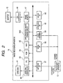
- Fig.2 shows an inner constitution of the image recording and displaying (reproducing) apparatus 16, inside of the apparatus 16 is provided with interfaces of a network I/F 57 for inputting a packet for the stationary picture, a serial I/F 58 for inputting spectroscopic characteristic information in recording the dynamic picture, a video grabber 59 for capturing the normal color image data of the dynamic picture, a keyboard I/F (interface) 60a, a mouse I/F 60b, which are connected to the processor apparatus 12, and the interfaces are connected to respective circuits, mentioned later, by way of a data path.
- a network I/F 57 for inputting a packet for the stationary picture
- serial I/F 58 for inputting spectroscopic characteristic information in recording the dynamic picture
- a video grabber 59 for capturing the normal color image data of the dynamic picture
- a keyboard I/F (interface) 60a keyboard I/F (interface) 60a
- a mouse I/F 60b which are connected to the processor apparatus 12, and the interface
- the image recording apparatus 16 not only the recorded normal image (both of the stationary picture and the dynamic picture) is reproduced and displayed but also the spectral image (both of the stationary picture and the dynamic picture) is formed based on the normal image to display and operation therefor is carried out by a keyboard or a mouse.
- the image recording apparatus 16 is provided with a hard disk 61 for storing the image, a hard disk controller 62, CPU (or microcomputer) 63 for governing to control respective circuits, ROM (Read Only Memory) 64 for storing the matrix data for forming the spectral image from the RGB signals and a plurality of matrix data (table data) in correspondence with the spectroscopic characteristic information output from the processor apparatus 12, RAM (Readable Writable Memory) 65 for inputting to process data or the like, a spectral image-forming circuit 34B for forming the spectral image by using the read matrix data, a frame memory 67 for a monitor display processing and a D/A converter 68, and an output to the D/A converter 68 is supplied to the monitor 15.
- ROM Read Only Memory
- RAM Readable Writable Memory
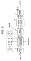
- Fig.3 shows an inner constitution of the spectral image-forming circuit 34A, 34B arranged at the processor 12 and the image recording apparatus 16, the spectral image-forming circuit 34A, 34B is provided with a first color converting circuit 70 for converting the brightness (Y)/chrominance (C) signal into the RGB signals, a color space conversion processing circuit 71 for carrying out matrix operation for the spectral image with regard to the RGB signals, and the color space conversion processing circuit 71 outputs spectral image signals of selected wavelength regions ⁇ 1, ⁇ 2, ⁇ 3.
- a first color converting circuit 70 for converting the brightness (Y)/chrominance (C) signal into the RGB signals
- the color space conversion processing circuit 71 outputs spectral image signals of selected wavelength regions ⁇ 1, ⁇ 2, ⁇ 3.
- the matrix data (one table) used in the matrix operation of the color space conversion processing circuit 71 and stored to the memory 44, the ROM 64 is as shown by Table 1, shown below.
- Table I Parameter k pr k pg k pb p1 0.000083 -0.00188 0.003592 . . . . . . . . . p18 -0.00115 0.000569 0.003325 p19 -0.00118 0.001149 0.002771 p20 -0.00118 0.001731 0.0022 p21 -0.00119 0.002346 0.0016 p22 -0.00119 0.00298 0.000983 p23 -0.00119 0.003633 0.000352 . . .
- the matrix data of Table 1 comprises 61 of wavelength region parameters (coefficient sets) p1 through p61 constituted by dividing, for example, a wavelength region from 400nm through 700nm by an interval of 5nm, and the parameters p1 through p61 are constituted by coefficients k pr , k pg , k pb (p corresponds to p1 through p61) for matrix operation.
- parameters p21 (center wavelength 500nm), p45 (center wavelength 620nm), p51 (center wavelength 654nm) of Table 1 are selected, as coefficients (k pr , kpg, k pb ), (-0.00119, 0.002346, 0.0016) of p21, (0.004022, 0.000068, -0.00097) of p45, (0.005152, -0.00192, 0.000088) of p51 may be substituted therefor.
- the color space conversion processing circuit 71 is provided with a mode selector 72 for selecting either of a spectral image (single color mode) of one wavelength region (narrow band region) and a spectral image (3 colors mode) comprising three wavelength regions, and an amplifying circuit 73 is connected to a post stage of the mode selector 72.
- the amplifying circuit 73 amplifies ⁇ 1, ⁇ 2, ⁇ 3 signals for forming the spectral image by respective gain values e 1 , e 2 , e 3 , and outputs amplified signals of e 1 ⁇ 1, e 2 ⁇ 2, e 3 ⁇ 3.
- the amplifying circuit 73 is provided with a second color converting circuit 74 for inputting the signals of ⁇ 1, ⁇ 2, ⁇ 3 as amplified as Rs, Gs, Bs signals for carrying out a processing in correspondence with the RGB signals of the background art and converting the Rs, Gs, Bs signals into the Y/C signal.
- the embodiment is constructed by the above-described constitution, first, according to the light source apparatus 14 of Fig. 1, illuminating light is output by driving the lamp driving circuit 51 from the light source lamp 50 by way of the light guide 27, the illuminating window 26, the illuminating light is controlled by the diaphragm 49 in a light amount thereof, at this occasion, the diaphragm position detected by the diaphragm position sensor 52 is supplied to the fourth microcomputer 54.
- An image of an object illuminated by the illuminating light is taken by CCD 18 of the scope 10, at the scope 10, by driving the CCD driving circuit 19, an image taking signal of the object is output from CCD 18, the signal is amplified by generated double sampling and automatic gain control by the CDS/AGC circuit, thereafter, supplied to the DVP 30 of the processor apparatus 12 as a digital signal by way of the A/D converter 22.
- the DVP 30 various processing are carried out, and the Y/C signal comprising the brightness (Y) signal and the chrominance (R-Y, B-Y) signal is formed.
- An output of the DVP 30 is normally supplied to the signal processing circuit 32 by way of the switch 31, here, subjected to a predetermined processing, thereafter, supplied to the monitor 15 by way of the D/A converter 35 and the monitor is displayed with a color image of the normal object.
- a spectral image signal can be formed by operating the spectral image-forming circuit 34A by the switch 31 and also the spectral image signal in this case is displayed on the monitor 15 by way of the D/A converter 35.
- Fig.5 shows a processing on a side of the processor apparatus 12 (microcomputer), when a power source is made ON, after initializing input/output (I/O) (step 101), it is determined whether spectroscopic characteristic information is checked by communication between the microcomputers of the scope 10 and the light source apparatus 14 and the processor apparatus 12 (step 102), when N (No), a timer of a predetermined time period is started (103), when the predetermined time period has elapsed (time up), error is displayed (steps 104, 105).
- processor apparatus 12 microcomputer
- step 102 when Y (Yes), after reading the spectroscopic characteristic information (data) (step 106), the spectroscopic characteristic information is transmitted (step 107).
- step 108 it is determined whether the recorded image is the dynamic picture, when N (stationary picture), a packet for the stationary picture adding the spectroscopic characteristic information to the stationary picture data is generated and the packet is output through the network I/F 40, (step 109-stationary picture transmitting processing), when Y (dynamic picture), the spectroscopic characteristic information is output through the serial I/F 45 (step 110-a processing in a case of the dynamic picture).
- Fig.6A shows a stationary picture transmitting processing which is carried out at the step 109, at the packet generating circuit 39, the spectroscopic characteristic information is converted by TAG conversion (converted to a predetermined code) (step 131), the spectroscopic characteristic information converted by TAG conversion is coupled with the stationary picture data (step 132).
- a file structure is generated (step 133), the packet for the stationary picture is generated (step 134), the packet for the stationary picture is communicated to supply to the image recording apparatus 16 by way of the network I/F 40 (step 135).
- the spectroscopic characteristic information on the side of the scope with regard to CCD 18 or the like stored to the memory 25 of the scope 10 is supplied from the first microcomputer 24 to the third microcomputer 43 by way of the second microcomputer 42, further, information of the kind of the light source lamp 50 stored to the memory 55 of the light source apparatus 14 (spectroscopic characteristic information) and information of the diaphragm position output from the diaphragm position sensor 52 (spectroscopic characteristic information) is supplied from the fourth microcomputer 54 to the third microcomputer 43 by way of the second microcomputer 42, and the spectroscopic characteristic information is added to the stationary picture data to be communicated.
- Fig.6B shows a processing in case of the dynamic picture carried out at the step 110, the third microcomputer 43 transmits the received spectroscopic characteristic information by way of the serial I/F 45 (step 140).
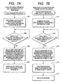
- Fig.7A shows a stationary picture processing on the side of the image recording apparatus 16, the packet for the stationary picture transmitted from the processor apparatus 12 is input by way of the network I/F 57, when the packet transmission is finished, the image data coupled with the spectroscopic characteristic information is written to be held by the hard disk 61 by way of RAM 65 (step 201). Further, when at a keyboard or the like of the image recording apparatus 16, the wavelength is selected and the spectral image is operated to be displayed (step 202), the spectroscopic characteristic information held in the hard disk 61 is referred, the matrix data (coefficient set) in correspondence of the spectroscopic characteristic information of the scope 10, the light source 14 and the like is selected to be read from the plurality of matrix data of ROM 64 (step 203). Thereafter, at the spectral image-forming circuit 34B, the spectral image based on the matrix data is formed and the spectral image (stationary picture) is output to be displayed on the monitor 15 by way of the D/A converter 68 (step 204).
- Fig.7B shows a dynamic picture processing on the side of the image recording apparatus 16, when the spectroscopic characteristic information is received by way of the serial I/F 58, the spectroscopic characteristic information is transferred to RAM 65 and is primarily stored to be held thereby (step 211).
- the wavelength is selected and the spectral image is operated to display (step 212), based on the spectroscopic characteristic information, the corresponding matrix data (coefficient set) is selected to be read from the plurality of matrix data of the ROM 64 (step 213), similar to the case of the static picture, at the spectral image-forming circuit 34B, the spectral image based on the matrix data is formed (step 214), and the spectral image (dynamic picture) is output to be displayed on the monitor 15 by way of the D/A converter 68 (step 215).
- the spectral image is formed (generated) by selecting the wavelength regions of ⁇ 1, ⁇ 2, ⁇ 3 signals by operating the keyboard or the like of the image recording apparatus 16, first, the Y/C (chrominance) signal constituting the image signal stored to the hard disk 61 (in the case of the dynamic picture, output from the video grabber 59) is converted into the RGB signals by the first color converting circuit 70, thereafter, supplied to the color space conversion processing circuit 71 and at the color space conversion processing circuit 71, by the RGB signal data and the matrix data, the matrix operation of Equation 1 is carried out for forming the spectral image.
- the Y/C (chrominance) signal constituting the image signal stored to the hard disk 61 (in the case of the dynamic picture, output from the video grabber 59) is converted into the RGB signals by the first color converting circuit 70, thereafter, supplied to the color space conversion processing circuit 71 and at the color space conversion processing circuit 71, by the RGB signal data and the matrix data, the matrix operation of Equation 1 is carried out for forming the
- the signals of ⁇ 1, ⁇ 2, ⁇ 3 are supplied to the amplifying circuit 73, further, when the single color mode is selected, any signal of ⁇ 1, ⁇ 2, ⁇ 3 is supplied thereto, amplified by the respective gains e 1 , e 2 , e 3 to provide e 1 ⁇ 1, e 2 ⁇ 2 , e 3 ⁇ 3 .
- the signals of ⁇ 1, ⁇ 2, ⁇ 3 as the Rs, Gs, Bs signals are converted into the Y/C signal (Y, Rs-Y, Bs-Y), and by supplying the Y/C signal to the monitor 15 by way of the D/A converter 68 (3 5), the spectral image is displayed on the monitor 15.
- the spectral image displayed on the monitor 15 is constituted by color components of the wavelength regions shown in Fig.8 and Fig.9. That is, Fig.8 is a conceptual diagram overlapping the three wavelength regions forming the spectral image on the reflection spector of the organism, further, Fig.9 is a conceptual diagram overlapping the three wavelength regions on the spectroscopic sensitivity characteristic of CCD 18 of the primary color type (graduations of the color filters and the wavelength regions of the ⁇ 1, ⁇ 2, ⁇ 3 signals do not coincide with each other), according to the embodiment, as illustrated, the wavelengths p21, p45, p51 selected as ⁇ 1, ⁇ 2, ⁇ 3 signals are the color signals of the wavelength regions successively constituting the center wavelengths by 500nm, 620nm, 650nm in a range of about ⁇ 10nm, and the spectral image (dynamic picture and stationary picture) constituted by combining colors of the three wavelength regions is displayed.
- the spectral image provided by the image recording apparatus 16 can maintain the reproducibility in the same wavelength regions even when the color image provided by the scope 10 and the light source 14 kinds of which differ is held. That is, the excellent spectral image in which the reproducibility is not dispersed is provided when in the scope 10, the spectroscopic characteristic of CCD 18, the spectroscopic characteristic in consideration of the object optical system, the light guide or the like differ and even when at the light source apparatus 14, the spectroscopic characteristic differs by the difference of whether the light source lamp 50 is the Xenon lamp or the halogen lamp, or by the difference of the diaphragm position of the diaphragm 49, as mentioned later.
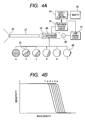
- Figs.4A and 4B shows the spectroscopic characteristic which is changed by the constitution of the light source 14 and the diaphragm position of an illuminating light (illuminating light amount), according to the embodiment, as shown by Fig.4A, 6 stages of positions from, for example, a diaphragm position a of full open to diaphragm position f near to full close are detected by the diaphragm position detecting sensor 52, and data of the diaphragm positions a through f is supplied to the image recording apparatus 16 by the fourth microcomputer 54 by way of the third microcomputer 43. Further, at the image recording apparatus 16, the matrix data in correspondence with the diaphragm positions a through f is selected, thereby, the matrix operation is carried out for forming the spectral image.
- Fig.4B shows the spectroscopic characteristic at the position of the diaphragm (blade) 49, according to the diaphragm 49 of the embodiment, the more narrowed from the full open diaphragm position f to the diaphragm position f, the more the spectroscopic characteristic in which the red region component is gradually cut from the side of the long wavelength (a ⁇ f) is constituted.
- the matrix data in correspondence with the diaphragm positions a through f is stored to ROM 64 of the image recording apparatus 16, for example, when the current diaphragm position is c, the matrix data (coefficient set) in correspondence with the diaphragm position c is read from ROM 64 and the operation by the matrix data is carried out.
- the matrix data (coefficient set) in correspondence with the diaphragm position c is read from ROM 64 and the operation by the matrix data is carried out.
- the spectral image-forming circuit 34A is provided even at the processor apparatus 12, by selecting the wavelength regions of ⁇ 1, ⁇ 2, ⁇ 3 signals by operating the operation panel or the like from the processor apparatus 12, in carrying out observation, treatment by the scope 10, the spectral image can also be formed to be displayed on the monitor 15.
Landscapes
- Health & Medical Sciences (AREA)
- Life Sciences & Earth Sciences (AREA)
- Engineering & Computer Science (AREA)
- Surgery (AREA)
- Signal Processing (AREA)
- Physics & Mathematics (AREA)
- Multimedia (AREA)
- Molecular Biology (AREA)
- General Health & Medical Sciences (AREA)
- Pathology (AREA)
- Veterinary Medicine (AREA)
- Public Health (AREA)
- Biomedical Technology (AREA)
- Heart & Thoracic Surgery (AREA)
- Medical Informatics (AREA)
- Biophysics (AREA)
- Animal Behavior & Ethology (AREA)
- Optics & Photonics (AREA)
- Nuclear Medicine, Radiotherapy & Molecular Imaging (AREA)
- Radiology & Medical Imaging (AREA)
- Spectroscopy & Molecular Physics (AREA)
- Endoscopes (AREA)
Applications Claiming Priority (1)
| Application Number | Priority Date | Filing Date | Title |
|---|---|---|---|
| JP2005080426A JP4741264B2 (ja) | 2005-03-18 | 2005-03-18 | 内視鏡分光画像システム装置 |
Publications (2)
| Publication Number | Publication Date |
|---|---|
| EP1702556A1 true EP1702556A1 (fr) | 2006-09-20 |
| EP1702556B1 EP1702556B1 (fr) | 2013-05-29 |
Family
ID=36646138
Family Applications (1)
| Application Number | Title | Priority Date | Filing Date |
|---|---|---|---|
| EP06005419.4A Expired - Lifetime EP1702556B1 (fr) | 2005-03-18 | 2006-03-16 | Endoscope et dispositif de traitement d'images spectrales |
Country Status (3)
| Country | Link |
|---|---|
| US (1) | US8040373B2 (fr) |
| EP (1) | EP1702556B1 (fr) |
| JP (1) | JP4741264B2 (fr) |
Cited By (3)
| Publication number | Priority date | Publication date | Assignee | Title |
|---|---|---|---|---|
| EP1813186A1 (fr) * | 2006-01-27 | 2007-08-01 | Fujinon Corporation | Système endoscopique |
| CN102740757A (zh) * | 2010-02-05 | 2012-10-17 | 奥林巴斯株式会社 | 图像处理装置、内窥镜系统、程序以及图像处理方法 |
| US9589103B2 (en) | 2010-11-15 | 2017-03-07 | Fujifilm Corporation | Medical image recording/reproducing apparatus, medical image recording/reproducing method and computer readable medium |
Families Citing this family (21)
| Publication number | Priority date | Publication date | Assignee | Title |
|---|---|---|---|---|
| JP4868976B2 (ja) * | 2006-08-18 | 2012-02-01 | オリンパスメディカルシステムズ株式会社 | 内視鏡装置 |
| JP2009225830A (ja) * | 2008-03-19 | 2009-10-08 | Fujifilm Corp | 電子内視鏡装置 |
| JP4981730B2 (ja) * | 2008-03-26 | 2012-07-25 | 国立大学法人東京工業大学 | 分光画像生成装置及び分光画像生成方法 |
| JP5235473B2 (ja) * | 2008-04-04 | 2013-07-10 | Hoya株式会社 | 分光特性推定装置 |
| DE102009008834A1 (de) | 2008-08-02 | 2010-02-18 | Dr. Hein & Partner GbR (vertretungsberechtigter Gesellschafter Dr. Achim Hein, 90599 Dietenhofen) | Vorrichtung und Verfahren zur elektronischen Erfassung und Auswertung von medizinischen Daten |
| JP2010043979A (ja) * | 2008-08-13 | 2010-02-25 | Yuichi Kamata | 分光画像計測装置 |
| JP5802364B2 (ja) | 2009-11-13 | 2015-10-28 | オリンパス株式会社 | 画像処理装置、電子機器、内視鏡システム及びプログラム |
| JP5658873B2 (ja) | 2009-11-13 | 2015-01-28 | オリンパス株式会社 | 画像処理装置、電子機器、内視鏡システム及びプログラム |
| JP2011194082A (ja) * | 2010-03-19 | 2011-10-06 | Fujifilm Corp | 内視鏡画像補正装置および内視鏡装置 |
| JP5604248B2 (ja) * | 2010-09-28 | 2014-10-08 | 富士フイルム株式会社 | 内視鏡画像表示装置 |
| JP5256270B2 (ja) * | 2010-11-15 | 2013-08-07 | 富士フイルム株式会社 | 医療用画像再生装置及び医療用画像再生方法並びにプログラム |
| JP5346907B2 (ja) * | 2010-11-15 | 2013-11-20 | 富士フイルム株式会社 | 医療用画像記録再生装置、及びプログラム |
| JP5766958B2 (ja) * | 2011-01-21 | 2015-08-19 | オリンパス株式会社 | 顕微鏡システム、情報処理装置、及び情報処理プログラム |
| CN103220962B (zh) * | 2011-01-31 | 2015-03-25 | 奥林巴斯医疗株式会社 | 光源装置 |
| WO2013101912A1 (fr) | 2011-12-29 | 2013-07-04 | Cook Medical Technoloies Llc | Cathéter de visualisation à espace optimisé ayant un dispositif de maintien de train de caméra |
| US9668643B2 (en) | 2011-12-29 | 2017-06-06 | Cook Medical Technologies Llc | Space-optimized visualization catheter with oblong shape |
| EP3150106B1 (fr) | 2011-12-29 | 2024-03-27 | Cook Medical Technologies LLC | Cathéter de visualisation d'espace optimisé avec un support de chariot de caméra dans un cathéter avec lumière désaxée |
| JP6097629B2 (ja) * | 2013-04-26 | 2017-03-15 | Hoya株式会社 | 病変評価情報生成装置 |
| WO2016035401A1 (fr) * | 2014-09-03 | 2016-03-10 | オリンパス株式会社 | Dispositif formant endoscope |
| CN115245312B (zh) * | 2021-04-27 | 2025-04-11 | 山东威高宏瑞医学科技有限公司 | 内窥镜多光谱图像处理系统及处理和训练方法 |
| US20240231072A9 (en) * | 2022-10-21 | 2024-07-11 | Karl Storz Imaging, Inc. | Imaging Device Including Two Image Sensors Enabling Multiple Imaging Modes and Associated Imaging Systems |
Citations (7)
| Publication number | Priority date | Publication date | Assignee | Title |
|---|---|---|---|---|
| US4885634A (en) | 1987-10-27 | 1989-12-05 | Olympus Optical Co., Ltd. | Endoscope apparatus capable of monochrome display with respect to specific wavelength regions in the visible region |
| US4926247A (en) * | 1986-10-15 | 1990-05-15 | Olympus Optical Co., Ltd. | Color imaging apparatus including a means for electronically non-linearly expanding and compressing dynamic range of an image signal |
| US5331551A (en) * | 1989-10-02 | 1994-07-19 | Olympus Optical Co., Ltd. | Endoscope image recording system for compressing and recording endoscope image data |
| US5408263A (en) * | 1992-06-16 | 1995-04-18 | Olympus Optical Co., Ltd. | Electronic endoscope apparatus |
| US20030001952A1 (en) * | 2001-06-15 | 2003-01-02 | Asahi Kogaku Kogyo Kabushiki Kaisha | Electronic endoscope with color adjustment function |
| JP2003093336A (ja) | 2001-09-26 | 2003-04-02 | Toshiba Corp | 電子内視鏡装置 |
| US20040141054A1 (en) | 1999-06-09 | 2004-07-22 | Olympus Corporation | Image processing unit whose ability to process endoscopic image signal can be expanded, and endoscopic imaging system |
Family Cites Families (18)
| Publication number | Priority date | Publication date | Assignee | Title |
|---|---|---|---|---|
| JP2643948B2 (ja) * | 1987-08-10 | 1997-08-25 | オリンパス光学工業株式会社 | 電子内視鏡装置 |
| JPS6417621A (en) * | 1987-07-13 | 1989-01-20 | Toshiba Corp | Electronic endoscopic apparatus |
| JP2996373B2 (ja) * | 1992-06-16 | 1999-12-27 | オリンパス光学工業株式会社 | 電子内視鏡装置 |
| JPH06335449A (ja) * | 1993-05-31 | 1994-12-06 | Olympus Optical Co Ltd | 電子内視鏡装置 |
| JP2000014629A (ja) * | 1998-07-02 | 2000-01-18 | Olympus Optical Co Ltd | 内視鏡分光装置 |
| JP2000221417A (ja) * | 1999-02-04 | 2000-08-11 | Olympus Optical Co Ltd | 内視鏡撮像装置 |
| JP2000350231A (ja) * | 1999-06-02 | 2000-12-15 | Olympus Optical Co Ltd | 映像信号処理装置 |
| JP2001112712A (ja) * | 1999-10-18 | 2001-04-24 | Olympus Optical Co Ltd | 内視鏡撮像装置 |
| DE10015816A1 (de) * | 2000-03-30 | 2001-10-18 | Infineon Technologies Ag | Biosensorchip |
| JP4502577B2 (ja) * | 2002-12-19 | 2010-07-14 | Hoya株式会社 | 電子内視鏡装置 |
| US20040225222A1 (en) * | 2003-05-08 | 2004-11-11 | Haishan Zeng | Real-time contemporaneous multimodal imaging and spectroscopy uses thereof |
| JP2005006856A (ja) * | 2003-06-18 | 2005-01-13 | Olympus Corp | 内視鏡装置 |
| JP4343594B2 (ja) * | 2003-06-23 | 2009-10-14 | オリンパス株式会社 | 内視鏡装置 |
| JP4647347B2 (ja) * | 2005-03-04 | 2011-03-09 | 富士フイルム株式会社 | 内視鏡装置 |
| JP4732769B2 (ja) * | 2005-03-04 | 2011-07-27 | 富士フイルム株式会社 | 内視鏡装置 |
| JP4647346B2 (ja) * | 2005-03-04 | 2011-03-09 | 富士フイルム株式会社 | 内視鏡装置 |
| EP1698272B1 (fr) * | 2005-03-04 | 2012-12-05 | FUJIFILM Corporation | Endoscope et dispositif de traitement d'images |
| JP4637620B2 (ja) * | 2005-03-18 | 2011-02-23 | 富士フイルム株式会社 | 内視鏡システム装置 |
-
2005
- 2005-03-18 JP JP2005080426A patent/JP4741264B2/ja not_active Expired - Lifetime
-
2006
- 2006-03-16 EP EP06005419.4A patent/EP1702556B1/fr not_active Expired - Lifetime
- 2006-03-17 US US11/377,272 patent/US8040373B2/en not_active Expired - Fee Related
Patent Citations (7)
| Publication number | Priority date | Publication date | Assignee | Title |
|---|---|---|---|---|
| US4926247A (en) * | 1986-10-15 | 1990-05-15 | Olympus Optical Co., Ltd. | Color imaging apparatus including a means for electronically non-linearly expanding and compressing dynamic range of an image signal |
| US4885634A (en) | 1987-10-27 | 1989-12-05 | Olympus Optical Co., Ltd. | Endoscope apparatus capable of monochrome display with respect to specific wavelength regions in the visible region |
| US5331551A (en) * | 1989-10-02 | 1994-07-19 | Olympus Optical Co., Ltd. | Endoscope image recording system for compressing and recording endoscope image data |
| US5408263A (en) * | 1992-06-16 | 1995-04-18 | Olympus Optical Co., Ltd. | Electronic endoscope apparatus |
| US20040141054A1 (en) | 1999-06-09 | 2004-07-22 | Olympus Corporation | Image processing unit whose ability to process endoscopic image signal can be expanded, and endoscopic imaging system |
| US20030001952A1 (en) * | 2001-06-15 | 2003-01-02 | Asahi Kogaku Kogyo Kabushiki Kaisha | Electronic endoscope with color adjustment function |
| JP2003093336A (ja) | 2001-09-26 | 2003-04-02 | Toshiba Corp | 電子内視鏡装置 |
Cited By (6)
| Publication number | Priority date | Publication date | Assignee | Title |
|---|---|---|---|---|
| EP1813186A1 (fr) * | 2006-01-27 | 2007-08-01 | Fujinon Corporation | Système endoscopique |
| US7965878B2 (en) | 2006-01-27 | 2011-06-21 | Fujinon Corporation | Endoscopic system with spectral image forming circuit |
| CN102740757A (zh) * | 2010-02-05 | 2012-10-17 | 奥林巴斯株式会社 | 图像处理装置、内窥镜系统、程序以及图像处理方法 |
| CN102740757B (zh) * | 2010-02-05 | 2016-02-10 | 奥林巴斯株式会社 | 图像处理装置、内窥镜系统以及图像处理方法 |
| US9589103B2 (en) | 2010-11-15 | 2017-03-07 | Fujifilm Corporation | Medical image recording/reproducing apparatus, medical image recording/reproducing method and computer readable medium |
| EP2453376B1 (fr) * | 2010-11-15 | 2019-02-20 | Fujifilm Corporation | Appareil de reproduction/enregistrement d'images médicales, procédé de reproduction/enregistrement d'images médicales et programme |
Also Published As
| Publication number | Publication date |
|---|---|
| US8040373B2 (en) | 2011-10-18 |
| JP4741264B2 (ja) | 2011-08-03 |
| US20060252988A1 (en) | 2006-11-09 |
| JP2006255324A (ja) | 2006-09-28 |
| EP1702556B1 (fr) | 2013-05-29 |
Similar Documents
| Publication | Publication Date | Title |
|---|---|---|
| EP1702556B1 (fr) | Endoscope et dispositif de traitement d'images spectrales | |
| JP4732769B2 (ja) | 内視鏡装置 | |
| JP4647347B2 (ja) | 内視鏡装置 | |
| US8125514B2 (en) | Electronic endoscope apparatus | |
| EP1702557B1 (fr) | Endoscope et dispositif de traitement d'images | |
| JP4647346B2 (ja) | 内視鏡装置 | |
| EP2123213B1 (fr) | Procédé et appareil pour obtenir une image fluorescente, endoscope à fluorescence, et unité d'excitation lumineuse | |
| US8633977B2 (en) | Electronic endoscope apparatus | |
| EP1813186B1 (fr) | Système endoscopique | |
| JP2006239206A (ja) | 内視鏡装置 | |
| EP1774897B1 (fr) | Appareil d'endoscopie | |
| EP2105086B1 (fr) | Appareil d'endoscope électronique |
Legal Events
| Date | Code | Title | Description |
|---|---|---|---|
| PUAI | Public reference made under article 153(3) epc to a published international application that has entered the european phase |
Free format text: ORIGINAL CODE: 0009012 |
|
| 17P | Request for examination filed |
Effective date: 20060316 |
|
| AK | Designated contracting states |
Kind code of ref document: A1 Designated state(s): AT BE BG CH CY CZ DE DK EE ES FI FR GB GR HU IE IS IT LI LT LU LV MC NL PL PT RO SE SI SK TR |
|
| AX | Request for extension of the european patent |
Extension state: AL BA HR MK YU |
|
| AKX | Designation fees paid |
Designated state(s): AT BE BG CH CY CZ DE DK EE ES FI FR GB GR HU IE IS IT LI LT LU LV MC NL PL PT RO SE SI SK TR |
|
| 17Q | First examination report despatched |
Effective date: 20101119 |
|
| RAP1 | Party data changed (applicant data changed or rights of an application transferred) |
Owner name: FUJIFILM CORPORATION |
|
| GRAC | Information related to communication of intention to grant a patent modified |
Free format text: ORIGINAL CODE: EPIDOSCIGR1 |
|
| GRAP | Despatch of communication of intention to grant a patent |
Free format text: ORIGINAL CODE: EPIDOSNIGR1 |
|
| GRAS | Grant fee paid |
Free format text: ORIGINAL CODE: EPIDOSNIGR3 |
|
| REG | Reference to a national code |
Ref country code: DE Ref legal event code: R079 Ref document number: 602006036522 Country of ref document: DE Free format text: PREVIOUS MAIN CLASS: A61B0001045000 Ipc: A61B0005000000 |
|
| GRAP | Despatch of communication of intention to grant a patent |
Free format text: ORIGINAL CODE: EPIDOSNIGR1 |
|
| RIC1 | Information provided on ipc code assigned before grant |
Ipc: H04N 9/07 20060101ALI20130205BHEP Ipc: A61B 1/045 20060101ALI20130205BHEP Ipc: H04N 1/64 20060101ALI20130205BHEP Ipc: A61B 1/00 20060101ALI20130205BHEP Ipc: H04N 5/235 20060101ALI20130205BHEP Ipc: H04N 9/67 20060101ALI20130205BHEP Ipc: A61B 1/05 20060101ALI20130205BHEP Ipc: A61B 5/00 20060101AFI20130205BHEP |
|
| GRAA | (expected) grant |
Free format text: ORIGINAL CODE: 0009210 |
|
| AK | Designated contracting states |
Kind code of ref document: B1 Designated state(s): AT BE BG CH CY CZ DE DK EE ES FI FR GB GR HU IE IS IT LI LT LU LV MC NL PL PT RO SE SI SK TR |
|
| REG | Reference to a national code |
Ref country code: GB Ref legal event code: FG4D |
|
| REG | Reference to a national code |
Ref country code: CH Ref legal event code: EP |
|
| REG | Reference to a national code |
Ref country code: AT Ref legal event code: REF Ref document number: 613855 Country of ref document: AT Kind code of ref document: T Effective date: 20130615 |
|
| REG | Reference to a national code |
Ref country code: IE Ref legal event code: FG4D |
|
| REG | Reference to a national code |
Ref country code: DE Ref legal event code: R096 Ref document number: 602006036522 Country of ref document: DE Effective date: 20130725 |
|
| REG | Reference to a national code |
Ref country code: AT Ref legal event code: MK05 Ref document number: 613855 Country of ref document: AT Kind code of ref document: T Effective date: 20130529 |
|
| REG | Reference to a national code |
Ref country code: LT Ref legal event code: MG4D |
|
| PG25 | Lapsed in a contracting state [announced via postgrant information from national office to epo] |
Ref country code: LT Free format text: LAPSE BECAUSE OF FAILURE TO SUBMIT A TRANSLATION OF THE DESCRIPTION OR TO PAY THE FEE WITHIN THE PRESCRIBED TIME-LIMIT Effective date: 20130529 Ref country code: AT Free format text: LAPSE BECAUSE OF FAILURE TO SUBMIT A TRANSLATION OF THE DESCRIPTION OR TO PAY THE FEE WITHIN THE PRESCRIBED TIME-LIMIT Effective date: 20130529 Ref country code: GR Free format text: LAPSE BECAUSE OF FAILURE TO SUBMIT A TRANSLATION OF THE DESCRIPTION OR TO PAY THE FEE WITHIN THE PRESCRIBED TIME-LIMIT Effective date: 20130830 Ref country code: SI Free format text: LAPSE BECAUSE OF FAILURE TO SUBMIT A TRANSLATION OF THE DESCRIPTION OR TO PAY THE FEE WITHIN THE PRESCRIBED TIME-LIMIT Effective date: 20130529 Ref country code: IS Free format text: LAPSE BECAUSE OF FAILURE TO SUBMIT A TRANSLATION OF THE DESCRIPTION OR TO PAY THE FEE WITHIN THE PRESCRIBED TIME-LIMIT Effective date: 20130929 Ref country code: SE Free format text: LAPSE BECAUSE OF FAILURE TO SUBMIT A TRANSLATION OF THE DESCRIPTION OR TO PAY THE FEE WITHIN THE PRESCRIBED TIME-LIMIT Effective date: 20130529 Ref country code: FI Free format text: LAPSE BECAUSE OF FAILURE TO SUBMIT A TRANSLATION OF THE DESCRIPTION OR TO PAY THE FEE WITHIN THE PRESCRIBED TIME-LIMIT Effective date: 20130529 Ref country code: ES Free format text: LAPSE BECAUSE OF FAILURE TO SUBMIT A TRANSLATION OF THE DESCRIPTION OR TO PAY THE FEE WITHIN THE PRESCRIBED TIME-LIMIT Effective date: 20130909 Ref country code: PT Free format text: LAPSE BECAUSE OF FAILURE TO SUBMIT A TRANSLATION OF THE DESCRIPTION OR TO PAY THE FEE WITHIN THE PRESCRIBED TIME-LIMIT Effective date: 20130930 |
|
| REG | Reference to a national code |
Ref country code: NL Ref legal event code: VDEP Effective date: 20130529 |
|
| PG25 | Lapsed in a contracting state [announced via postgrant information from national office to epo] |
Ref country code: PL Free format text: LAPSE BECAUSE OF FAILURE TO SUBMIT A TRANSLATION OF THE DESCRIPTION OR TO PAY THE FEE WITHIN THE PRESCRIBED TIME-LIMIT Effective date: 20130529 Ref country code: BG Free format text: LAPSE BECAUSE OF FAILURE TO SUBMIT A TRANSLATION OF THE DESCRIPTION OR TO PAY THE FEE WITHIN THE PRESCRIBED TIME-LIMIT Effective date: 20130829 |
|
| PG25 | Lapsed in a contracting state [announced via postgrant information from national office to epo] |
Ref country code: LV Free format text: LAPSE BECAUSE OF FAILURE TO SUBMIT A TRANSLATION OF THE DESCRIPTION OR TO PAY THE FEE WITHIN THE PRESCRIBED TIME-LIMIT Effective date: 20130529 |
|
| PG25 | Lapsed in a contracting state [announced via postgrant information from national office to epo] |
Ref country code: DK Free format text: LAPSE BECAUSE OF FAILURE TO SUBMIT A TRANSLATION OF THE DESCRIPTION OR TO PAY THE FEE WITHIN THE PRESCRIBED TIME-LIMIT Effective date: 20130529 Ref country code: BE Free format text: LAPSE BECAUSE OF FAILURE TO SUBMIT A TRANSLATION OF THE DESCRIPTION OR TO PAY THE FEE WITHIN THE PRESCRIBED TIME-LIMIT Effective date: 20130529 Ref country code: SK Free format text: LAPSE BECAUSE OF FAILURE TO SUBMIT A TRANSLATION OF THE DESCRIPTION OR TO PAY THE FEE WITHIN THE PRESCRIBED TIME-LIMIT Effective date: 20130529 Ref country code: CZ Free format text: LAPSE BECAUSE OF FAILURE TO SUBMIT A TRANSLATION OF THE DESCRIPTION OR TO PAY THE FEE WITHIN THE PRESCRIBED TIME-LIMIT Effective date: 20130529 Ref country code: EE Free format text: LAPSE BECAUSE OF FAILURE TO SUBMIT A TRANSLATION OF THE DESCRIPTION OR TO PAY THE FEE WITHIN THE PRESCRIBED TIME-LIMIT Effective date: 20130529 |
|
| PG25 | Lapsed in a contracting state [announced via postgrant information from national office to epo] |
Ref country code: RO Free format text: LAPSE BECAUSE OF FAILURE TO SUBMIT A TRANSLATION OF THE DESCRIPTION OR TO PAY THE FEE WITHIN THE PRESCRIBED TIME-LIMIT Effective date: 20130529 Ref country code: NL Free format text: LAPSE BECAUSE OF FAILURE TO SUBMIT A TRANSLATION OF THE DESCRIPTION OR TO PAY THE FEE WITHIN THE PRESCRIBED TIME-LIMIT Effective date: 20130529 Ref country code: IT Free format text: LAPSE BECAUSE OF FAILURE TO SUBMIT A TRANSLATION OF THE DESCRIPTION OR TO PAY THE FEE WITHIN THE PRESCRIBED TIME-LIMIT Effective date: 20130529 |
|
| PLBE | No opposition filed within time limit |
Free format text: ORIGINAL CODE: 0009261 |
|
| STAA | Information on the status of an ep patent application or granted ep patent |
Free format text: STATUS: NO OPPOSITION FILED WITHIN TIME LIMIT |
|
| 26N | No opposition filed |
Effective date: 20140303 |
|
| REG | Reference to a national code |
Ref country code: DE Ref legal event code: R097 Ref document number: 602006036522 Country of ref document: DE Effective date: 20140303 |
|
| PG25 | Lapsed in a contracting state [announced via postgrant information from national office to epo] |
Ref country code: LU Free format text: LAPSE BECAUSE OF FAILURE TO SUBMIT A TRANSLATION OF THE DESCRIPTION OR TO PAY THE FEE WITHIN THE PRESCRIBED TIME-LIMIT Effective date: 20140316 |
|
| REG | Reference to a national code |
Ref country code: CH Ref legal event code: PL |
|
| REG | Reference to a national code |
Ref country code: IE Ref legal event code: MM4A |
|
| PG25 | Lapsed in a contracting state [announced via postgrant information from national office to epo] |
Ref country code: IE Free format text: LAPSE BECAUSE OF NON-PAYMENT OF DUE FEES Effective date: 20140316 Ref country code: CH Free format text: LAPSE BECAUSE OF NON-PAYMENT OF DUE FEES Effective date: 20140331 Ref country code: LI Free format text: LAPSE BECAUSE OF NON-PAYMENT OF DUE FEES Effective date: 20140331 |
|
| REG | Reference to a national code |
Ref country code: FR Ref legal event code: PLFP Year of fee payment: 10 |
|
| PGFP | Annual fee paid to national office [announced via postgrant information from national office to epo] |
Ref country code: FR Payment date: 20150309 Year of fee payment: 10 Ref country code: GB Payment date: 20150311 Year of fee payment: 10 |
|
| PG25 | Lapsed in a contracting state [announced via postgrant information from national office to epo] |
Ref country code: MC Free format text: LAPSE BECAUSE OF FAILURE TO SUBMIT A TRANSLATION OF THE DESCRIPTION OR TO PAY THE FEE WITHIN THE PRESCRIBED TIME-LIMIT Effective date: 20130529 |
|
| PG25 | Lapsed in a contracting state [announced via postgrant information from national office to epo] |
Ref country code: CY Free format text: LAPSE BECAUSE OF FAILURE TO SUBMIT A TRANSLATION OF THE DESCRIPTION OR TO PAY THE FEE WITHIN THE PRESCRIBED TIME-LIMIT Effective date: 20130529 |
|
| PG25 | Lapsed in a contracting state [announced via postgrant information from national office to epo] |
Ref country code: HU Free format text: LAPSE BECAUSE OF FAILURE TO SUBMIT A TRANSLATION OF THE DESCRIPTION OR TO PAY THE FEE WITHIN THE PRESCRIBED TIME-LIMIT; INVALID AB INITIO Effective date: 20060316 Ref country code: TR Free format text: LAPSE BECAUSE OF FAILURE TO SUBMIT A TRANSLATION OF THE DESCRIPTION OR TO PAY THE FEE WITHIN THE PRESCRIBED TIME-LIMIT Effective date: 20130529 |
|
| GBPC | Gb: european patent ceased through non-payment of renewal fee |
Effective date: 20160316 |
|
| REG | Reference to a national code |
Ref country code: FR Ref legal event code: ST Effective date: 20161130 |
|
| PG25 | Lapsed in a contracting state [announced via postgrant information from national office to epo] |
Ref country code: FR Free format text: LAPSE BECAUSE OF NON-PAYMENT OF DUE FEES Effective date: 20160331 Ref country code: GB Free format text: LAPSE BECAUSE OF NON-PAYMENT OF DUE FEES Effective date: 20160316 |
|
| REG | Reference to a national code |
Ref country code: DE Ref legal event code: R082 Ref document number: 602006036522 Country of ref document: DE Representative=s name: KLUNKER IP PATENTANWAELTE PARTG MBB, DE |
|
| PGFP | Annual fee paid to national office [announced via postgrant information from national office to epo] |
Ref country code: DE Payment date: 20190305 Year of fee payment: 14 |
|
| REG | Reference to a national code |
Ref country code: DE Ref legal event code: R119 Ref document number: 602006036522 Country of ref document: DE |
|
| PG25 | Lapsed in a contracting state [announced via postgrant information from national office to epo] |
Ref country code: DE Free format text: LAPSE BECAUSE OF NON-PAYMENT OF DUE FEES Effective date: 20201001 |