EP1702823B1 - Système de freinage avec des freins primaires et secondaires - Google Patents
Système de freinage avec des freins primaires et secondaires Download PDFInfo
- Publication number
- EP1702823B1 EP1702823B1 EP06110988A EP06110988A EP1702823B1 EP 1702823 B1 EP1702823 B1 EP 1702823B1 EP 06110988 A EP06110988 A EP 06110988A EP 06110988 A EP06110988 A EP 06110988A EP 1702823 B1 EP1702823 B1 EP 1702823B1
- Authority
- EP
- European Patent Office
- Prior art keywords
- brake
- piston
- primary
- plate
- brake piston
- Prior art date
- Legal status (The legal status is an assumption and is not a legal conclusion. Google has not performed a legal analysis and makes no representation as to the accuracy of the status listed.)
- Expired - Lifetime
Links
Images


Classifications
-
- B—PERFORMING OPERATIONS; TRANSPORTING
- B60—VEHICLES IN GENERAL
- B60T—VEHICLE BRAKE CONTROL SYSTEMS OR PARTS THEREOF; BRAKE CONTROL SYSTEMS OR PARTS THEREOF, IN GENERAL; ARRANGEMENT OF BRAKING ELEMENTS ON VEHICLES IN GENERAL; PORTABLE DEVICES FOR PREVENTING UNWANTED MOVEMENT OF VEHICLES; VEHICLE MODIFICATIONS TO FACILITATE COOLING OF BRAKES
- B60T13/00—Transmitting braking action from initiating means to ultimate brake actuator with power assistance or drive; Brake systems incorporating such transmitting means, e.g. air-pressure brake systems
- B60T13/10—Transmitting braking action from initiating means to ultimate brake actuator with power assistance or drive; Brake systems incorporating such transmitting means, e.g. air-pressure brake systems with fluid assistance, drive, or release
- B60T13/12—Transmitting braking action from initiating means to ultimate brake actuator with power assistance or drive; Brake systems incorporating such transmitting means, e.g. air-pressure brake systems with fluid assistance, drive, or release the fluid being liquid
- B60T13/16—Transmitting braking action from initiating means to ultimate brake actuator with power assistance or drive; Brake systems incorporating such transmitting means, e.g. air-pressure brake systems with fluid assistance, drive, or release the fluid being liquid using pumps directly, i.e. without interposition of accumulators or reservoirs
-
- F—MECHANICAL ENGINEERING; LIGHTING; HEATING; WEAPONS; BLASTING
- F16—ENGINEERING ELEMENTS AND UNITS; GENERAL MEASURES FOR PRODUCING AND MAINTAINING EFFECTIVE FUNCTIONING OF MACHINES OR INSTALLATIONS; THERMAL INSULATION IN GENERAL
- F16D—COUPLINGS FOR TRANSMITTING ROTATION; CLUTCHES; BRAKES
- F16D65/00—Parts or details
- F16D65/14—Actuating mechanisms for brakes; Means for initiating operation at a predetermined position
- F16D65/16—Actuating mechanisms for brakes; Means for initiating operation at a predetermined position arranged in or on the brake
- F16D65/18—Actuating mechanisms for brakes; Means for initiating operation at a predetermined position arranged in or on the brake adapted for drawing members together, e.g. for disc brakes
- F16D65/186—Actuating mechanisms for brakes; Means for initiating operation at a predetermined position arranged in or on the brake adapted for drawing members together, e.g. for disc brakes with full-face force-applying member, e.g. annular
-
- F—MECHANICAL ENGINEERING; LIGHTING; HEATING; WEAPONS; BLASTING
- F16—ENGINEERING ELEMENTS AND UNITS; GENERAL MEASURES FOR PRODUCING AND MAINTAINING EFFECTIVE FUNCTIONING OF MACHINES OR INSTALLATIONS; THERMAL INSULATION IN GENERAL
- F16D—COUPLINGS FOR TRANSMITTING ROTATION; CLUTCHES; BRAKES
- F16D2121/00—Type of actuator operation force
- F16D2121/02—Fluid pressure
-
- F—MECHANICAL ENGINEERING; LIGHTING; HEATING; WEAPONS; BLASTING
- F16—ENGINEERING ELEMENTS AND UNITS; GENERAL MEASURES FOR PRODUCING AND MAINTAINING EFFECTIVE FUNCTIONING OF MACHINES OR INSTALLATIONS; THERMAL INSULATION IN GENERAL
- F16D—COUPLINGS FOR TRANSMITTING ROTATION; CLUTCHES; BRAKES
- F16D2123/00—Multiple operation forces
-
- F—MECHANICAL ENGINEERING; LIGHTING; HEATING; WEAPONS; BLASTING
- F16—ENGINEERING ELEMENTS AND UNITS; GENERAL MEASURES FOR PRODUCING AND MAINTAINING EFFECTIVE FUNCTIONING OF MACHINES OR INSTALLATIONS; THERMAL INSULATION IN GENERAL
- F16D—COUPLINGS FOR TRANSMITTING ROTATION; CLUTCHES; BRAKES
- F16D2125/00—Components of actuators
- F16D2125/02—Fluid-pressure mechanisms
- F16D2125/06—Pistons
Definitions
- the present invention relates to a brake system having primary and secondary brakes.
- a brake system having primary and secondary brakes.
- Such a system is for instance known from WO-A-95/11825 .
- tractors both primary and secondary brake systems to help stop the vehicle when the vehicle is traveling at a high speed.
- all tractors sold in Europe are required to have primary service brakes which operate in the rear axle and which are controlled by independent foot pedals.
- the foot pedals operate a brake valve which transmits pressurized fluid to brake pistons which clamp the brake disk between the piston and a reaction plate.
- a secondary brake system is normally located in the front axle and is actuated by a hand lever.
- the secondary brake system also includes a piston which clamps a brake rotor against a stationary reaction plate.
- such a secondary brake system will create frictional drag and power loss, even when the secondary brake is not being applied. Also, such a secondary brake system takes up limited space in the front axle assembly, and it is difficult to include in a front axle assembly a secondary brake which is large enough to handle the heat generated by application of the secondary brake.
- a secondary brake is provided which is not located in the front axle of the vehicle and/or which is located with the primary brake.
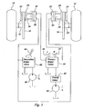
- Fig. 1 is a simplified schematic diagram of a brake system according to the present invention
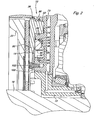
- Fig. 2 is a sectional view of a portion of a rear axle assembly incorporating the primary/secondary brakes of the present invention
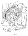
- Fig. 3 is a perspective view of a portion of the housing of the rear axle assembly of Fig. 2 ;
- Fig. 4 is perspective view of the primary brake piston of Fig. 2 ;
- Fig. 5 is perspective view of the secondary brake piston of Fig. 2 .
- left and right rear wheels 10 and 12 are connected to respective brake disks 14 and 16 by shafts 18 and 20.
- Non-rotating reaction plates 22 and 24 are positioned adjacent to the brake disks 14 and 16.
- Primary brake pistons 26 and 28 are movable in response to hydraulic pressure in primary brake piston chambers 30 and 32.
- Secondary brake pistons 34 and 36 are movable in response to hydraulic pressure in secondary brake piston chambers 38 and 40.
- Each secondary brake piston 34 and 36 is engagable with the corresponding primary brake piston 26 and 28.
- a portion of each primary brake piston 26 is positioned between the brake disk 14 and secondary piston 34.
- a portion of each primary brake piston 28 is positioned between brake disk 16 and secondary piston 36.
- the brake system includes a primary hydraulic pump 50 which supplies pressurized fluid via a priority valve 52 to a conventional primary brake valve 54 which is operated by left and right brake pedals 56 and 58.
- Primary brake valve 54 supplies controlled brake fluid pressure to left and right primary brake piston chambers 30 and 32.
- the brake system also includes a secondary hydraulic pump 60 which supplies pressurized fluid to a conventional secondary brake valve 62 which is preferably operated by a hand lever 64.
- Secondary brake valve 62 supplies controlled brake fluid pressure to left and right secondary brake piston chambers 38 and 40.
- FIG. 2 - 5 there is shown a portion of a rear axle assembly 70 which is symmetrical about a central rotation axis.
- the rear axle assembly 70 includes a brake disk or rotor 14 which rotates between reaction plate 22 and a rear axle housing which includes an inner housing portion 72 and an outer housing portion 73.
- housing portion 73 forms a radially outer annular groove 74 and a radially inner annular groove 76. Grooves 74 and 76 are separated by annular land 75.
- the primary brake piston 26 is annular and includes an annular plate 80 and an annular flange 82.
- Flange 82 is positioned near a radial outer edge of plate 80 and projects axially away from plate 80 and from brake disk 14 and into annular groove 74.
- Seals 84 and 86 are mounted in grooves in the radially inner and outer surfaces of annular groove 74.
- Flange 82 and groove 74 enclose primary brake piston chamber 30.
- a passage 83 in the housing portion 73 communicates chamber 30 with primary brake valve 54.
- the secondary brake piston 34 is annular and has an L-shaped cross sectional shape.
- Piston 34 is preferably positioned radially inwardly with respect to primary piston 26, and projects axially away from plate 80 and from brake disk 14 and into annular groove 76, which also has an L-shaped cross sectional shape.
- Seal 90 is mounted in a groove 91 in the radially inner surface of annular groove 76.
- Seal 92 is mounted in groove 93 in the radially outer surface of piston 34.
- Piston 34 and groove 76 enclose secondary brake piston chamber 38.
- a passage 77 in the housing portion 73 communicates chamber 38 with secondary brake valve 62.
- a plurality of blind bores 94 are formed in the secondary brake piston 34.
- the bores 94 open towards the brake disk 14.
- a spring 96 is mounted in each bore 94.
- An annular retainer plate 100 is bolted by a plurality of bolts 102 to a face of housing 73. The radially outer portion of plate 100 overlaps a radially inner portion of each bore 94 and overlaps a radially inner portion of the secondary brake piston 34.
- the plate 100 engages an end of each spring 96 and retains the springs 96 in the corresponding bores 94.
- the springs 96 are biased to urge the secondary brake piston 34 away from the brake disk 14. Fluid pressure in chamber 38 will urge the secondary brake piston 34 towards the brake disk 14.
Landscapes
- Engineering & Computer Science (AREA)
- General Engineering & Computer Science (AREA)
- Mechanical Engineering (AREA)
- Transportation (AREA)
- Braking Arrangements (AREA)
Claims (10)
- Système de frein pour freiner un disque de frein rotatif, comprenant : un piston de frein primaire (26, 28) qui peut entrer en contact avec le disque de frein (14, 16) en réaction à une pression de fluide ; un piston de frein secondaire (34, 36) qui peut entrer en contact avec le piston de frein primaire (26, 28) et fonctionner pour amener le piston de frein primaire (26, 28) au contact du disque de frein (14, 16) en réaction à une pression de fluide ; une source (50, 60) de fluide hydraulique sous pression ; un clapet de frein primaire (54) commandant la transmission de pression de fluide de la source (50) au piston de frein primaire (26, 28) et un clapet de frein secondaire (62) commandant la transmission de pression de fluide de la source (60) au piston de frein secondaire (34, 36), caractérisé en ce qu'un ressort (96) est orienté pour éloigner et dégager le piston de frein secondaire (34, 36) du disque de frein (14, 16).
- Système de frein selon la revendication 1, caractérisé par une pluralité de trous borgnes (94) pratiqués dans le piston de frein secondaire (34, 36), lesdits trous borgnes (94) s'ouvrant vers le disque de frein (14, 16), et par une pluralité de ressorts (96), chacun étant reçu dans l'un des trous (94) correspondants, chaque ressort (96) étant orienté pour éloigner le piston de frein secondaire (34, 36) du disque de frein (14, 16).
- Système de frein selon la revendication 2, caractérisé par une plaque de retenue (100) montée tout à côté du piston de frein secondaire (34, 36), ladite plaque (100) étant au contact des ressorts (96) et les retenant dans les trous borgnes (94).
- Système de frein selon l'une des revendications 1 à 3, caractérisé par un logement (73) comportant une première gorge (74) et une seconde gorge (76) espacée de la première gorge (74), les gorges (74, 76) s'ouvrant vers le disque de frein (14, 16), le piston de frein primaire (26, 28) comportant un élément de piston (82) pouvant coulisser dans une desdites gorges (74) et le piston de frein secondaire (34, 36) comportant un élément de piston pouvant coulisser dans l'autre desdites gorges (76).
- Système de frein selon l'une des revendications 1 à 4, caractérisé par un logement (73) comportant une gorge annulaire (74) radialement à l'extérieur et une gorge annulaire (76) radialement à l'intérieur, les gorges (74, 76) s'ouvrant vers le disque de frein (14, 16), le piston de frein primaire (26, 28) comportant un élément de piston annulaire (82) pouvant coulisser dans une desdites gorges (74) et le piston de frein secondaire (34, 36) comportant un élément de piston annulaire pouvant coulisser dans l'autre desdites gorges (76).
- Système de frein selon l'une des revendications 1 à 5, caractérisé par un logement (73) comportant une gorge annulaire (74) radialement à l'extérieur et une gorge annulaire (76) radialement à l'intérieur, les gorges (74, 76) s'ouvrant vers le disque de frein (14, 16), le piston de frein primaire (26, 28) comportant un élément de piston annulaire (82) pouvant coulisser dans la gorge annulaire (74) radialement à l'extérieur et le piston de frein secondaire (34, 36) comportant un élément de piston annulaire pouvant coulisser dans la gorge annulaire (76) radialement à l'intérieur.
- Système de frein selon l'une des revendications 1 à 6, caractérisé en ce que le piston de frein primaire (26, 28) est situé entre le disque de frein (14, 16) et le piston de frein secondaire (34, 36).
- Système de frein selon l'une des revendications 1 à 7, caractérisé en ce que le piston de frein primaire (26, 28) comprend une plaque (80) et un épaulement (82) qui fait saillie de la plaque (80) du côté opposé au disque de frein (14, 16), le piston de frein secondaire (34, 36) venant au contact de la plaque (80), la plaque (80) étant située entre le disque de frein (14, 16) et le piston de frein secondaire (34, 36).
- Système de frein selon la revendication 8, caractérisé en ce que la plaque (80) et/ou l'épaulement (82) ont une forme annulaire, l'épaulement (82) saillant axialement de la plaque (80).
- Système de frein selon la revendication 8 ou 9, caractérisé en ce que l'épaulement (82) est situé près du bord radial extérieur de la plaque (80).
Applications Claiming Priority (1)
| Application Number | Priority Date | Filing Date | Title |
|---|---|---|---|
| US11/080,011 US7344199B2 (en) | 2005-03-15 | 2005-03-15 | Primary/secondary brake system |
Publications (3)
| Publication Number | Publication Date |
|---|---|
| EP1702823A2 EP1702823A2 (fr) | 2006-09-20 |
| EP1702823A3 EP1702823A3 (fr) | 2009-07-15 |
| EP1702823B1 true EP1702823B1 (fr) | 2010-12-08 |
Family
ID=36579837
Family Applications (1)
| Application Number | Title | Priority Date | Filing Date |
|---|---|---|---|
| EP06110988A Expired - Lifetime EP1702823B1 (fr) | 2005-03-15 | 2006-03-10 | Système de freinage avec des freins primaires et secondaires |
Country Status (6)
| Country | Link |
|---|---|
| US (1) | US7344199B2 (fr) |
| EP (1) | EP1702823B1 (fr) |
| AU (1) | AU2006201061A1 (fr) |
| BR (1) | BRPI0601019A (fr) |
| DE (1) | DE602006018681D1 (fr) |
| MX (1) | MXPA06002695A (fr) |
Families Citing this family (3)
| Publication number | Priority date | Publication date | Assignee | Title |
|---|---|---|---|---|
| US7971689B2 (en) * | 2008-03-28 | 2011-07-05 | Wayne-Ian Moore | Hydraulic caliper brake assembly for a bicycle |
| US8960380B2 (en) | 2012-01-12 | 2015-02-24 | Oil States Industries, Inc. | Liquid-cooled brake assembly with removable heat transfer insert |
| DE102020125639A1 (de) * | 2020-10-01 | 2022-04-07 | Zf Cv Systems Global Gmbh | Fremdkraftbremsanlage eines Fahrzeugs und Verfahren zu deren Steuerung |
Family Cites Families (15)
| Publication number | Priority date | Publication date | Assignee | Title |
|---|---|---|---|---|
| US3386775A (en) * | 1966-07-27 | 1968-06-04 | Hy Dynamic Co | Supplemental braking system |
| US4207969A (en) * | 1974-01-14 | 1980-06-17 | Robert Howell Industries | Wet disc friction device |
| JPS57130851A (en) | 1981-02-05 | 1982-08-13 | Sumitomo Electric Ind Ltd | Disc brake system for two wheel vehicle |
| JPS5849590A (ja) * | 1981-09-19 | 1983-03-23 | 本田技研工業株式会社 | 自動二輪車の制動装置 |
| SE9303529D0 (sv) * | 1993-10-27 | 1993-10-27 | Thordab Ab | Bromsanordning |
| JP3605423B2 (ja) * | 1994-06-14 | 2004-12-22 | 本田技研工業株式会社 | 自動二輪車用制動装置 |
| EP0761519B1 (fr) * | 1995-09-12 | 2001-12-12 | FTE automotive GmbH | Système de freinage hydraulique pour véhicules |
| US6148980A (en) * | 1998-01-07 | 2000-11-21 | Eaton Corporation | Force transmitting assembly |
| US6092877A (en) * | 1998-08-03 | 2000-07-25 | Polaris Industries Inc. | All terrain vehicle with dual hydraulic brake system |
| JP4070323B2 (ja) * | 1998-10-15 | 2008-04-02 | 本田技研工業株式会社 | 自動二輪車の制動装置 |
| DE19954611B4 (de) * | 1998-11-17 | 2013-04-11 | Honda Giken Kogyo K.K. | Fahrzeug-Bremsvorrichtung |
| US6405837B1 (en) * | 2000-02-10 | 2002-06-18 | Mico Incorporated | Combined parking and service brake |
| JP3971552B2 (ja) * | 2000-07-27 | 2007-09-05 | 本田技研工業株式会社 | 車両用ブレーキ制御装置 |
| DE10130930A1 (de) * | 2001-06-27 | 2003-01-23 | Still Gmbh | Radnabenbremse für eine Arbeitsmaschine |
| US6592190B2 (en) * | 2001-07-11 | 2003-07-15 | Deere & Company | Secondary brake system with electrohydraulic proportional valve |
-
2005
- 2005-03-15 US US11/080,011 patent/US7344199B2/en not_active Expired - Fee Related
-
2006
- 2006-03-09 MX MXPA06002695A patent/MXPA06002695A/es active IP Right Grant
- 2006-03-10 EP EP06110988A patent/EP1702823B1/fr not_active Expired - Lifetime
- 2006-03-10 DE DE602006018681T patent/DE602006018681D1/de not_active Expired - Lifetime
- 2006-03-14 BR BRPI0601019-9A patent/BRPI0601019A/pt not_active IP Right Cessation
- 2006-03-14 AU AU2006201061A patent/AU2006201061A1/en not_active Abandoned
Also Published As
| Publication number | Publication date |
|---|---|
| EP1702823A3 (fr) | 2009-07-15 |
| US20060208562A1 (en) | 2006-09-21 |
| US7344199B2 (en) | 2008-03-18 |
| MXPA06002695A (es) | 2006-09-18 |
| BRPI0601019A (pt) | 2006-11-07 |
| DE602006018681D1 (de) | 2011-01-20 |
| EP1702823A2 (fr) | 2006-09-20 |
| AU2006201061A1 (en) | 2006-10-05 |
Similar Documents
| Publication | Publication Date | Title |
|---|---|---|
| US4024936A (en) | Combination vehicle service and parking brake | |
| AU652613B2 (en) | Wet disc brake | |
| US8534431B2 (en) | Face tooth hydraulic piston brake | |
| US3927737A (en) | Annular dual piston brake arrangement | |
| EP2020524B1 (fr) | Système de frein à étrier | |
| CA1168598A (fr) | Frein a friction | |
| EP3164617B1 (fr) | Dispositif frein à tambour et procédé d'assemblage | |
| WO2009081613A1 (fr) | Dispositif de frein à plateaux multiples de type humide pour véhicule | |
| US10690205B2 (en) | Drum brake device and method of assembly | |
| KR20150038041A (ko) | 회전하는 브레이크-해방 피스톤을 갖는 결합된 모터 및 브레이크 | |
| US6264009B1 (en) | Multi-stage wet disc brake | |
| GB2064066A (en) | Friction brake | |
| EP2724046B1 (fr) | Freins à disque | |
| US7708121B1 (en) | Piston dust boot seal for disc brake assembly | |
| US7344199B2 (en) | Primary/secondary brake system | |
| US20090095581A1 (en) | Floating disc brake | |
| US20120085598A1 (en) | Caliper brake | |
| GB2031540A (en) | Multi-disc brakes | |
| EP1584834B1 (fr) | Dispositif de freinage pour un véhicule | |
| KR20010047097A (ko) | 휠타입 산업차량의 브레이크 장치 | |
| KR20030035451A (ko) | 휠타입 산업차량의 브레이크장치 | |
| US7341318B2 (en) | Circulating fluid regulated braking device for air and land vehicles | |
| KR100325382B1 (ko) | 주차 브레이크겸용 습식 다판 서어비스 브레이크 | |
| JP2532876B2 (ja) | パ−キングブレ−キ付流体式リタ−ダ | |
| JPH0128251B2 (fr) |
Legal Events
| Date | Code | Title | Description |
|---|---|---|---|
| PUAI | Public reference made under article 153(3) epc to a published international application that has entered the european phase |
Free format text: ORIGINAL CODE: 0009012 |
|
| AK | Designated contracting states |
Kind code of ref document: A2 Designated state(s): AT BE BG CH CY CZ DE DK EE ES FI FR GB GR HU IE IS IT LI LT LU LV MC NL PL PT RO SE SI SK TR |
|
| AX | Request for extension of the european patent |
Extension state: AL BA HR MK YU |
|
| PUAL | Search report despatched |
Free format text: ORIGINAL CODE: 0009013 |
|
| AK | Designated contracting states |
Kind code of ref document: A3 Designated state(s): AT BE BG CH CY CZ DE DK EE ES FI FR GB GR HU IE IS IT LI LT LU LV MC NL PL PT RO SE SI SK TR |
|
| AX | Request for extension of the european patent |
Extension state: AL BA HR MK YU |
|
| 17P | Request for examination filed |
Effective date: 20100115 |
|
| 17Q | First examination report despatched |
Effective date: 20100205 |
|
| AKX | Designation fees paid |
Designated state(s): DE FR GB IT |
|
| GRAP | Despatch of communication of intention to grant a patent |
Free format text: ORIGINAL CODE: EPIDOSNIGR1 |
|
| GRAS | Grant fee paid |
Free format text: ORIGINAL CODE: EPIDOSNIGR3 |
|
| GRAA | (expected) grant |
Free format text: ORIGINAL CODE: 0009210 |
|
| AK | Designated contracting states |
Kind code of ref document: B1 Designated state(s): DE FR GB IT |
|
| REG | Reference to a national code |
Ref country code: GB Ref legal event code: FG4D |
|
| REF | Corresponds to: |
Ref document number: 602006018681 Country of ref document: DE Date of ref document: 20110120 Kind code of ref document: P |
|
| PLBE | No opposition filed within time limit |
Free format text: ORIGINAL CODE: 0009261 |
|
| STAA | Information on the status of an ep patent application or granted ep patent |
Free format text: STATUS: NO OPPOSITION FILED WITHIN TIME LIMIT |
|
| 26N | No opposition filed |
Effective date: 20110909 |
|
| REG | Reference to a national code |
Ref country code: DE Ref legal event code: R097 Ref document number: 602006018681 Country of ref document: DE Effective date: 20110909 |
|
| PGFP | Annual fee paid to national office [announced via postgrant information from national office to epo] |
Ref country code: FR Payment date: 20140317 Year of fee payment: 9 Ref country code: IT Payment date: 20140320 Year of fee payment: 9 |
|
| PGFP | Annual fee paid to national office [announced via postgrant information from national office to epo] |
Ref country code: GB Payment date: 20140327 Year of fee payment: 9 |
|
| GBPC | Gb: european patent ceased through non-payment of renewal fee |
Effective date: 20150310 |
|
| PG25 | Lapsed in a contracting state [announced via postgrant information from national office to epo] |
Ref country code: IT Free format text: LAPSE BECAUSE OF NON-PAYMENT OF DUE FEES Effective date: 20150310 |
|
| REG | Reference to a national code |
Ref country code: FR Ref legal event code: ST Effective date: 20151130 |
|
| PG25 | Lapsed in a contracting state [announced via postgrant information from national office to epo] |
Ref country code: GB Free format text: LAPSE BECAUSE OF NON-PAYMENT OF DUE FEES Effective date: 20150310 |
|
| PG25 | Lapsed in a contracting state [announced via postgrant information from national office to epo] |
Ref country code: FR Free format text: LAPSE BECAUSE OF NON-PAYMENT OF DUE FEES Effective date: 20150331 |
|
| PGFP | Annual fee paid to national office [announced via postgrant information from national office to epo] |
Ref country code: DE Payment date: 20190220 Year of fee payment: 14 |
|
| REG | Reference to a national code |
Ref country code: DE Ref legal event code: R119 Ref document number: 602006018681 Country of ref document: DE |
|
| PG25 | Lapsed in a contracting state [announced via postgrant information from national office to epo] |
Ref country code: DE Free format text: LAPSE BECAUSE OF NON-PAYMENT OF DUE FEES Effective date: 20201001 |