EP1703103A1 - Dispositif et procédé de commande de mécanisme variable de commande de soupape - Google Patents
Dispositif et procédé de commande de mécanisme variable de commande de soupape Download PDFInfo
- Publication number
- EP1703103A1 EP1703103A1 EP06002573A EP06002573A EP1703103A1 EP 1703103 A1 EP1703103 A1 EP 1703103A1 EP 06002573 A EP06002573 A EP 06002573A EP 06002573 A EP06002573 A EP 06002573A EP 1703103 A1 EP1703103 A1 EP 1703103A1
- Authority
- EP
- European Patent Office
- Prior art keywords
- actuation mechanism
- variable valve
- valve actuation
- engine
- engine rotation
- Prior art date
- Legal status (The legal status is an assumption and is not a legal conclusion. Google has not performed a legal analysis and makes no representation as to the accuracy of the status listed.)
- Granted
Links
- 230000007246 mechanism Effects 0.000 title claims abstract description 75
- 238000000034 method Methods 0.000 title claims description 16
- 238000001514 detection method Methods 0.000 claims description 15
- 230000001360 synchronised effect Effects 0.000 claims 1
- 230000008859 change Effects 0.000 description 6
- 230000008569 process Effects 0.000 description 4
- 238000002485 combustion reaction Methods 0.000 description 3
- 230000004044 response Effects 0.000 description 3
- 239000007858 starting material Substances 0.000 description 3
- 230000003111 delayed effect Effects 0.000 description 2
- 239000000446 fuel Substances 0.000 description 2
- 238000002347 injection Methods 0.000 description 2
- 239000007924 injection Substances 0.000 description 2
- 230000002093 peripheral effect Effects 0.000 description 2
- 238000003745 diagnosis Methods 0.000 description 1
- 238000005516 engineering process Methods 0.000 description 1
- 230000004048 modification Effects 0.000 description 1
- 238000012986 modification Methods 0.000 description 1
- 238000012544 monitoring process Methods 0.000 description 1
Images




Classifications
-
- F—MECHANICAL ENGINEERING; LIGHTING; HEATING; WEAPONS; BLASTING
- F02—COMBUSTION ENGINES; HOT-GAS OR COMBUSTION-PRODUCT ENGINE PLANTS
- F02D—CONTROLLING COMBUSTION ENGINES
- F02D13/00—Controlling the engine output power by varying inlet or exhaust valve operating characteristics, e.g. timing
- F02D13/02—Controlling the engine output power by varying inlet or exhaust valve operating characteristics, e.g. timing during engine operation
- F02D13/0223—Variable control of the intake valves only
- F02D13/0226—Variable control of the intake valves only changing valve lift or valve lift and timing
-
- F—MECHANICAL ENGINEERING; LIGHTING; HEATING; WEAPONS; BLASTING
- F01—MACHINES OR ENGINES IN GENERAL; ENGINE PLANTS IN GENERAL; STEAM ENGINES
- F01L—CYCLICALLY OPERATING VALVES FOR MACHINES OR ENGINES
- F01L13/00—Modifications of valve-gear to facilitate reversing, braking, starting, changing compression ratio, or other specific operations
- F01L13/0015—Modifications of valve-gear to facilitate reversing, braking, starting, changing compression ratio, or other specific operations for optimising engine performances by modifying valve lift according to various working parameters, e.g. rotational speed, load, torque
- F01L13/0021—Modifications of valve-gear to facilitate reversing, braking, starting, changing compression ratio, or other specific operations for optimising engine performances by modifying valve lift according to various working parameters, e.g. rotational speed, load, torque by modification of rocker arm ratio
-
- F—MECHANICAL ENGINEERING; LIGHTING; HEATING; WEAPONS; BLASTING
- F01—MACHINES OR ENGINES IN GENERAL; ENGINE PLANTS IN GENERAL; STEAM ENGINES
- F01L—CYCLICALLY OPERATING VALVES FOR MACHINES OR ENGINES
- F01L13/00—Modifications of valve-gear to facilitate reversing, braking, starting, changing compression ratio, or other specific operations
- F01L13/0015—Modifications of valve-gear to facilitate reversing, braking, starting, changing compression ratio, or other specific operations for optimising engine performances by modifying valve lift according to various working parameters, e.g. rotational speed, load, torque
- F01L13/0021—Modifications of valve-gear to facilitate reversing, braking, starting, changing compression ratio, or other specific operations for optimising engine performances by modifying valve lift according to various working parameters, e.g. rotational speed, load, torque by modification of rocker arm ratio
- F01L13/0026—Modifications of valve-gear to facilitate reversing, braking, starting, changing compression ratio, or other specific operations for optimising engine performances by modifying valve lift according to various working parameters, e.g. rotational speed, load, torque by modification of rocker arm ratio by means of an eccentric
-
- F—MECHANICAL ENGINEERING; LIGHTING; HEATING; WEAPONS; BLASTING
- F01—MACHINES OR ENGINES IN GENERAL; ENGINE PLANTS IN GENERAL; STEAM ENGINES
- F01L—CYCLICALLY OPERATING VALVES FOR MACHINES OR ENGINES
- F01L13/00—Modifications of valve-gear to facilitate reversing, braking, starting, changing compression ratio, or other specific operations
- F01L13/0015—Modifications of valve-gear to facilitate reversing, braking, starting, changing compression ratio, or other specific operations for optimising engine performances by modifying valve lift according to various working parameters, e.g. rotational speed, load, torque
- F01L13/0063—Modifications of valve-gear to facilitate reversing, braking, starting, changing compression ratio, or other specific operations for optimising engine performances by modifying valve lift according to various working parameters, e.g. rotational speed, load, torque by modification of cam contact point by displacing an intermediate lever or wedge-shaped intermediate element, e.g. Tourtelot
- F01L2013/0073—Modifications of valve-gear to facilitate reversing, braking, starting, changing compression ratio, or other specific operations for optimising engine performances by modifying valve lift according to various working parameters, e.g. rotational speed, load, torque by modification of cam contact point by displacing an intermediate lever or wedge-shaped intermediate element, e.g. Tourtelot with an oscillating cam acting on the valve of the "Delphi" type
-
- F—MECHANICAL ENGINEERING; LIGHTING; HEATING; WEAPONS; BLASTING
- F02—COMBUSTION ENGINES; HOT-GAS OR COMBUSTION-PRODUCT ENGINE PLANTS
- F02D—CONTROLLING COMBUSTION ENGINES
- F02D13/00—Controlling the engine output power by varying inlet or exhaust valve operating characteristics, e.g. timing
- F02D13/02—Controlling the engine output power by varying inlet or exhaust valve operating characteristics, e.g. timing during engine operation
- F02D2013/0292—Controlling the engine output power by varying inlet or exhaust valve operating characteristics, e.g. timing during engine operation in the start-up phase, e.g. for warming-up cold engine or catalyst
-
- F—MECHANICAL ENGINEERING; LIGHTING; HEATING; WEAPONS; BLASTING
- F02—COMBUSTION ENGINES; HOT-GAS OR COMBUSTION-PRODUCT ENGINE PLANTS
- F02D—CONTROLLING COMBUSTION ENGINES
- F02D41/00—Electrical control of supply of combustible mixture or its constituents
- F02D41/0002—Controlling intake air
- F02D2041/001—Controlling intake air for engines with variable valve actuation
-
- F—MECHANICAL ENGINEERING; LIGHTING; HEATING; WEAPONS; BLASTING
- F02—COMBUSTION ENGINES; HOT-GAS OR COMBUSTION-PRODUCT ENGINE PLANTS
- F02N—STARTING OF COMBUSTION ENGINES; STARTING AIDS FOR SUCH ENGINES, NOT OTHERWISE PROVIDED FOR
- F02N19/00—Starting aids for combustion engines, not otherwise provided for
- F02N19/004—Aiding engine start by using decompression means or variable valve actuation
-
- Y—GENERAL TAGGING OF NEW TECHNOLOGICAL DEVELOPMENTS; GENERAL TAGGING OF CROSS-SECTIONAL TECHNOLOGIES SPANNING OVER SEVERAL SECTIONS OF THE IPC; TECHNICAL SUBJECTS COVERED BY FORMER USPC CROSS-REFERENCE ART COLLECTIONS [XRACs] AND DIGESTS
- Y02—TECHNOLOGIES OR APPLICATIONS FOR MITIGATION OR ADAPTATION AGAINST CLIMATE CHANGE
- Y02T—CLIMATE CHANGE MITIGATION TECHNOLOGIES RELATED TO TRANSPORTATION
- Y02T10/00—Road transport of goods or passengers
- Y02T10/10—Internal combustion engine [ICE] based vehicles
- Y02T10/12—Improving ICE efficiencies
Definitions
- the present invention relates to an apparatus and method for controlling a variable valve actuation mechanism which varies operating characteristics of an engine valve.
- Japanese Unexamined Patent Publication No. 2004-092420 discloses a starting control apparatus in which, a starting property of an internal combustion engine is improved by increasing a valve opening amount of an intake valve when an ignition switch or a starting switch is turned on, in a case where the internal combustion engine is equipped with a variable valve actuation mechanism which varies the valve opening amount of the intake valve.
- valve opening amount of the intake valve is increased when an engine speed exceeds a predetermined speed after cranking is started.
- variable valve actuation mechanism Even if an actuator of the variable valve actuation mechanism is controlled in order to increase the valve opening amount of the intake valve at the time when the ignition switch or the starting switch is turned on, friction is large against working of the variable valve actuation mechanism, and actually the variable valve actuation mechanism could not work because engine rotation is not started yet.
- variable valve actuation mechanism is driven, for example, by a motor
- the variable valve actuation mechanism includes a motor and a drive circuit which can withstand the large amount of current because a large amount of current is passed through the motor at the start of the engine starting.
- valve opening amount of the intake valve is increased after the engine speed exceeds the predetermined speed, sometimes the increase in valve opening amount of the intake valve is delayed for the start of the engine starting to worsen the engine starting property.
- an object of the invention is to provide a control technology which enables it to drive a variable valve actuation mechanism in good response to the beginning of the engine starting while preventing the passage of the large amount of current through the motor of the variable valve actuation mechanism.
- Figure 1 shows a variable valve actuation mechanism and a control apparatus thereof according to an embodiment.
- a pair of intake valves 2 is provided in each cylinder.
- intake drive shaft 3 is rotatably supported along a direction of a cylinder row. Intake drive shaft 3 is rotated by a crankshaft (not shown).
- Intake drive shaft 3 is fitted in rocking cam 4 while rocking cam 4 can be relatively rotated.
- Rocking cam 4 in its rotation is kept in contact with valve lifter 2a of intake valve 2 to open and close intake valve 2.
- Variable operating angle control mechanism 10 (variable valve actuation mechanism) is provided between intake drive shaft 3 and each of rocking cams 4 to continuously change an operating angle and a valve lift amount of each of intake valves 2. At this stage, it should be appreciated that for brevity sake, although only one variable operating angle control mechanism 10 for one of the pair of intake valves 2 is illustrated, another variable operating mechanism 10 is provided for the other of the pair of intake valves 2.
- Variable phase-control mechanism 20 (variable valve actuation mechanism) is arranged at one end portion of intake drive shaft 3. Variable phase-control mechanism 20 continuously changes a central phase of the operating angle of intake valve 2 by changing a rotational phase of intake drive shaft 3 relative to the crankshaft.
- variable operating angle control mechanism 10 includes circular drive cam 11, ring-shaped link 12, control shaft 13, circular control cam 14, rocker arm 15, and rod-shaped link 16.
- Drive cam 11 is fixedly provided while being eccentric with respect to intake drive shaft 3.
- Drive cam 11 is fitted in ring-shaped link 12 while ring link 12 can relatively be rotated.
- Control shaft 13 extends in the direction of the cylinder row substantially in parallel with intake drive shaft 3.
- Control cam 14 is fixedly provided on control shaft 13 while being eccentric with respect to control shaft 13.
- Control cam 14 is fitted in rocker arm 15 while rocker arm 15 can be relatively rotated, and one end of rocker arm 15 is coupled to an end of ring-shaped link 12.
- Rod-shaped link 16 is coupled to the other end of rocker arm 15 and to rocking cam 4.
- Control shaft 13 is rotated within a predetermined control range through gear train 18 by motor 17.
- rocker arm 15 is rocked about the axis of control cam 14 while ring-shaped link 12 is substantially translated through drive cam 11. This enables rocking cam 4 to be rocked through rod-shape link 16 so as to open and close intake valve 2.
- control cam 14 which forms a rocking center of rocker arm 15 is changed in its position so as to eventually change an attitude of rocking cam 4 by adjustably changing an angle of rotation of control shaft 13 with motor 17.
- Figure 3 shows the afore-mentioned variable phase control mechanism 20.
- Variable phase control mechanism 20 Includes first rotation body 21, second rotation body 22, and cylindrical intermediate gear 23.
- First rotation body 21 is fixed to sprocket 25 which is rotated in synchronization with the crankshaft, and first rotation body 21 is integrally rotated along with sprocket 25.
- Second rotation body 22 is fixed to one end of intake drive shaft 3 by bolt 22a, and second rotation body 22 is integrally rotated along with intake drive shaft 3.
- Intermediate gear 23 engages an inner peripheral surface of first rotation body 21 and an outer peripheral surface of second rotation body 22 by helical spline 26.
- Drum 27 is coupled to intermediate gear 23 through triple threaded screw 28, and torsion spring 29 is inserted between drum 27 and intermediate gear 23, via interposition of first rotation body 21.
- Intermediate gear 23 is biased in a direction toward a retard position (leftward in Fig. 3) by torsion spring 29.
- torsion spring 29 When a voltage is applied to electromagnetic retarder 24 to generate a magnetic force, intermediate gear 23 is moved toward the direction of an advance position (rightward in Fig. 3) through drum 27 and triple threaded screw 28.
- a relative phase between rotation bodies 21 and 22 is changed to change the phase of intake drive shaft 3 with respect to the crankshaft according to a position in an axial direction of intermediate gear 23.
- Motor 17 and electromagnetic retarder 24 are driven and controlled according to an engine running state by a control signal from engine control unit 30.
- Detection signals are input from various sensors to engine control unit 30 in which a microcomputer is incorporated.
- Examples of various sensors provided in the engine include drive shaft sensor 31, angle sensor 32, crank angle sensor 33, and air flow meter 34.
- Drive shaft sensor 31 outputs a pulse signal at a predetermined rotation angle position of intake drive shaft 3.
- Angle sensor 32 continuously detects the angle of rotation of control shaft 13.
- Crank angle sensor 33 outputs the pulse signal at every time when the crankshaft is rotated by a constant angle (for example, 10 degrees).
- Air flow meter 34 detects Intake air flow rate of the engine.
- the voltage of battery 35 which is of electric power is supplied to engine control unit 30.
- the voltage of battery 35 is also the electric power to a starter motor (not shown).
- ON and OFF signals of ignition switch 36 and starting switch 37 are input to engine control unit 30.
- Engine control unit 30 controls a fuel injection amount, fuel injection timing, and ignition timing based on the detection signals from the various sensors, and the engine control unit 30 controls the operating angle and the central phase of intake valve 2.
- variable valve actuation mechanism for a target value of the operating characteristics of intake valve 2 at the time of the engine starting, unlike a default state at the time of the engine stop, it is necessary that the variable valve actuation mechanism be driven and controlled toward the target for the starting from a default position.
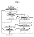
- engine control unit 30 determines whether or not variable operating angle control mechanism 10 is permitted to be driven, and engine control unit 30 controls variable operating angle control mechanism 10 based on the result of determination.
- Step S1 engine control unit 30 determines whether or not ignition switch 36 or starting switch 37 is in an ON state.
- Step S2 whether or not the engine is in a stopped state is determined based on whether or not output of the pulse signal is stopped from crank angle sensor 33 for a predetermined time or more.
- Step S2 when engine control unit 30 determines that the engine is in the stopped state, the flow goes to Step S3, and engine control unit 30 clears a counter which counts the number of outputs from crank angle sensor 33.
- Step S4 engine control unit 30 determines whether or not the pulse signal is output from crank angle sensor 33.
- Step S6 engine control unit 30 determines whether or not the counter value has reached a predetermined number of times.
- engine control unit 30 determines that the engine rotation has started according to the starting operation, and the flow goes to Step S7.
- Engine control unit 30 permits variable operating angle control mechanism 10 to do drive control, i.e., permits motor 17 to do the rotational control of control shaft 13 (see Fig. 5).
- variable operating angle control mechanism 10 When the engine is not rotated, even if motor 17 is driven, variable operating angle control mechanism 10 is not moved due to the large friction and accordingly, the large amount of current must pass through motor 17.
- variable operating angle control mechanism 10 is operated in response to the driving of the motor 17.
- engine control unit 30 makes the determination of the start of the engine rotation to permit the drive of motor 17, the change in operating angle and lift of intake valve 2 performed by variable operating angle control mechanism 10 is not largely delayed to the engine starting operation, the operating angle and lift can be immediately changed to optimum values in the engine starting state, and the high starting property of the engine can be maintained.
- engine control unit 30 makes the determination of the start of the engine rotation based on the pulse signal of crank angle sensor 33, the determination of the start of the engine rotation can be immediately made with high accuracy.
- Step S7 is a process of permitting motor 17 to be driven from the engine rotation state.
- motor 17 is driven when all the permission conditions including other permission conditions are satisfied.
- Step S6 when engine control unit 30 determines that the counter value does not reach the predetermined number of times, the flow goes to Step S8.
- Step S8 engine control unit 30 determines whether or not the engine is rotated while at least the predetermined time has elapsed since starting switch 37 is turned on.
- Whether or not the engine is rotated is determined based on whether or not the pulse signal of crank angle sensor 33 is constantly output for the predetermined time or more.
- Step S7 engine control unit 30 permits the drive of motor 17 even if the counter value does not reach the predetermined number of times.
- the determination of the start of the engine rotation is made based on the pulse signal of crank angle sensor 33.
- the engine has the characteristics in which a starter is driven to lower the battery voltage by turning on starting switch 37 and then the battery voltage is recovered by starting the engine rotation, it is also possible that the determination of the start of the engine rotation is made by monitoring a change in the battery voltage.
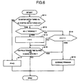
- Figure 6 is a flowchart showing an embodiment in which the determination of the start of the engine rotation is made based on the battery voltage to permit the drive of motor 17.
- Step S11 engine control unit 30 determines whether or not ignition switch 36 or starting switch 37 is in the ON state. When the ignition switch 36 or starting switch 37 is in the ON state, the flow goes to Step S12.
- Step S12 engine control unit 30 determines whether or not a battery voltage VB is lower than a threshold.
- the flow goes to Step S13, and flag F is set at 1,
- the threshold is preferably set based on the battery voltage VB before the starting operation of the engine.
- flag F is set at 0 in Step S17.
- Step S12 when engine control unit 30 determines that the battery voltage VB is equal to or higher than the threshold, the flow goes to Step S14.
- Step S14 engine control unit 30 determines whether or not flag F is 1.
- That flag F is 1 means that the battery voltage VB is lowered below the threshold once and then the battery voltage VB is increased to the threshold or higher.
- that flag F is 0 means that the battery voltage VB is held to be not lower than the threshold after the beginning of the starting operation of the engine.
- the engine exhibits the characteristics in which the battery voltage VB is restored in association with the engine rotation after the battery voltage VB is lowered in response to the start of the starter drive. Therefore, in the case where the battery voltage VB is increased to the threshold or higher after the battery voltage VB is lowered below the threshold once, engine control unit 30 determines that it is the timing for the start of the engine rotation.
- Step S15 engine control unit 30 permits the drive control of variable operating angle control mechanism 10, i.e., permits rotation of control shaft 13 by motor 17 (see Fig. 7).
- Step S14 After flag F is set at 1 in Step S13, and when engine control unit 30 determines that flag F is 0 In Step S14, the flow goes to Step S16.
- Step S16 engine control unit 30 determines whether or not the engine is rotated while at least the predetermined time has elapsed since starting switch 37 is turned on.
- Whether or not the engine is rotated is determined based on whether the pulse signal of crank angle sensor 33 is constantly output for at least the predetermined time.
- Step S15 When the engine is rotated while at least the predetermined time has elapsed since starting switch 37 is turned on, the flow goes to Step S15 without waiting for the permission determination based on the battery voltage VB, and engine control unit 30 permits the drive control of variable operating angle control mechanism 10 (motor 17).
- the engine can be prevented from being left without the drive permission being made.
- variable operating angle control mechanism 10 (motor 17) at the faster timing of any one of the determination of the start of the engine rotation based on the pulse signal of the crank angle sensor 33 and the determination of the start of the engine rotation based on the battery voltage VB
- variable valve actuation mechanism is not limited to variable operating angle control mechanism 10 having the above configuration, and the engine valve in which the operating characteristics is varied by the variable valve actuation mechanism is not limited to the intake valve.
- Step S8 and Step S16 can be omitted.
Landscapes
- Engineering & Computer Science (AREA)
- Mechanical Engineering (AREA)
- General Engineering & Computer Science (AREA)
- Chemical & Material Sciences (AREA)
- Combustion & Propulsion (AREA)
- Output Control And Ontrol Of Special Type Engine (AREA)
- Valve Device For Special Equipments (AREA)
- Combined Controls Of Internal Combustion Engines (AREA)
Applications Claiming Priority (1)
| Application Number | Priority Date | Filing Date | Title |
|---|---|---|---|
| JP2005034780A JP4444138B2 (ja) | 2005-02-10 | 2005-02-10 | 可変動弁機構の制御装置 |
Publications (2)
| Publication Number | Publication Date |
|---|---|
| EP1703103A1 true EP1703103A1 (fr) | 2006-09-20 |
| EP1703103B1 EP1703103B1 (fr) | 2013-08-28 |
Family
ID=36097340
Family Applications (1)
| Application Number | Title | Priority Date | Filing Date |
|---|---|---|---|
| EP06002573.1A Ceased EP1703103B1 (fr) | 2005-02-10 | 2006-02-08 | Dispositif et procédé de commande de mécanisme variable de commande de soupape |
Country Status (4)
| Country | Link |
|---|---|
| US (1) | US7628127B2 (fr) |
| EP (1) | EP1703103B1 (fr) |
| JP (1) | JP4444138B2 (fr) |
| CN (1) | CN1818353B (fr) |
Families Citing this family (4)
| Publication number | Priority date | Publication date | Assignee | Title |
|---|---|---|---|---|
| JP4600935B2 (ja) * | 2006-08-30 | 2010-12-22 | 株式会社デンソー | 内燃機関の可変バルブタイミング制御装置 |
| JP4655036B2 (ja) * | 2006-12-27 | 2011-03-23 | トヨタ自動車株式会社 | 可変動弁機構の制御装置 |
| JP5054574B2 (ja) * | 2008-03-03 | 2012-10-24 | 川崎重工業株式会社 | エンジン及びそれを備える乗り物 |
| EP3220406B1 (fr) * | 2016-03-14 | 2018-10-03 | ABB S.p.A. | Bobine d'actionneur pour des applications basse tension ou moyenne tension |
Citations (6)
| Publication number | Priority date | Publication date | Assignee | Title |
|---|---|---|---|---|
| US6397803B1 (en) * | 2001-02-22 | 2002-06-04 | Mitsubishi Denki Kabushiki Kaisha | Valve timing control system for internal combustion engine |
| EP1273770A2 (fr) * | 2001-07-06 | 2003-01-08 | C.R.F. Società Consortile per Azioni | Moteur diesel multicylindre avec commande de soupapes variable |
| JP2004092420A (ja) | 2002-08-29 | 2004-03-25 | Toyota Motor Corp | 内燃機関の始動制御装置 |
| EP1464830A1 (fr) * | 2003-03-31 | 2004-10-06 | Ford Global Technologies, Inc., A subsidiary of Ford Motor Company | Méthode de commande d'un moteur avant et après son arrêt |
| EP1493908A2 (fr) * | 2003-07-03 | 2005-01-05 | HONDA MOTOR CO., Ltd. | Dispositif de commande pour un moteur à combustion interne |
| JP2005034780A (ja) | 2003-07-17 | 2005-02-10 | Fuji Electric Holdings Co Ltd | メタン発酵処理方法及び装置 |
Family Cites Families (7)
| Publication number | Priority date | Publication date | Assignee | Title |
|---|---|---|---|---|
| JPH09209724A (ja) | 1996-02-02 | 1997-08-12 | Toyota Motor Corp | 内燃機関のバルブタイミング制御装置 |
| US6302085B1 (en) * | 1998-03-02 | 2001-10-16 | Unisia Sec's Corporation | Apparatus and method for detecting crank angle of engine |
| JP4394764B2 (ja) * | 1999-02-15 | 2010-01-06 | 日立オートモティブシステムズ株式会社 | 内燃機関の可変動弁装置 |
| JP2001355469A (ja) * | 2000-06-15 | 2001-12-26 | Unisia Jecs Corp | 内燃機関の可変動弁装置 |
| JP2003336530A (ja) | 2002-05-17 | 2003-11-28 | Denso Corp | 内燃機関の吸排気バルブ制御装置 |
| US7107951B2 (en) * | 2002-10-25 | 2006-09-19 | Denso Corporation | Variable valve timing control device of internal combustion engine |
| DE502004000216D1 (de) | 2003-04-01 | 2006-02-02 | Zf Sachs Ag | Doppelkupplungseinrichtung und Radiallagerungskonzept hierfür |
-
2005
- 2005-02-10 JP JP2005034780A patent/JP4444138B2/ja not_active Expired - Fee Related
-
2006
- 2006-02-08 EP EP06002573.1A patent/EP1703103B1/fr not_active Ceased
- 2006-02-09 US US11/349,912 patent/US7628127B2/en not_active Expired - Fee Related
- 2006-02-10 CN CN2006100074405A patent/CN1818353B/zh not_active Expired - Fee Related
Patent Citations (6)
| Publication number | Priority date | Publication date | Assignee | Title |
|---|---|---|---|---|
| US6397803B1 (en) * | 2001-02-22 | 2002-06-04 | Mitsubishi Denki Kabushiki Kaisha | Valve timing control system for internal combustion engine |
| EP1273770A2 (fr) * | 2001-07-06 | 2003-01-08 | C.R.F. Società Consortile per Azioni | Moteur diesel multicylindre avec commande de soupapes variable |
| JP2004092420A (ja) | 2002-08-29 | 2004-03-25 | Toyota Motor Corp | 内燃機関の始動制御装置 |
| EP1464830A1 (fr) * | 2003-03-31 | 2004-10-06 | Ford Global Technologies, Inc., A subsidiary of Ford Motor Company | Méthode de commande d'un moteur avant et après son arrêt |
| EP1493908A2 (fr) * | 2003-07-03 | 2005-01-05 | HONDA MOTOR CO., Ltd. | Dispositif de commande pour un moteur à combustion interne |
| JP2005034780A (ja) | 2003-07-17 | 2005-02-10 | Fuji Electric Holdings Co Ltd | メタン発酵処理方法及び装置 |
Also Published As
| Publication number | Publication date |
|---|---|
| CN1818353A (zh) | 2006-08-16 |
| JP4444138B2 (ja) | 2010-03-31 |
| US7628127B2 (en) | 2009-12-08 |
| JP2006220078A (ja) | 2006-08-24 |
| EP1703103B1 (fr) | 2013-08-28 |
| CN1818353B (zh) | 2010-12-15 |
| US20060174849A1 (en) | 2006-08-10 |
Similar Documents
| Publication | Publication Date | Title |
|---|---|---|
| US7188594B2 (en) | Apparatus and method for controlling variable valve actuation mechanism | |
| EP2057363B1 (fr) | Système de réglage de distribution variable et procédé de commande | |
| US8165784B2 (en) | Apparatus and method for learning reference position of variable valve unit | |
| US7980214B2 (en) | Control device for electrically driven variable valve timing apparatus | |
| JP5096096B2 (ja) | 可変動弁機構の制御装置 | |
| US7600418B2 (en) | Sensor adjusting method and system for variable valve mechanism | |
| US7513229B2 (en) | Apparatus for and method of controlling variable valve mechanism | |
| US7628127B2 (en) | Apparatus and method for controlling variable valve actuation mechanism | |
| US8525463B2 (en) | Malfunction determination device for motor control system | |
| US7322323B2 (en) | Valve actuation control apparatus for internal combustion engine | |
| JP4019818B2 (ja) | 可変動弁機構のセンサ異常検出装置 | |
| JP3756327B2 (ja) | 油圧式可変バルブタイミング機構の診断装置 | |
| JP4424372B2 (ja) | アクチュエータの制御装置 | |
| JP4880556B2 (ja) | 可変動弁機構の制御装置 | |
| JP4985514B2 (ja) | アクチュエータの制御装置 | |
| JP4525579B2 (ja) | 内燃機関のバルブ特性制御装置 | |
| JPH06317117A (ja) | 可変バルブタイミング制御装置の自己診断装置 | |
| JP4764186B2 (ja) | 可動部材の基準位置学習装置 | |
| JP2006170033A (ja) | 可変動弁機構の制御装置 | |
| JP2008291747A (ja) | 診断装置 | |
| JPH08261027A (ja) | 内燃機関の制御装置 | |
| JPS59113223A (ja) | 内燃機関のバルブタイミング制御装置 |
Legal Events
| Date | Code | Title | Description |
|---|---|---|---|
| PUAI | Public reference made under article 153(3) epc to a published international application that has entered the european phase |
Free format text: ORIGINAL CODE: 0009012 |
|
| AK | Designated contracting states |
Kind code of ref document: A1 Designated state(s): AT BE BG CH CY CZ DE DK EE ES FI FR GB GR HU IE IS IT LI LT LU LV MC NL PL PT RO SE SI SK TR |
|
| AX | Request for extension of the european patent |
Extension state: AL BA HR MK YU |
|
| 17P | Request for examination filed |
Effective date: 20070223 |
|
| 17Q | First examination report despatched |
Effective date: 20070321 |
|
| AKX | Designation fees paid |
Designated state(s): DE FR |
|
| RBV | Designated contracting states (corrected) |
Designated state(s): DE |
|
| GRAP | Despatch of communication of intention to grant a patent |
Free format text: ORIGINAL CODE: EPIDOSNIGR1 |
|
| INTG | Intention to grant announced |
Effective date: 20130409 |
|
| RIN1 | Information on inventor provided before grant (corrected) |
Inventor name: OKAMOTO, NAOKI C/O AUTOMOTIVE SYSTEMS,ENGINE I.P.D |
|
| GRAS | Grant fee paid |
Free format text: ORIGINAL CODE: EPIDOSNIGR3 |
|
| GRAA | (expected) grant |
Free format text: ORIGINAL CODE: 0009210 |
|
| AK | Designated contracting states |
Kind code of ref document: B1 Designated state(s): DE |
|
| REG | Reference to a national code |
Ref country code: DE Ref legal event code: R096 Ref document number: 602006038069 Country of ref document: DE Effective date: 20131024 |
|
| REG | Reference to a national code |
Ref country code: DE Ref legal event code: R097 Ref document number: 602006038069 Country of ref document: DE |
|
| PLBE | No opposition filed within time limit |
Free format text: ORIGINAL CODE: 0009261 |
|
| STAA | Information on the status of an ep patent application or granted ep patent |
Free format text: STATUS: NO OPPOSITION FILED WITHIN TIME LIMIT |
|
| 26N | No opposition filed |
Effective date: 20140530 |
|
| REG | Reference to a national code |
Ref country code: DE Ref legal event code: R097 Ref document number: 602006038069 Country of ref document: DE Effective date: 20140530 |
|
| PGFP | Annual fee paid to national office [announced via postgrant information from national office to epo] |
Ref country code: DE Payment date: 20200227 Year of fee payment: 15 |
|
| REG | Reference to a national code |
Ref country code: DE Ref legal event code: R119 Ref document number: 602006038069 Country of ref document: DE |
|
| PG25 | Lapsed in a contracting state [announced via postgrant information from national office to epo] |
Ref country code: DE Free format text: LAPSE BECAUSE OF NON-PAYMENT OF DUE FEES Effective date: 20210901 |