EP1703109A2 - Kraftstoffeinspritzungssystem für Brennkraftmaschine mit Injektoren, die durch Kondensatoren betätigt werden - Google Patents
Kraftstoffeinspritzungssystem für Brennkraftmaschine mit Injektoren, die durch Kondensatoren betätigt werden Download PDFInfo
- Publication number
- EP1703109A2 EP1703109A2 EP06111264A EP06111264A EP1703109A2 EP 1703109 A2 EP1703109 A2 EP 1703109A2 EP 06111264 A EP06111264 A EP 06111264A EP 06111264 A EP06111264 A EP 06111264A EP 1703109 A2 EP1703109 A2 EP 1703109A2
- Authority
- EP
- European Patent Office
- Prior art keywords
- capacitor
- engine
- fuel
- capacitors
- injections
- Prior art date
- Legal status (The legal status is an assumption and is not a legal conclusion. Google has not performed a legal analysis and makes no representation as to the accuracy of the status listed.)
- Withdrawn
Links
- 238000002347 injection Methods 0.000 title claims abstract description 228
- 239000007924 injection Substances 0.000 title claims abstract description 228
- 239000003990 capacitor Substances 0.000 title claims abstract description 191
- 239000000446 fuel Substances 0.000 title claims abstract description 104
- 238000002485 combustion reaction Methods 0.000 claims abstract description 27
- 239000007921 spray Substances 0.000 claims description 12
- 238000000034 method Methods 0.000 claims description 3
- 238000004519 manufacturing process Methods 0.000 abstract description 5
- 230000001965 increasing effect Effects 0.000 description 9
- 238000004891 communication Methods 0.000 description 4
- 230000008859 change Effects 0.000 description 3
- 238000011960 computer-aided design Methods 0.000 description 3
- 230000003247 decreasing effect Effects 0.000 description 3
- 238000010586 diagram Methods 0.000 description 3
- 238000012986 modification Methods 0.000 description 3
- 230000004048 modification Effects 0.000 description 3
- 238000012544 monitoring process Methods 0.000 description 3
- 230000000052 comparative effect Effects 0.000 description 2
- 230000008878 coupling Effects 0.000 description 2
- 238000010168 coupling process Methods 0.000 description 2
- 238000005859 coupling reaction Methods 0.000 description 2
- 238000005507 spraying Methods 0.000 description 2
- 241001481828 Glyptocephalus cynoglossus Species 0.000 description 1
- 230000003197 catalytic effect Effects 0.000 description 1
- 230000007423 decrease Effects 0.000 description 1
- 238000013461 design Methods 0.000 description 1
- 230000002708 enhancing effect Effects 0.000 description 1
- 238000009434 installation Methods 0.000 description 1
- 238000013519 translation Methods 0.000 description 1
- 238000011144 upstream manufacturing Methods 0.000 description 1
Images




Classifications
-
- F—MECHANICAL ENGINEERING; LIGHTING; HEATING; WEAPONS; BLASTING
- F02—COMBUSTION ENGINES; HOT-GAS OR COMBUSTION-PRODUCT ENGINE PLANTS
- F02D—CONTROLLING COMBUSTION ENGINES
- F02D41/00—Electrical control of supply of combustible mixture or its constituents
- F02D41/30—Controlling fuel injection
- F02D41/38—Controlling fuel injection of the high pressure type
- F02D41/40—Controlling fuel injection of the high pressure type with means for controlling injection timing or duration
- F02D41/402—Multiple injections
-
- F—MECHANICAL ENGINEERING; LIGHTING; HEATING; WEAPONS; BLASTING
- F02—COMBUSTION ENGINES; HOT-GAS OR COMBUSTION-PRODUCT ENGINE PLANTS
- F02D—CONTROLLING COMBUSTION ENGINES
- F02D41/00—Electrical control of supply of combustible mixture or its constituents
- F02D41/20—Output circuits, e.g. for controlling currents in command coils
-
- F—MECHANICAL ENGINEERING; LIGHTING; HEATING; WEAPONS; BLASTING
- F02—COMBUSTION ENGINES; HOT-GAS OR COMBUSTION-PRODUCT ENGINE PLANTS
- F02D—CONTROLLING COMBUSTION ENGINES
- F02D41/00—Electrical control of supply of combustible mixture or its constituents
- F02D41/20—Output circuits, e.g. for controlling currents in command coils
- F02D2041/2003—Output circuits, e.g. for controlling currents in command coils using means for creating a boost voltage, i.e. generation or use of a voltage higher than the battery voltage, e.g. to speed up injector opening
- F02D2041/2006—Output circuits, e.g. for controlling currents in command coils using means for creating a boost voltage, i.e. generation or use of a voltage higher than the battery voltage, e.g. to speed up injector opening by using a boost capacitor
-
- F—MECHANICAL ENGINEERING; LIGHTING; HEATING; WEAPONS; BLASTING
- F02—COMBUSTION ENGINES; HOT-GAS OR COMBUSTION-PRODUCT ENGINE PLANTS
- F02D—CONTROLLING COMBUSTION ENGINES
- F02D41/00—Electrical control of supply of combustible mixture or its constituents
- F02D41/02—Circuit arrangements for generating control signals
- F02D41/021—Introducing corrections for particular conditions exterior to the engine
- F02D41/0235—Introducing corrections for particular conditions exterior to the engine in relation with the state of the exhaust gas treating apparatus
- F02D41/027—Introducing corrections for particular conditions exterior to the engine in relation with the state of the exhaust gas treating apparatus to purge or regenerate the exhaust gas treating apparatus
-
- F—MECHANICAL ENGINEERING; LIGHTING; HEATING; WEAPONS; BLASTING
- F02—COMBUSTION ENGINES; HOT-GAS OR COMBUSTION-PRODUCT ENGINE PLANTS
- F02D—CONTROLLING COMBUSTION ENGINES
- F02D41/00—Electrical control of supply of combustible mixture or its constituents
- F02D41/22—Safety or indicating devices for abnormal conditions
- F02D41/221—Safety or indicating devices for abnormal conditions relating to the failure of actuators or electrically driven elements
-
- F—MECHANICAL ENGINEERING; LIGHTING; HEATING; WEAPONS; BLASTING
- F02—COMBUSTION ENGINES; HOT-GAS OR COMBUSTION-PRODUCT ENGINE PLANTS
- F02D—CONTROLLING COMBUSTION ENGINES
- F02D41/00—Electrical control of supply of combustible mixture or its constituents
- F02D41/30—Controlling fuel injection
- F02D41/38—Controlling fuel injection of the high pressure type
- F02D41/40—Controlling fuel injection of the high pressure type with means for controlling injection timing or duration
- F02D41/402—Multiple injections
- F02D41/405—Multiple injections with post injections
-
- Y—GENERAL TAGGING OF NEW TECHNOLOGICAL DEVELOPMENTS; GENERAL TAGGING OF CROSS-SECTIONAL TECHNOLOGIES SPANNING OVER SEVERAL SECTIONS OF THE IPC; TECHNICAL SUBJECTS COVERED BY FORMER USPC CROSS-REFERENCE ART COLLECTIONS [XRACs] AND DIGESTS
- Y02—TECHNOLOGIES OR APPLICATIONS FOR MITIGATION OR ADAPTATION AGAINST CLIMATE CHANGE
- Y02T—CLIMATE CHANGE MITIGATION TECHNOLOGIES RELATED TO TRANSPORTATION
- Y02T10/00—Road transport of goods or passengers
- Y02T10/10—Internal combustion engine [ICE] based vehicles
- Y02T10/40—Engine management systems
Definitions
- the present invention relates generally to a fuel injection system for internal combustion engines which is designed to spray fuel into cylinders of the engine multiple times in each combustion cycle, and more particularly, to a compact structure of such a system designed to energize injectors using capacitors and a production method thereof.
- One of the pilot and main injections may overlap the post injection between the two of the cylinders sharing one of the capacitors. Increasing of the cylinders of the engine may, thus, result in a difficulty in completing the pilot, main, and post injections in all the cylinders of the engine.
- Each of the capacitors is required to have a capacitance great enough to complete all the injections, thus requiring the need for installation of the large-sized capacitors in the fuel injection system. This also results in an increased overall size of the fuel injection system.
- a fuel injection system for an internal combustion engine which may be installed in automotive vehicles.
- the fuel injections system comprises: (a) an electronically controlled injector which works to spray fuel into a cylinder of an engine; (b) a first and a second capacitor selectively working to energize the injector to produce a spray of the fuel; (c) a switch circuit working to selectively connect one of the first and second capacitors to the injector to discharge the one to energize the injector; and (d) a controller working to control an operation of the injector to achieve a sequence of multiple injections of the fuel into the cylinder of the engine in each combustion cycle of the engine.
- the controller splits the sequence of multiple injections into a first injection group serving to produce a torque output of the engine and a second injection group serving to recover an after-treatment device of the engine.
- the controller actuates the switch circuit to selectively establish a connection of the first capacitor to the injector to achieve the first injection group and a connection of the second capacitor to the injector to achieve the second injection group.
- each of the first and second injection groups uses one of separate capacitors. For instance, fuel injections belonging to the second injection group are performed after fuel injections of the first injection group, e.g., during an exhaust stroke of the engine.
- each capacitor is required to complete all the fuel injections and have a greater capacitance. If the engine is a multi-cylinder engine, the time required to complete a single sequence of injections of fuel into each cylinder will be long, so that it overlap between any two or some of the cylinders.
- the fuel injection system of the invention is designed to use each of the first and second capacitors for one of the first and second injection groups in each combustion cycle of the engine even during the injection overlapping period, thus permitting the capacitance of each of the capacitors to be decreased. In other words, the size of the capacitors may be reduced. This allows a casing in which the fuel injection system is to be mounted to be reduced in size.
- the first capacitor is greater in capacitance than the second capacitor.
- the fuel injection system may further comprise a step-up transformer working to step-up a voltage, as produced by a battery, and supply the voltage to the first and second capacitors and a current circuit working to supply power, as produced by the battery, directly to the injector.
- the controller also works to monitor whether the first capacitor used to achieve the first injection group is malfunctioning or not. When it is determined that the first capacitor is malfunctioning, the controller controls the switch circuit to use the second capacitor to complete the first injection group.
- a fuel injection system for an internal combustion engine which comprises: (a) electronically controlled injectors each of which works to spray fuel into one of cylinders of an engine; (b) a first and a second capacitor selectively working to energize the injectors to produce sprays of the fuel; (c) a switch circuit working to selectively connect one of the first and second capacitors to a corresponding one of the injectors to discharge the one of the first and second capacitors to energize the corresponding one of the injectors; (d) a controller working to control an operation of each of the injectors to achieve a sequence of multiple injections of the fuel into the one of the cylinders of the engine in each combustion cycle of the engine, the controller splitting the sequences of multiple injections into a first injection group and a second injection group, the controller actuating the switch circuit to selectively establish a connection of the first capacitor to the injectors to achieve the first injection group and a connection of the second capacitor to the injectors to achieve the second injection group
- period of times in which the injections are performed at least partially overlap between the cylinders of the engine.
- Each of the first and second capacitors is used for one of the cylinders during the overlapping period of the injections.
- the first injection group serves to produce a torque output of the engine, while the second injection group serves to recover an after-treatment device of the engine.
- the fuel injection system further comprises a step-up transformer working to step-up a voltage, as produced by a battery, and supply the voltage to the first and second capacitors and a current circuit working to supply power, as produced by the battery, directly to the injectors.
- the first injection group is greater in number of the injections than the second injection group.
- the first capacitor is greater in capacitance than the second capacitor.
- the controller also works to monitor whether the first capacitor used to achieve the first injection group is malfunctioning or not. When it is determined that the first capacitor is malfunctioning, the controller controls the switch circuit to use the second capacitor to complete the first injection group.
- a method of producing the above described second fuel injection system characterized in that a capacitance of each of the first and second capacitors is determined which is required to complete a corresponding one of the first and second injection groups and permits the each of the first and second capacitors to be disposed in the casing designed to meet requirements on dimensions and shape thereof.
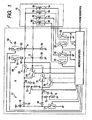
- a fuel injection system for internal combustion engines according to the first embodiment of the invention.
- the fuel injection system will be described below as being used, as an example, for a four-cylinder diesel engine 70.
- the fuel injection system is constructed by the part of an electronic control unit 1 typically mounted in an automotive vehicle.
- the electronic control unit 1 includes a microcomputer 2 which samples outputs of engine monitoring sensors to control operations of actuators of the engine 70.
- the electronic control unit 1 works to control energization of solenoids 6a, 6b, 6c, and 6d built in fuel injectors 4a, 4b, 4c, and 4d each of which injects the fuel into one of four combustion chambers of the engine 70.
- the energization of the solenoids 6a to 6d is achieved by a driver circuit 8 controlled by the microcomputer 2.
- the driver circuit 8 is equipped with a step-up transformer 10 working to increase the level (e.g., 12V) of voltage, as produced by a storage battery installed in the vehicle, up to a selected one (e.g., 85V).
- the step-up transformer 10 is made of a series-connected circuit made up of a coil 12 and a switch 14.
- the microcomputer 2 controls on- and off-operations of the switch 14 to increase the voltage of the battery.
- the drive circuit 8 also includes diodes 16 and 18 which are connected at anodes thereof between the coil 12 and the switch 14.
- the diode 16 is coupled at the cathode thereof to the solenoids 6a and 6b through a capacitor selection switch 20 and also to the solenoids 6c and 6d through a capacitor selection switch 22.
- the diode 18 is coupled at the cathode thereof to the solenoids 6a and 6b through a capacitor selection switch 24 and also to the solenoids 6c and 6d through a capacitor selection switch 26.
- the solenoids 6a to 6d are joined at terminals on one side to the step-up transformer 10 through the capacitor selection switches 20 to 26 and terminals on the other side to ground through injector selection switches 28, 30, 32, and 34.
- the driver circuit 8 also includes a main capacitor 40 and a sub-capacitor 42.
- the main capacitor 40 is joined at an end thereof between the diode 16 and a junction of the capacitor selection switches 20 and 22 and works to store electrical power stepped up by the step-up transformer 10.
- the sub-capacitor 42 is joined at an end thereof between the diode 18 and a junction of the capacitor selection switches 24 and 26 and works to store electrical power stepped up by the step-up transformer 10.
- the capacitor selection switch 20 works to selectively establish or block electrical communication between the main capacitor 40 and the solenoids 6a and 6b.
- the capacitor selection switch 22 works to selectively establish or block electrical communication between the main capacitor 40 and the solenoids 6c and 6d.
- the capacitor selection switch 24 works to selectively establish or block electrical communication between the sub-capacitor 42 and the solenoids 6a and 6b.
- the capacitor selection switch 26 works to selectively establish or block electrical communication between the sub-capacitor 42 and the solenoids 6c and 6d.
- the microcomputer 2 works to turn on at least one of the capacitor selection switches 20 to 26 to connect corresponding two of the solenoids 6a to 6d to the step-up transformer 10 and also turn on the injector selection switches 28 to 34 selectively to energize the solenoids 6a to 6d by means of the electric energy stored in the main capacitor 40 and the sub-capacitor 42.
- the energization of the solenoid 6a is achieved by turning on at least one of the capacitor selection switches 20 and 26 to connect the solenoids 6a and 6b to the step-up transformer 10 and also turning on the injector selection switch 28.
- a current circuit 50 is joined to a node a between the capacitor selection switches 20 and 26 and the solenoids 6a and 6b.
- the current circuit 50 works to maintain the energization of the solenoids 6a and 6b initiated by the main capacitor 40 and consists of a diode 52 supplying the power of the battery to the node a, a switch 54 coupling the diode 52 and the battery selectively, and a diode 56 connected to ground in the forward direction from the ground to the node a.
- a current circuit 60 is joined to a node b between the capacitor selection switches 22 and 24 and the solenoids 6c and 6d.
- the current circuit 60 works to maintain the energization of the solenoids 6c and 6c initiated by the sub-capacitor 60 and consists of a diode 62 supplying the power of the battery to the node b, a switch 64 coupling the diode 62 and the battery selectively, and a diode 66 connected to ground in the forward direction from the ground to the node b.
- the capacitor 40 is coupled with a series-connected resistor assembly 70.
- the microcomputer 2 monitors the voltage appearing at the node c of the series-connected resistor assembly 70.
- the capacitor 42 is coupled with a series-connected resistor assembly 72.
- the microcomputer 2 monitors the voltage appearing at the node d of the series-connected resistor assembly 72.
- the microcomputer 2 also monitors voltages appearing at a node e downstream of the injector selection switches 28 and 30 and at a node f downstrearn of the injector selection switches 32 and 34. Specifically, the microcomputer 2 monitors the voltages appearing at the nodes c, d, e, and f to measure currents flowing through the solenoids 61 to 6d.
- Fig. 2(a) illustrates a change in current supplied to any one of the solenoids 6a to 6d.
- Fig. 2(b) illustrates on- and off-operations of any one of the capacitor selection switches 20 to 26.
- Fig. 2(c) illustrates on- and off-operations of the switch 54 of the current circuit 50 or the switch 64 of the current circuit 60.
- Fig. 2(d) illustrates on- and off-operations of any one of the injector selection switches 28 to 34.
- Fig. 2(e) illustrates on- and off-operations of the switch 14 of the step-up transformer 10.
- Fig. 2(f) illustrates a change in electrical energy stored in either of the capacitor 40 or 42.
- the capacitor selection switch 20 and the injector selection switch 28 When the capacitor selection switch 20 and the injector selection switch 28 are turned on at time t1, it will produce a current flow through the solenoid 6a.
- the amount or flow rate of current flowing through the solenoid 6a has the peak (e.g., 18A) and then decreases.
- the microcomputer 2 actuates the current circuit 50 to keep the current flowing through the solenoid 6a at a first intermediate flow rate (e.g., 8A) between times t3 and t4 and at a second intermediate flow rate (e.g., 4A) between times t5 and t6 which is smaller than the first intermediate flow rate.
- the microcomputer 2 turns off the injector selection switch 28. After time t7, the microcomputer 2 turns on and off the switch 14 of the step-up transformer 10 cyclically to charge the capacitor 40, so that the amount of electrical energy stored in the capacitor 40, as can be seen in Fig. 2(f), increases.
- each of the solenoids 6a to 6d causes a corresponding one of the fuel injectors 4a to 4d to produce a jet of fuel.
- Each of the fuel injectors 4a to 4d is controlled by the microcomputer 2 to produce a sequence of post injections following a torque producing injection sequence made up of pilot injections pi, a main injection mi, and an after-injection ai .
- the first to fourth cylinders of the engine are represented by #1 to #4, respectively.
- Fig. 3 illustrates, as an example, that the main injection mi is the greatest in quantity of fuel.
- the quantity of fuel to be sprayed by each of the injectors 4a to 4d depends upon the length of time for which a corresponding one of the solenoids 6a to 6d is energized by the current circuit 50 or 60.
- the sequence of post injections is to recover an after-treatment device installed in an exhaust system of the diesel engine.
- the sequence of post injections serves to increase the temperature of a diesel particulate filter (DPF) installed in the exhaust system to burn out particulate matters (PMs) trapped in the DPF to keep it free from clogging.
- the increasing of the temperature of the DPF is achieved by injecting the fuel into the engine at a time not producing a torque output of the engine, e.g., during an exhaust stroke of the engine.
- the microcomputer 2 initiates the sequence of post injections when the quantity of PMs in the DPF exceeds a selected upper limit. Specifically, the microcomputer 2 estimates the quantity of PMs based on operating conditions of the engine and initiates the post injections when the estimated quantity exceeds the upper limit.
- the fuel injection system of this embodiment is designed to control the operations of the capacitor selection switches 20 to 26 so that one of the capacitors 40 and 42 servers to achieve a main group of injections (i.e., the torque producing injection sequence), and the other serves to achieve a post group of injections (i.e., the post injection sequence) to recover the after-treatment device in the exhaust system of the engine.
- the main capacitor 40 is used for the main group of injections
- the sub-capacitor 42 is used for the post group of injections.
- each of the capacitors 40 and 42 to be decreased in capacitance as compared with a fuel injection system equipped with capacitors each of which is used to complete all of multiple injections of fuel into one of cylinders of the engine in each combustion cycle, thus allowing each of the capacitors 40 and 42 to be reduced in size and to be mounted in a compact casing of the electronic control unit 1 which is designed to meet tight requirements on dimensions and shape thereof.
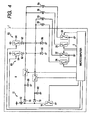
- Fig. 4 illustrates a comparative example of a fuel injection system which is equipped with two capacitors 80 and 82 each of which is used to energize two of the solenoids 6a to 6d.
- the same reference numbers as employed in Fig. 1 represent the same parts.
- the capacitors 80 and 82 are, unlike the fuel injection system of this embodiment, required to have the same greater capacitance because each of the capacitors 80 and 82 is used to achieve both the torque producing injection sequence and the post injection sequence.
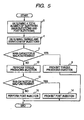
- Fig. 5 shows a sequence of logical steps or program to be executed in a cycle by the microcomputer 2 to control the injections of fuel into the engine 70.
- a total number of injections of fuel to be achieved in one cycle of each cylinder of the engine 70 is determined based on operating conditions of the engine 70 in a known manner. For instance, the number of torque producing injections, that is, a total number of the pilot injections pi , the main injection mi , and the after injection ai is determined as functions of the speed of the engine 70 and the quantity of fuel to be sprayed into the engine 70.
- the number of post injections is determined as functions of temperatures of and a difference between pressures of exhaust gasses flowing upstream and downstream of the DPF.
- step 4 controlled injection parameters such as a timing and a duration of each of the torque producing injections are determined.
- controlled injection parameters such as a timing and a duration of each of the torque producing injections are determined.
- step 6 it is determined whether the main capacitor 40 is malfunctioning or not. This determination may be made by monitoring the voltage appearing at the node c in Fig. 1. For instance, when the step-up transformer 10 is being operating or the capacitor selection switch 20 or 26 is in the on-state, but the voltage of the main capacitor 40 has a steady-state value, the microcomputer 2 determines that the main capacitor 40 is malfunctioning. If a YES answer is obtained in step 6 meaning that the main capacitor 40 is malfunctioning, then the routine proceeds to step 8 wherein the torque producing injections are prohibited. Alternatively, if a NO answer is obtained, then the routine proceeds to step 10 wherein the torque producing injections are initiated at the timings and continued for the durations, as determined in step 4, respectively.
- the microcomputer 2 when it is required to spray the fuel into the first cylinder #1 of the engine 70, the microcomputer 2, as already discussed with reference to Fig. 2, turns on the capacitor selection switch 20 and the injector selection switch 28 to discharge the capacitor 40 to energize the solenoid 6a. After the elapse of a given period of time, the microcomputer 2 turns off the capacitor selection switch 20 and then turns on the switch 54 of the current circuit 50 cyclically, as illustrated in Fig. 2(c), to supply the current from the battery to the solenoid 6a. This completes one of the torque producing injections. For instance, when it is required to inject the fuel into the first cylinder #1 of the engine 70 six times for producing a torque output of the engine 70, the above operation is repeated six times.
- step 12 it is determined whether the sub-capacitor 42 is malfunctioning or not. This determination may be made by monitoring the voltage appearing at the node d in Fig. 1. For instance, when the step-up transformer 10 is being operating or the capacitor selection switch 22 or 24 is in the on-state, but the voltage of the sub-capacitor 42 has a steady-state value, the microcomputer 2 determines that the sub-capacitor 42 is malfunctioning. If a YES answer is obtained in step 12 meaning that the sub-capacitor 42 is malfunctioning, then the routine proceeds to step 14 to prohibit the post injections from being initiated. Alternatively, if a NO answer is obtained, then the routine proceeds to step 16 wherein the post injections are initiated at the timings and each continued for the durations, as determined in step 4, respectively.
- the fuel injection system is equipped with the microcomputer 2 which works to control the operation of the drive circuit 8 so that the main capacitor 40 is discharged to achieve the torque producing injection sequence to produce the torque in the engine 70, and then the sub-capacitor 42 is discharged to achieve the post injections to recover the after-treatment device, such as the DPF, installed in the exhaust system of the engine 70.
- the microcomputer 2 works to control the operation of the drive circuit 8 so that the main capacitor 40 is discharged to achieve the torque producing injection sequence to produce the torque in the engine 70, and then the sub-capacitor 42 is discharged to achieve the post injections to recover the after-treatment device, such as the DPF, installed in the exhaust system of the engine 70.
- the main capacitor 40 used to achieve the torque producing injection sequence is greater in capacitance than the sub-capacitor 42 used to achieve the post injection sequence, thus permitting the size of the sub-capacitor 42 to be reduced.
- the electronic control unit 1 is equipped with the current circuits 50 and 60 working to supply the power of the battery directly to the fuel injectors 4a to 4d.
- the microcomputer 2 may, thus, regulate the duration of each of the multiple injections using the current circuits 50 and 60, thereby minimizing the quantity of electrical energy stored in the capacitors 40 and 42 to be consumed to achieve the multiple injections.
- the fuel injection system of the second embodiment will be described below which is designed to use the sub-capacitor 42 for the torque producing injection sequence when it is determined that the main capacitor 40 is malfunctioning.
- the fuel injection system is similar in structure to that of the first embodiment, and explanation thereof in detail will be omitted here.
- Fig. 6 shows a program to be executed in a cycle by the microcomputer 2 of the fuel injection system of the second embodiment to control the spraying of fuel into the engine 70.
- step 20 a total number of the torque producing and post injections to be achieved in one cycle of each cylinder of the engine 70 is determined in the same manner, as described in step 2 of Fig. 5, based on operating conditions of the engine 70.
- step 22 controlled injection parameters such as a timing and a duration of each of the torque producing injections are, like in step 4 of Fig. 5, determined.
- controlled injection parameters such as a timing and a duration of each of the torque producing injections are, like in step 4 of Fig. 5, determined.
- step 24 it is determined whether the main capacitor 40 is malfunctioning or not in the same manner, as discussed in step 6 of Fig. 5.
- step 24 If a NO answer is obtained in step 24 meaning that the main capacitor 40 is operating properly, then the routine proceeds to step 26 wherein the torque producing injections are initiated at the timings and continued for the durations, as determined in step 22, respectively, in the same manner, as described in the first embodiment.
- step 24 the routine also proceeds to step 28 wherein it is determined whether the sub-capacitor 42 is malfunctioning or not in the same manner, as in step 12 of Fig. 5. If a NO answer is obtained meaning that the sub-capacitor 42 is operating properly, then the routine proceeds to step 30 wherein the post injections are initiated at the timings and each continued for the durations, as determined in step 22, respectively. Alternatively, if a YES answer is obtained, then the routine proceeds to step 32 to prohibit the post injections from being performed.
- step 24 If a YES answer is obtained in step 24 meaning that the main capacitor 40 is malfunctioning, then the routine proceeds to step 34 wherein it is determined whether the sub-capacitor 42 is malfunctioning or not in the same manner, as in step 12 of Fig. 5. If a YES answer is obtained meaning that the sub-capacitor 42 is malfunctioning, then the routine proceeds to step 36 wherein the post injections are prohibited from being performed.
- step 34 if a NO answer is obtained in step 34 meaning that the sub-capacitor 42 is operating properly, then the routine proceeds to step 38 wherein the sub-capacitor 42 is used to achieve the torque producing injections.
- the microcomputer 2 when it is required to spray the fuel into the first cylinder #1 of the engine 70, the microcomputer 2 turns on the capacitor selection switch 26 and the injector selection switch 28 to discharge the sub-capacitor 42 to energize the solenoid 6a. After the elapse of a given period of time, the microcomputer 2 turns off the capacitor selection switch 26 and then turns on the switch 54 of the current circuit 50 cyclically to supply the current from the battery to the solenoid 6a. This completes one of the torque producing injections.
- step 38 After completion of all the torque producing injections in step 38, then the routine proceeds to step 40 wherein the post injection are prohibited from being performed.
- the electronic control unit 1 of the third embodiment will be described below.
- Figs. 7(a), 7(b), and 7(c) show examples of a casing 100 of the electronic control unit 1, respectively, which have dimensions and shapes different from each other, as selected according to specification requirements.
- the casing 100 is required to have various parts, such as a connector(s) 110, installed therein.
- the capacitors C1 and C2 to be disposed in the casing 100 are, therefore, subjected to restraints on dimensions thereof.
- Fig. 7(a) illustrates the example where the casing 1.00 is subject to a great restriction on the height thereof, therefore, one of the capacitors C1 and C2 is selected to be smaller in capacitance than the other, and the capacitors C1 and C2 are used to cover a sequence of injections broken down into a plurality of groups to be made in each cycle of the engine 70.
- the capacitor C1 having a greater capacitance is difficult to install vertically and thus laid horizontally.
- Fig. 7(b) illustrates the example similar to Fig. 7(a) where the casing 100 has a difficulty to install two capacitors together both of which have a greater capacitance, therefore, the capacitor C1 is selected to have a smaller capacitance, and the capacitors C1 and C2 are used to cover a sequence of injections broken down into a plurality of groups to be made in each cycle of the engine 70.
- the capacitor C2 having a greater capacitance is, however, laid vertically.
- Fig. 7(c) illustrates the example where a sequence of injections to be made using the electrical energy stored in the capacitors C1 and C2 in each cycle of the engine 70 is broken down into groups so that the capacitors C1 and C2 may have substantially the same capacitance.
- Fig. 8 shows a sequence of procedures for manufacturing the electronic control unit 1 of this embodiment.
- the profile or outer shape of the casing 100 is designed using CAD (Computer-Aided Design) software or system so as to meet requirements on dimensions and shape of the casing 100.
- CAD Computer-Aided Design
- step 52 all component parts of the electronic control unit 1, such as the drive circuit 8, the microcomputer 2, and the connector(s) 110, as illustrated in Fig. 1, except the capacitors C1 and C2 are installed within the casing 100 in the CAD system.
- the sequence of multiple injections is broken down into groups.
- the capacitors C1 and C2 are assigned to separate ones of the groups so that the capacitors C1 and C2 may not be used for the same cylinder of the engine 70 during the overlap period.
- all injections of fuel into the four cylinders in each cycle of the engine 70 are, as exemplified in Fig. 9, classified into two groups: one is enclosed by a dotted line and made using one of the capacitors C1 and C2, and the other by a chain line and made using the other one.
- the microcomputer 2 uses each of the capacitors C1 and C2 to spray the fuel into one of the cylinders of the engine 70 during the overlap period.
- first five shots of the injections are enclosed by the dotted line, while remaining four shots of the injections are enclosed by the chain line.
- the two groups are substantially identical in number of the injections, thus permitting the capacitors C1 and C2 to have substantially the same capacitance.
- step 52 the routine proceeds to step 54 wherein it is determined whether the casing 100 has space enough to accommodate all parts of the electronic control unit 1 or not.
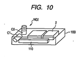
- Fig. 10 illustrates for the case where it is impossible to mount the capacitor C2 within the casing 100 completely. In such a case, a NO answer is obtained in step 54.
- the routine then proceeds to step 56 wherein the grouping of the injections in each of the cylinders of the engine 70 is altered. For instance, the grouping, as illustrated in Fig. 9, is altered into the one of Fig. 3. This permits the capacitor C2 to be reduced to a size small enough to be installed within the casing 100.
- step 56 the routine returns back to step 54. Specifically, the grouping in step 56 is made in a different manner until a YES answer is obtained in step 54. A part or all of the operations in steps 54 and 56 may be made automatically in the following steps.
- the injections to be made in each combustion cycle of the engine 70 be classified into groups according to the function or purpose thereof. For instance, the injections are classified into a post injection group, an after-injection group, a main injection group, and a pilot injection group. Two or some of the injections closer in time to each other may be selected to belong to the same group so that each capacitor is used for one of the cylinders of the engine 70 during a period of time in which the injections overlap in time sequence between the cylinders of the engine 70.
- the electronic control unit 1 made in the above manner may be so designed, like the second embodiment, that if one of the capacitors is determined to be malfunctioning, the other is, instead, used for the injections of fuel into the engine 70 to be made by the one.
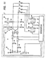
- Fig. 11 shows a modification of the electronic control unit 1 which is different from the one of Fig. 1 in that two capacitor selection switches 80 and 84 are used, each of which works to make a connection of one of the capacitors 40 and 42 with two of the solenoids 6a to 6d.
- the electronic control unit 1 also includes four diodes 90 connected in the illustrated manner. Other arrangements are identical with those in Fig. 1, and explanation thereof in detail will be omitted here.
- the current circuit 50 and 60 working to supply the power of the battery directly to the fuel injectors 4a to 4d may be omitted from the electronic control unit 1 in each of the above embodiments. This also offers the same advantages as described above.
- the number of groups of the injections of fuel into the engine 70 to be achieved in each combustion cycle using the electrical energy stored in the capacitors 40 and 42 is not limited to two (2).
- the number of capacitors used to energize the solenoids 6a to 6d is not limited to two.
- the number of the cylinders of the engine 70 may be changed.
- the structure of the drive circuit 8 may also be changed.
- a fuel injection system for internal combustion diesel engines is provided which is designed to produce a sequence of multiple injections of fuel into each cylinder of the engine.
- the sequence of multiple injections is split into, for example, a first and a second groups.
- the system is equipped with, for example, two capacitors which is discharged to energize electronically controlled fuel injectors to achieve the fuel injections.
- Each of the capacitors is used for one of the first and second groups, thereby permitting the capacitors to be reduced in capacitance or size thereof.
- a production method of such a system is also provided.
Landscapes
- Engineering & Computer Science (AREA)
- Chemical & Material Sciences (AREA)
- Combustion & Propulsion (AREA)
- Mechanical Engineering (AREA)
- General Engineering & Computer Science (AREA)
- Fuel-Injection Apparatus (AREA)
- Electrical Control Of Air Or Fuel Supplied To Internal-Combustion Engine (AREA)
- Combined Controls Of Internal Combustion Engines (AREA)
Applications Claiming Priority (1)
| Application Number | Priority Date | Filing Date | Title |
|---|---|---|---|
| JP2005076469A JP4274138B2 (ja) | 2005-03-17 | 2005-03-17 | 内燃機関の燃料噴射制御装置 |
Publications (2)
| Publication Number | Publication Date |
|---|---|
| EP1703109A2 true EP1703109A2 (de) | 2006-09-20 |
| EP1703109A3 EP1703109A3 (de) | 2010-12-22 |
Family
ID=36337436
Family Applications (1)
| Application Number | Title | Priority Date | Filing Date |
|---|---|---|---|
| EP06111264A Withdrawn EP1703109A3 (de) | 2005-03-17 | 2006-03-16 | Kraftstoffeinspritzungssystem für Brennkraftmaschine mit Injektoren, die durch Kondensatoren betätigt werden |
Country Status (2)
| Country | Link |
|---|---|
| EP (1) | EP1703109A3 (de) |
| JP (1) | JP4274138B2 (de) |
Cited By (1)
| Publication number | Priority date | Publication date | Assignee | Title |
|---|---|---|---|---|
| US20220090555A1 (en) * | 2020-09-18 | 2022-03-24 | Denso Corporation | Injection control device |
Families Citing this family (1)
| Publication number | Priority date | Publication date | Assignee | Title |
|---|---|---|---|---|
| JP7318594B2 (ja) * | 2020-06-29 | 2023-08-01 | 株式会社デンソー | 噴射制御装置 |
Citations (1)
| Publication number | Priority date | Publication date | Assignee | Title |
|---|---|---|---|---|
| JPH10510027A (ja) | 1995-09-22 | 1998-09-29 | ローベルト ボツシユ ゲゼルシヤフト ミツト ベシユレンクテル ハフツング | 内燃機関の制御方法及び装置 |
Family Cites Families (5)
| Publication number | Priority date | Publication date | Assignee | Title |
|---|---|---|---|---|
| DE19833830A1 (de) * | 1998-07-28 | 2000-02-03 | Bosch Gmbh Robert | Verfahren und Vorrichtung zur Steuerung wenigstens eines Magnetventils |
| US6407593B1 (en) * | 1999-06-30 | 2002-06-18 | Denso Corporation | Electromagnetic load control apparatus having variable drive-starting energy supply |
| JP4089119B2 (ja) * | 1999-06-30 | 2008-05-28 | 株式会社デンソー | 電磁負荷の制御装置 |
| JP2001227392A (ja) * | 2000-02-17 | 2001-08-24 | Denso Corp | 内燃機関の燃料噴射制御装置 |
| DE10058959B4 (de) * | 2000-11-28 | 2007-07-12 | Mtu Friedrichshafen Gmbh | Verfahren zur Überwachung einer Steuerschaltung |
-
2005
- 2005-03-17 JP JP2005076469A patent/JP4274138B2/ja not_active Expired - Fee Related
-
2006
- 2006-03-16 EP EP06111264A patent/EP1703109A3/de not_active Withdrawn
Patent Citations (1)
| Publication number | Priority date | Publication date | Assignee | Title |
|---|---|---|---|---|
| JPH10510027A (ja) | 1995-09-22 | 1998-09-29 | ローベルト ボツシユ ゲゼルシヤフト ミツト ベシユレンクテル ハフツング | 内燃機関の制御方法及び装置 |
Cited By (2)
| Publication number | Priority date | Publication date | Assignee | Title |
|---|---|---|---|---|
| US20220090555A1 (en) * | 2020-09-18 | 2022-03-24 | Denso Corporation | Injection control device |
| US11905907B2 (en) * | 2020-09-18 | 2024-02-20 | Denso Corporation | Injection control device |
Also Published As
| Publication number | Publication date |
|---|---|
| JP4274138B2 (ja) | 2009-06-03 |
| JP2006257965A (ja) | 2006-09-28 |
| EP1703109A3 (de) | 2010-12-22 |
Similar Documents
| Publication | Publication Date | Title |
|---|---|---|
| US7415964B2 (en) | Fuel injection control apparatus designed to minimize combustion noise of engine | |
| US7316220B2 (en) | Actuator drive system and fuel injection system | |
| JP2008032029A (ja) | 内燃機関の制御方法及び制御装置 | |
| ITTO940606A1 (it) | Metodo di autoinnesco della rigenerazione in un filtro particolato per un motore diesel con sistema d'iniezione a collettore comune. | |
| US8788179B2 (en) | Emission deterioration informing device | |
| US20100199752A1 (en) | Injector control performance diagnostic systems | |
| JP2935499B2 (ja) | ディーゼル機関用ピエゾ式噴射弁の駆動装置 | |
| CN101684757A (zh) | 一种车用柴油机电磁式高压共轨喷射系统电子控制单元 | |
| JP4930637B2 (ja) | 内燃機関の燃料噴射制御装置 | |
| US6450149B1 (en) | Method and apparatus for controlling overlap of two fuel shots in multi-shot fuel injection events | |
| EP1703109A2 (de) | Kraftstoffeinspritzungssystem für Brennkraftmaschine mit Injektoren, die durch Kondensatoren betätigt werden | |
| US7051699B2 (en) | Split mode operation for fuel injection systems | |
| DE102009041535B4 (de) | Kraftstoffeinspritzung-Steuergerät und Kraftstoffeinspritzung-Steuersystem für einen Verbrennungsmotor | |
| JP3573001B2 (ja) | 電磁負荷の制御装置 | |
| CN101684758A (zh) | 一种车用柴油机压电式高压共轨喷射系统电子控制单元 | |
| JP5997222B2 (ja) | インジェクタ駆動装置 | |
| US6173692B1 (en) | Time delay ignition circuit for an internal combustion engine | |
| US5947078A (en) | Fuel control system for cylinder injection type internal combustion engine | |
| JP2008309077A (ja) | 燃料噴射弁の診断装置及び情報取得装置 | |
| US20070157906A1 (en) | Method for operating an internal combustion engine | |
| JP4103254B2 (ja) | 電磁負荷の駆動装置 | |
| JP4029537B2 (ja) | 内燃機関の燃料噴射制御装置 | |
| EP2770188A1 (de) | Verfahren und System zur Steuerung einer Kraftstoffeinspritzung | |
| JP5170317B2 (ja) | 内燃機関の燃料噴射制御装置 | |
| EP2233724A1 (de) | Elektronische Steuereinheit zur Steuerung eines Satzes von Brennstoffinjektoren |
Legal Events
| Date | Code | Title | Description |
|---|---|---|---|
| PUAI | Public reference made under article 153(3) epc to a published international application that has entered the european phase |
Free format text: ORIGINAL CODE: 0009012 |
|
| AK | Designated contracting states |
Kind code of ref document: A2 Designated state(s): AT BE BG CH CY CZ DE DK EE ES FI FR GB GR HU IE IS IT LI LT LU LV MC NL PL PT RO SE SI SK TR |
|
| AX | Request for extension of the european patent |
Extension state: AL BA HR MK YU |
|
| PUAL | Search report despatched |
Free format text: ORIGINAL CODE: 0009013 |
|
| AK | Designated contracting states |
Kind code of ref document: A3 Designated state(s): AT BE BG CH CY CZ DE DK EE ES FI FR GB GR HU IE IS IT LI LT LU LV MC NL PL PT RO SE SI SK TR |
|
| AX | Request for extension of the european patent |
Extension state: AL BA HR MK YU |
|
| AKX | Designation fees paid |
Designated state(s): DE FR IT |
|
| STAA | Information on the status of an ep patent application or granted ep patent |
Free format text: STATUS: THE APPLICATION IS DEEMED TO BE WITHDRAWN |
|
| 18D | Application deemed to be withdrawn |
Effective date: 20110623 |