EP1703152A2 - Linearführungslager - Google Patents
Linearführungslager Download PDFInfo
- Publication number
- EP1703152A2 EP1703152A2 EP06012318A EP06012318A EP1703152A2 EP 1703152 A2 EP1703152 A2 EP 1703152A2 EP 06012318 A EP06012318 A EP 06012318A EP 06012318 A EP06012318 A EP 06012318A EP 1703152 A2 EP1703152 A2 EP 1703152A2
- Authority
- EP
- European Patent Office
- Prior art keywords
- guide rail
- under
- seal
- movable element
- groove
- Prior art date
- Legal status (The legal status is an assumption and is not a legal conclusion. Google has not performed a legal analysis and makes no representation as to the accuracy of the status listed.)
- Withdrawn
Links
- 238000005096 rolling process Methods 0.000 claims abstract description 14
- 238000007789 sealing Methods 0.000 claims abstract description 10
- 238000000465 moulding Methods 0.000 claims description 15
- 239000000463 material Substances 0.000 claims description 10
- 229920001971 elastomer Polymers 0.000 description 4
- 229910000831 Steel Inorganic materials 0.000 description 2
- 239000000853 adhesive Substances 0.000 description 2
- 230000001070 adhesive effect Effects 0.000 description 2
- 239000000428 dust Substances 0.000 description 2
- 239000002184 metal Substances 0.000 description 2
- 239000010959 steel Substances 0.000 description 2
- 230000000694 effects Effects 0.000 description 1
- 239000000806 elastomer Substances 0.000 description 1
- 239000004519 grease Substances 0.000 description 1
- 238000009434 installation Methods 0.000 description 1
- 238000004519 manufacturing process Methods 0.000 description 1
- 210000002445 nipple Anatomy 0.000 description 1
- 230000003014 reinforcing effect Effects 0.000 description 1
- 229920003002 synthetic resin Polymers 0.000 description 1
- 239000000057 synthetic resin Substances 0.000 description 1
Images


Classifications
-
- F—MECHANICAL ENGINEERING; LIGHTING; HEATING; WEAPONS; BLASTING
- F16—ENGINEERING ELEMENTS AND UNITS; GENERAL MEASURES FOR PRODUCING AND MAINTAINING EFFECTIVE FUNCTIONING OF MACHINES OR INSTALLATIONS; THERMAL INSULATION IN GENERAL
- F16C—SHAFTS; FLEXIBLE SHAFTS; ELEMENTS OR CRANKSHAFT MECHANISMS; ROTARY BODIES OTHER THAN GEARING ELEMENTS; BEARINGS
- F16C29/00—Bearings for parts moving only linearly
- F16C29/08—Arrangements for covering or protecting the ways
- F16C29/084—Arrangements for covering or protecting the ways fixed to the carriage or bearing body movable along the guide rail or track
- F16C29/088—Seals extending in the longitudinal direction of the carriage or bearing body
-
- F—MECHANICAL ENGINEERING; LIGHTING; HEATING; WEAPONS; BLASTING
- F16—ENGINEERING ELEMENTS AND UNITS; GENERAL MEASURES FOR PRODUCING AND MAINTAINING EFFECTIVE FUNCTIONING OF MACHINES OR INSTALLATIONS; THERMAL INSULATION IN GENERAL
- F16C—SHAFTS; FLEXIBLE SHAFTS; ELEMENTS OR CRANKSHAFT MECHANISMS; ROTARY BODIES OTHER THAN GEARING ELEMENTS; BEARINGS
- F16C29/00—Bearings for parts moving only linearly
- F16C29/04—Ball or roller bearings
- F16C29/06—Ball or roller bearings in which the rolling bodies circulate partly without carrying load
- F16C29/0633—Ball or roller bearings in which the rolling bodies circulate partly without carrying load with a bearing body defining a U-shaped carriage, i.e. surrounding a guide rail or track on three sides
- F16C29/0635—Ball or roller bearings in which the rolling bodies circulate partly without carrying load with a bearing body defining a U-shaped carriage, i.e. surrounding a guide rail or track on three sides whereby the return paths are provided as bores in a main body of the U-shaped carriage, e.g. the main body of the U-shaped carriage is a single part with end caps provided at each end
- F16C29/0638—Ball or roller bearings in which the rolling bodies circulate partly without carrying load with a bearing body defining a U-shaped carriage, i.e. surrounding a guide rail or track on three sides whereby the return paths are provided as bores in a main body of the U-shaped carriage, e.g. the main body of the U-shaped carriage is a single part with end caps provided at each end with balls
- F16C29/0642—Ball or roller bearings in which the rolling bodies circulate partly without carrying load with a bearing body defining a U-shaped carriage, i.e. surrounding a guide rail or track on three sides whereby the return paths are provided as bores in a main body of the U-shaped carriage, e.g. the main body of the U-shaped carriage is a single part with end caps provided at each end with balls with four rows of balls
-
- F—MECHANICAL ENGINEERING; LIGHTING; HEATING; WEAPONS; BLASTING
- F16—ENGINEERING ELEMENTS AND UNITS; GENERAL MEASURES FOR PRODUCING AND MAINTAINING EFFECTIVE FUNCTIONING OF MACHINES OR INSTALLATIONS; THERMAL INSULATION IN GENERAL
- F16C—SHAFTS; FLEXIBLE SHAFTS; ELEMENTS OR CRANKSHAFT MECHANISMS; ROTARY BODIES OTHER THAN GEARING ELEMENTS; BEARINGS
- F16C29/00—Bearings for parts moving only linearly
- F16C29/04—Ball or roller bearings
- F16C29/06—Ball or roller bearings in which the rolling bodies circulate partly without carrying load
- F16C29/0633—Ball or roller bearings in which the rolling bodies circulate partly without carrying load with a bearing body defining a U-shaped carriage, i.e. surrounding a guide rail or track on three sides
- F16C29/0635—Ball or roller bearings in which the rolling bodies circulate partly without carrying load with a bearing body defining a U-shaped carriage, i.e. surrounding a guide rail or track on three sides whereby the return paths are provided as bores in a main body of the U-shaped carriage, e.g. the main body of the U-shaped carriage is a single part with end caps provided at each end
- F16C29/0638—Ball or roller bearings in which the rolling bodies circulate partly without carrying load with a bearing body defining a U-shaped carriage, i.e. surrounding a guide rail or track on three sides whereby the return paths are provided as bores in a main body of the U-shaped carriage, e.g. the main body of the U-shaped carriage is a single part with end caps provided at each end with balls
- F16C29/0642—Ball or roller bearings in which the rolling bodies circulate partly without carrying load with a bearing body defining a U-shaped carriage, i.e. surrounding a guide rail or track on three sides whereby the return paths are provided as bores in a main body of the U-shaped carriage, e.g. the main body of the U-shaped carriage is a single part with end caps provided at each end with balls with four rows of balls
- F16C29/0647—Ball or roller bearings in which the rolling bodies circulate partly without carrying load with a bearing body defining a U-shaped carriage, i.e. surrounding a guide rail or track on three sides whereby the return paths are provided as bores in a main body of the U-shaped carriage, e.g. the main body of the U-shaped carriage is a single part with end caps provided at each end with balls with four rows of balls with load directions in X-arrangement
-
- F—MECHANICAL ENGINEERING; LIGHTING; HEATING; WEAPONS; BLASTING
- F16—ENGINEERING ELEMENTS AND UNITS; GENERAL MEASURES FOR PRODUCING AND MAINTAINING EFFECTIVE FUNCTIONING OF MACHINES OR INSTALLATIONS; THERMAL INSULATION IN GENERAL
- F16C—SHAFTS; FLEXIBLE SHAFTS; ELEMENTS OR CRANKSHAFT MECHANISMS; ROTARY BODIES OTHER THAN GEARING ELEMENTS; BEARINGS
- F16C29/00—Bearings for parts moving only linearly
- F16C29/04—Ball or roller bearings
- F16C29/06—Ball or roller bearings in which the rolling bodies circulate partly without carrying load
- F16C29/0633—Ball or roller bearings in which the rolling bodies circulate partly without carrying load with a bearing body defining a U-shaped carriage, i.e. surrounding a guide rail or track on three sides
- F16C29/0652—Ball or roller bearings in which the rolling bodies circulate partly without carrying load with a bearing body defining a U-shaped carriage, i.e. surrounding a guide rail or track on three sides whereby the return paths are at least partly defined by separate parts, e.g. covers attached to the legs of the main body of the U-shaped carriage
- F16C29/0654—Ball or roller bearings in which the rolling bodies circulate partly without carrying load with a bearing body defining a U-shaped carriage, i.e. surrounding a guide rail or track on three sides whereby the return paths are at least partly defined by separate parts, e.g. covers attached to the legs of the main body of the U-shaped carriage with balls
- F16C29/0659—Ball or roller bearings in which the rolling bodies circulate partly without carrying load with a bearing body defining a U-shaped carriage, i.e. surrounding a guide rail or track on three sides whereby the return paths are at least partly defined by separate parts, e.g. covers attached to the legs of the main body of the U-shaped carriage with balls with four rows of balls
-
- F—MECHANICAL ENGINEERING; LIGHTING; HEATING; WEAPONS; BLASTING
- F16—ENGINEERING ELEMENTS AND UNITS; GENERAL MEASURES FOR PRODUCING AND MAINTAINING EFFECTIVE FUNCTIONING OF MACHINES OR INSTALLATIONS; THERMAL INSULATION IN GENERAL
- F16C—SHAFTS; FLEXIBLE SHAFTS; ELEMENTS OR CRANKSHAFT MECHANISMS; ROTARY BODIES OTHER THAN GEARING ELEMENTS; BEARINGS
- F16C2322/00—Apparatus used in shaping articles
- F16C2322/39—General buildup of machine tools, e.g. spindles, slides, actuators
Definitions
- the present invention relates to a linear guide bearing apparatus which is used as a linear guide in a machine tool and industrial machines.
- a guide bearing apparatus which is used as a linear guide in a machine tool and industrial machines
- a guide bearing apparatus which includes a guide rail, a slider serving as a movable element, and a plurality of balls serving as rolling elements.
- the guide rail extending in the axial direction of the apparatus includes two first raceway grooves respectively formed in the two side walls thereof.
- the slider includes not only two second raceway grooves disposed opposed to the first raceway grooves of the guide rail but also ball return grooves respectively connected continuously with the second raceway grooves through their associated curved grooves respectively formed in the two end portions of each of the second raceway grooves.
- the slider includes a slider main body and a pair of end caps respectively to be connected to the two end portions of the slider main body; and, the second raceway grooves and ball return grooves are respectively formed in the slider main body, while the curved grooves are respectively formed in the end caps.
- This slider can be disposed by fitting the guide rail with the slider from the upward direction thereof in such a manner that the slider can be moved freely.
- the plurality of balls are used to move the slider along the guide rail, while the balls are disposed in a circulation passage which is composed of the first raceway grooves, second raceway grooves, curved grooves and ball return grooves.
- a mounting structure for mounting the under-seals there is conventionally known a mounting structure in which under-seal support grooves are formed in the end caps and the two end portions of the under-seals are respectively inserted into the under-seal support grooves.
- the present invention aims at eliminating the drawbacks found in the above-mentioned conventional linear guide bearing apparatus. Accordingly, it is an object of the invention to provide a linear guide bearing apparatus which can reduce the flexion of the under-seals due to their own weights.
- a linear guide bearing apparatus having a guide rail including a first raceway groove and extending in an axial direction of the linear guide bearing apparatus a movable element including a second raceway groove opposed to the first raceway groove and a rolling element return groove connected continuously with the second raceway groove through curved grooves respectively formed in the two end portions of the second raceway groove, the movable element being movably fitted with the guide rail, a plurality of rolling elements loaded in a circulation passage including the first raceway groove, the second raceway groove, the curved grooves, and the rolling element return groove for moving the movable element along the guide rail and, an under-seal disposed in the movable element for sealing a space between the guide rail and the movable element, wherein the under-seal includes a sliding contact portion elastically contacted with the guide rail to thereby receive an upward-going force from the guide rail.
- the under-seal since the under-seal includes a sliding contact portion which can be elastically contacted with the guide rail to thereby receive an upward-going force from the guide rail, the downward-going flexion of the guide rail due to its own weight can be restricted due to the upward-going force given to the guide rail by the sliding contact portion of the under-seal.
- a groove portion may be formed in the guide rail, the sliding contact portion being contacted with the groove portion.
- two end portions of the under-seal in the longitudinal-direction thereof may be supported on the movable element.
- at least one portion of a middle portion of the under-seal in the longitudinal-direction thereof may be supported on the movable element.
- the under-seal may be formed of a single material.
- the under-seal may be formed of a single material obtained from a molding with the section shape being uniform in the longitudinal direction thereof. In this case, a previously manufactured molding can be cut to a required length when it is used.
- the under-seal may include a lip which extends in the same direction as the sliding contact portion and may be slidingly contacted with the guide rail.
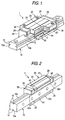
- the present linear guide bearing apparatus 1 includes a guide rail 10, a slider 20 serving as a movable element, balls 30 serving as rolling elements, and under-seals 40.
- the guide rail 10 which extends in the axial direction thereof, is made of steel having a long-and-narrow shape; and, in the width-direction two side portions thereof, for example, in the two side walls 10a thereof, there are formed first raceway grooves 12 along the axial direction thereof.
- the slider 20 includes a slider main body 21 and a pair of end caps 25 respectively connected to the longitudinal-direction two end portions of the slider main body 21.
- the slider main body 21 and end caps 25 respectively include sleeve portions 22, 26 on the two side portions thereof, while they are respectively formed so as to have a substantially U-shaped section.
- second raceway grooves 23 which are respectively opposed to their associated first raceway grooves 12 of the guide rail 10.
- ball return grooves 24 formed of holes which penetrate through the sleeve portions 22.
- the pair of end caps 25 are respectively moldings formed of synthetic resin or the like and, in the end caps 25, there are respectively formed curved grooves (not shown) which are connected continuously withthelongitudinal-direction two end portions of their associated second raceway grooves.
- the ball return grooves 24 are connected continuously with the second raceway grooves 23 through the curved grooves.
- a circulation passage C which is composed of the first raceway grooves 12, second raceway grooves 23, curved grooves and ball return grooves 24, there are disposed a plurality of balls 30 which are made of steel or the like.
- a grease nipple mounting hole (not shown).
- reference character 29 designates a reinforcing plate.
- the lower end portions of the inner walls 22a of the slider main body 21, as shown in Fig. 3, are formed as inclined walls 22b which respectively extend fine and long in the axial direction of the slider main body 21. Also, in the lower end portions of the end caps 25 as well, there are formed inclined walls 26a which are substantially parallel to the inclined walls 22b of the slider main body 21.
- each of the end caps 25 On the lower side of the sleeve portion 26 of each of the end caps 25, there is integrally disposed a projecting portion 27 which projects downwardly of the lower wall 22c of each of the sleeve portions 22 of the slider main body 21; and, in the projecting portion 27, there is formed an under-seal support groove 27a.
- the under-seal support groove 27a is formed in the extension of the wall surface of the inclined wall 22b and can be fitted with the support portion 40b of an under-seal 40 (which will be discussed later).
- This projecting portion 11 includes an inclined surface 11a which extends fine and long in such a manner that it is opposed to and parallel to the inclined wall 22b of the slider main body 21.
- This projecting portion 11 includes an inclined surface 11a which extends fine and long in such a manner that it is opposed to and parallel to the inclined wall 22b of the slider main body 21.
- Each under-seal 40 is disposed along the inclined wall 22b of the slider main body 21 and is used to seal a space between the side wall 10a of the guide rail 10 and the inner wall 22a of the slider main body 21 so as to prevent dust from entering between them.
- This under-seal 40 as shown in Fig. 3, includes a sliding contact portion 40a to be contacted with the inclined surface 11a of the side wall 10a of the guide rail 10, and a support portion 40b which can be inserted into the under-seal support groove 27a to be supported thereby; and, the under-seal 40 has a substantially corner-like section.
- the under-seal 40 is formed of a molding 34 the section shape of which is uniform in the longitudinal direction thereof; and, the molding 34 may be cut to a required length when it is used.
- the molding 34 there can be used an extruded molding, a drawn molding, or an injected molding.
- the molding 34 is cut to a length slightly longer than the length of the slider main body 21 to thereby provide the under-seal 40.
- the molding 34 is formed of a single material having elasticity such as rubber or elastomer.
- the present linear guide bearing apparatus 1 is assembled in the following manner. That is, while loading a plurality of balls 30 into the circulation passage C, the two end caps 25 are respectively connected to the two end portions of the slider main body 21. The two end portions of the under-seals 40 are respectively inserted into the under-seal support grooves 27a of the end caps 25. Due to this, with the two end portions thereof supported, the under-seals 40 are disposed on the lower wall 21c of the slider main body 21 in the axial direction of the slider main body 21. The thus-structured slider 20 is fitted onto the guide rail 10 from the upward direction in such a manner that the slider 20 can be moved.
- the leading end portions of the sliding contact portions 40a of the under-seals 40 are respectively elastically contacted with the inclined walls 22b formed in the projecting portions 11 of the guide rail 10. This can seal a space between the side wall 10a of the guide rail 10 and the inner wall 22a of the slider main body 21.
- the sliding contact portion 40a of the under-seal 40 is contacted with the inclined surface 11a of the guide rail 10 from the obliquely upward direction. Therefore, to the sliding contact portion 40a which extends over the entire length of the under-seal 40, there is applied an obliquely-upward-going force as a reactive action from the inclined surface 11a of the guide rail 10.
- This upward-going force received from the guide rail 10 can restrict the longitudinal-direction middle portion of the under-seal 40 from being flexed due to its own weight.
- the under-seal 40 includes the sliding contact portion 40a which can be elastically contacted with the guide rail 10 to receive the upward-going force from the guide rail 10. This can reduce the flexing of the under-seal 40 due to its own weight and can seal well a space between the side wall 10a of the guide rail 10 and the inner wall 22a of the slider main body 21.
- the two end portions of the under-seal 40 are formed so as to be supported by the slider 20, the number of supporting portions is small, which can facilitate the installation of the under-seal 40.
- the under-seal 40 is formed of a single material, when compared with a seal material which is formed in such a manner that rubber is molded and bonded to a core bar, the under-seal 40 can be manufactured at a low cost and also it can be treated easily when it is scrapped.
- the under-seal 40 is formed of a single material obtained from a molding the section shape of which is uniform in the longitudinal direction thereof. Therefore, since a previously manufactured molding is cut to a required length as the need arises, the under-seal 40 can be manufactured at a low cost.
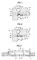
- an under-seal 41 as shown in Fig. 5, includes a sliding contact portion 41a to be contacted with the side wall 10a of the guide rail 10, and a support portion 41b to be supported by an under-seal support groove 27a.
- the support portion 41b is curved from the inclined wall 22b of the slider main body 21 along the lower wall 22c, and is inserted into the under-seal support groove 27a to be supported thereby.
- the under-seal support groove 27a is formed to have such a shape that allows the under-seal support groove 27a to be fitted with the support portion 41b.
- a groove portion 13a the section of which has a substantially semicircular shape.
- This groove portion 13a may be worked simultaneously when the first raceway groove 12 is worked, or may be worked when the guide rail 10 is worked by drawing, or may be separately worked by cutting or by metal forming.
- the projecting portion 11 of the guide rail 10 is omitted, the remaining portions of the present invention are the same in structure as those used in the previously described first embodiment. Therefore, the same parts are given like designations and thus the detailed description thereof is omitted here.
- the sliding contact portion 41a of the under-seal 41 is elastically contacted with the curved surface of the lower portion of the groove portion 13a formed in the side wall 10a of the guide rail 10 from the obliquely upward direction. For this reason, the sliding contact portion 41a of the under-seal 41 is given an obliquely-upward-going force from the groove portion 13a of the guide rail 10 as a reactive action.
- the sliding contact portion 41a of the under-seal 41 is elastically contacted with the curved surface of the lower portion of the groove portion 13a formed in the side wall 10a of the guide rail 10 from the obliquely upward direction.
- the sliding contact portion 41a of the under-seal 41 is formed so as to be contacted with the groove portion 13a, it is possible to omit the projecting portion 11 having the inclined surface 11a that is employed in the first embodiment. Therefore, in the present embodiment, the maximum width of the guide rail 10 can be reduced by an amount equivalent to the width of the projecting portion 11 over the maximum width of the guide rail 10 according to the first embodiment, thereby being able to reduce the manufacturing cost of the guide rail 10 accordingly.
- the groove portion 13a which is formed in the side wall 10a of the guide rail 10, is formed so as to have a substantially semicircular shape; however, the section shape of the groove portion 13a is not limited to a substantially semicircular shape.
- the section shape of the groove portion 13a is not limited to a substantially semicircular shape.
- another groove portion such as a groove portion 13b having a substantially triangular shape or a groove portion 13c having a substantially trapezoidal shape, provided that the shape of the groove portion is able to apply an obliquely-upward-going force to the sliding contact portion 41a as a reactive action.
- an under-seal 42 as shown in Fig. 7, includes a sliding contact portion 42a to be contacted with the side wall 10a of the guide rail 10, and a support portion 42b to be supported by an under-seal support groove 27a.
- the support portion 42b is curved from the inclined wall 22b of the slider main body 21 along the lower wall 22c, and is inserted into the under-seal support groove 27a to be supported thereby.
- the under-seal support groove 27a is formed to have such a shape that allows the under-seal support groove 27a to be fitted with the support portion 42b.
- the under-seal 42 further includes a lip 42c which extends upwardly of the sliding contact portion 42a in the same direction of the sliding contact portion 42a and also which can be slidingly contacted with the side wall 10a of the guide rail 10.
- the groove portion 14 is formed so as to have a substantially-triangular-shaped section; however, the section shape of the groove portion 14 may also be a substantially trapezoidal shape (see Fig. 5 and Fig. 6B).
- the projecting portion 11 of the guide rail 10 is omitted, the remaining portions of the present invention are the same in structure as those used in the previously described first embodiment. Therefore, the same parts are given like designations and thus the detailed description thereof is omitted here.
- the sealing property between the side wall 10a of the guide rail 10 and the inner wall 22a of the slider main body 21 can be enhanced further.
- an under-seal 43 as shown in Fig. 8, includes a sliding contact portion 43a to be contacted with the side wall 10a of the guide rail 10, and a support portion 43b to be supported by an under-seal support groove 27a.
- the support portion 43b is formed so as to be substantially parallel to the lower wall 22c of the slider main body 21, while the sliding contact portion 43a is inclined downwardly toward the groove portion 15 of the guide rail 10. By the way, the inclined wall 26a of the end cap 25 is omitted.
- the under-seal support groove 27a is formed so as to have a shape which allows the under-seal support groove 27a to be fitted with the support portion 43b.
- the section of the groove portion 15 of the guide rail 10 has a substantially trapezoidal shape having two inclined surfaces respectively formed on the upper and lower sides thereof, while the leading end portion of the sliding contact portion 43a is slidingly contacted with the lower-side inclined surface of the groove portion 15.
- the under-seal 43 includes a lip 43c which extends upwardly of the sliding contact portion 43a in the same direction of the sliding contact portion 43a and also which can be slidingly contacted with upper-side inclined surface of the groove portion 15 of the guide rail 10. That is, the lip 43c is inclined upwardly toward the groove portion 15 side of the guide rail 10.
- the section shape of the groove portion 15 is formed as a substantially trapezoidal shape; however, it is also possible to employ another shape, provided it has, on the upper and lower sides thereof, two inclined surfaces which can be slidingly contacted with the lip 43c and sliding contact portion 43a.
- the section shape of the groove portion 15 may also be a substantially semicircular shape or a substantially triangular shape (see Fig.
- the sealing property between the side wall 10a of the guide rail 10 and the inner wall 22a of the slider main body 21 can be enhanced.
- the support means for fixing the longitudinal-direction middle portion of the under-seal 43 is not limited to the rivet 35 but the longitudinal-direction middle portion of the under-seal 43 may also be supported on the slider using a screw or an adhesive.
- the under-seal 43 is supported at a portion of the longitudinal-direction central portion thereof; however, the number of the supporting portions of the under-seal 43 may be one or two or more.
- the remaining portions of the present invention are the same in structure as those used in the previously described first embodiment. Therefore, the same parts are given like designations and thus the detailed description thereof is omitted here.
- the under-seal 43 since the given portions of the longitudinal-direction middle portion of the under-seal 43 are supported on the slider main body 21, even in case where the slider main body 21. That is, the under-seal 43 is long, the flexing of the under-seal 43 due to its own weight can be prevented to thereby provide a good sealing condition between the guide rail and movable body.
- the under-seals 40 - 44 are respectively formed of a single material.
- the under-seals 40 - 44 there may also be employed an under-seal which can be obtained by molding and bonding rubber or the like onto a core bar made of a metal plate. In this case, the strength of the under-seals 40 - 44 can be enhanced.
- the sliding contact surface of the guide rail 10, with which the sliding contact portions 40a - 44a of the under-seals 40 - 44 can be elastically contacted is not limited to the inclined surface 11a or groove portions 13a, 13b, 13c, 14, 15 .
- the sliding contact surface may be a surface which is inclined or curved in a direction to support the sliding contact portions 40a - 44a from the lower side thereof.
- the longitudinal-direction two end portions of the sliding contact portions 40a - 44a of the under-seals 40 - 44 are inserted into the under-seal support grooves 27a formed in the end caps 25 to thereby support them on the slider 20.
- support of the two end portions of the under-seals 40 - 44 is not limited to this; for example, they may also be supported on the slider 20 using a rivet, a screw, or an adhesive.
- the flexing of the under-seal due to its own weight can be restricted to thereby be able to enhance the sealing property between the guide rail and movable body.
Landscapes
- Engineering & Computer Science (AREA)
- General Engineering & Computer Science (AREA)
- Mechanical Engineering (AREA)
- Bearings For Parts Moving Linearly (AREA)
- Sealing Of Bearings (AREA)
Applications Claiming Priority (2)
| Application Number | Priority Date | Filing Date | Title |
|---|---|---|---|
| JP2002118053A JP2003314547A (ja) | 2002-04-19 | 2002-04-19 | 直動案内軸受装置 |
| EP03009051A EP1357307B1 (de) | 2002-04-19 | 2003-04-17 | Linearführungslager |
Related Parent Applications (1)
| Application Number | Title | Priority Date | Filing Date |
|---|---|---|---|
| EP03009051A Division EP1357307B1 (de) | 2002-04-19 | 2003-04-17 | Linearführungslager |
Publications (2)
| Publication Number | Publication Date |
|---|---|
| EP1703152A2 true EP1703152A2 (de) | 2006-09-20 |
| EP1703152A3 EP1703152A3 (de) | 2007-08-08 |
Family
ID=28786732
Family Applications (2)
| Application Number | Title | Priority Date | Filing Date |
|---|---|---|---|
| EP03009051A Expired - Lifetime EP1357307B1 (de) | 2002-04-19 | 2003-04-17 | Linearführungslager |
| EP06012318A Withdrawn EP1703152A3 (de) | 2002-04-19 | 2003-04-17 | Linearführungslager |
Family Applications Before (1)
| Application Number | Title | Priority Date | Filing Date |
|---|---|---|---|
| EP03009051A Expired - Lifetime EP1357307B1 (de) | 2002-04-19 | 2003-04-17 | Linearführungslager |
Country Status (4)
| Country | Link |
|---|---|
| US (1) | US6902322B2 (de) |
| EP (2) | EP1357307B1 (de) |
| JP (1) | JP2003314547A (de) |
| DE (1) | DE60308085T8 (de) |
Families Citing this family (9)
| Publication number | Priority date | Publication date | Assignee | Title |
|---|---|---|---|---|
| JP2005291341A (ja) * | 2004-03-31 | 2005-10-20 | Nsk Ltd | 直動案内軸受装置及びアンダーシール |
| JP4307405B2 (ja) * | 2005-04-22 | 2009-08-05 | 日本トムソン株式会社 | 直動転がり案内ユニット |
| DE102005023998A1 (de) * | 2005-05-25 | 2006-12-14 | Schaeffler Kg | Hydrostatische Lagerung |
| US7380988B1 (en) * | 2005-11-15 | 2008-06-03 | Hiwin Technologies Corp. | Linear motion guide device having dust shield |
| DE102008047298A1 (de) * | 2008-09-16 | 2010-04-15 | Schaeffler Kg | Hydrostatische Profilschienenführung |
| JP5180799B2 (ja) * | 2008-12-10 | 2013-04-10 | 日本トムソン株式会社 | アクチュエータ |
| JP5358652B2 (ja) * | 2011-11-09 | 2013-12-04 | Thk株式会社 | 運動案内装置 |
| JP5874337B2 (ja) * | 2011-11-16 | 2016-03-02 | 日本精工株式会社 | リニアガイド装置のシール機構 |
| DE102013209294B3 (de) * | 2013-05-21 | 2014-07-24 | Schaeffler Technologies Gmbh & Co. Kg | Führungswagen einer Linearführung |
Family Cites Families (11)
| Publication number | Priority date | Publication date | Assignee | Title |
|---|---|---|---|---|
| JP2575891Y2 (ja) | 1992-08-20 | 1998-07-02 | 日本トムソン株式会社 | 直動転がり案内ユニット |
| US5429439A (en) | 1994-06-03 | 1995-07-04 | Hiwin Technologies Corp. | Linear ball guide assembly |
| EP0769627B1 (de) * | 1995-10-17 | 2000-08-02 | Deutsche Star GmbH | Linearführungseinrichtung |
| DE19615791A1 (de) | 1996-04-20 | 1997-10-23 | Schaeffler Waelzlager Kg | Linearwälzlager mit Längsdichtungen |
| WO1997043554A1 (en) * | 1996-05-13 | 1997-11-20 | Thk Co., Ltd. | Linear roller guide |
| EP0845610A4 (de) * | 1996-06-18 | 1999-09-15 | Thk Co Ltd | Linearführungseinrichtung mit rollen |
| JPH102332A (ja) * | 1996-06-18 | 1998-01-06 | Thk Kk | 複列ボールチェインを備えた直線運動案内装置 |
| JPH11336758A (ja) | 1998-05-28 | 1999-12-07 | Thk Co Ltd | 転がり案内装置 |
| DE19841668A1 (de) | 1998-09-11 | 2000-03-16 | Schaeffler Waelzlager Ohg | Linearwälzlager |
| US6170986B1 (en) | 1999-04-07 | 2001-01-09 | Chieftech Precision Co., Ltd. | Linear motion rolling guide device |
| JP4494601B2 (ja) * | 2000-07-21 | 2010-06-30 | Thk株式会社 | 転がり案内装置 |
-
2002
- 2002-04-19 JP JP2002118053A patent/JP2003314547A/ja active Pending
-
2003
- 2003-04-15 US US10/413,486 patent/US6902322B2/en not_active Expired - Fee Related
- 2003-04-17 DE DE60308085T patent/DE60308085T8/de not_active Expired - Fee Related
- 2003-04-17 EP EP03009051A patent/EP1357307B1/de not_active Expired - Lifetime
- 2003-04-17 EP EP06012318A patent/EP1703152A3/de not_active Withdrawn
Also Published As
| Publication number | Publication date |
|---|---|
| EP1357307A1 (de) | 2003-10-29 |
| US20030215166A1 (en) | 2003-11-20 |
| US6902322B2 (en) | 2005-06-07 |
| DE60308085T8 (de) | 2007-08-02 |
| DE60308085T2 (de) | 2006-12-21 |
| EP1703152A3 (de) | 2007-08-08 |
| EP1357307B1 (de) | 2006-09-06 |
| JP2003314547A (ja) | 2003-11-06 |
| DE60308085D1 (de) | 2006-10-19 |
Similar Documents
| Publication | Publication Date | Title |
|---|---|---|
| EP2613063B1 (de) | Führungsvorrichtung für linearbewegungen | |
| KR860001687B1 (ko) | 직선접동용 베어링 | |
| EP1808608B1 (de) | Verfahren zur herstellung einer linearführungsvorrichtung und laufschiene für die linearführungsvorrichtung | |
| US20080089622A1 (en) | Linear guide device | |
| EP1703152A2 (de) | Linearführungslager | |
| KR101280762B1 (ko) | 구름 안내 장치 및 그 제조 방법 | |
| US4929096A (en) | Linear guide apparatus | |
| EP2761197B1 (de) | Kugelgleithalterungs- und rückführungsanordnung | |
| KR20010041986A (ko) | 폴리머재 선형 안내체 | |
| JP4340617B2 (ja) | 直動案内ユニット | |
| CN115289186B (zh) | 复合式螺杆滑台 | |
| US20070269148A1 (en) | Guide Apparatus | |
| US6113272A (en) | Rolling motion guide apparatus | |
| CN101981334A (zh) | 用于滚动体的环绕导向装置和装备有该环绕导向装置的线性导向单元 | |
| US6109789A (en) | Linear slide | |
| US6709158B2 (en) | Linear motion guide unit with separator between any two adjoining rollers | |
| EP1403541A1 (de) | Linearwälzlager mit in einem flexibelen Käfig festgehaltenen Rollen | |
| JP2012067838A (ja) | 直動案内装置の仮軸用アタッチメント | |
| JP2007211900A (ja) | エンドシール及びそれを備えた直動案内装置 | |
| US5374127A (en) | Linear motion rolling guide unit | |
| US8382374B2 (en) | Sealing member for rolling device and rolling device | |
| JP4619226B2 (ja) | 転がり案内装置 | |
| US20060002637A1 (en) | Profiled rail guide | |
| US20050117820A1 (en) | Rolling element retainer | |
| JPH11287245A (ja) | リニアガイド用シール装置 |
Legal Events
| Date | Code | Title | Description |
|---|---|---|---|
| PUAI | Public reference made under article 153(3) epc to a published international application that has entered the european phase |
Free format text: ORIGINAL CODE: 0009012 |
|
| 17P | Request for examination filed |
Effective date: 20060614 |
|
| AC | Divisional application: reference to earlier application |
Ref document number: 1357307 Country of ref document: EP Kind code of ref document: P |
|
| AK | Designated contracting states |
Kind code of ref document: A2 Designated state(s): AT BE BG CH CY CZ DE DK EE ES FI FR GB GR HU IE IT LI LU MC NL PT RO SE SI SK TR |
|
| AX | Request for extension of the european patent |
Extension state: AL LT LV MK |
|
| PUAL | Search report despatched |
Free format text: ORIGINAL CODE: 0009013 |
|
| AK | Designated contracting states |
Kind code of ref document: A3 Designated state(s): AT BE BG CH CY CZ DE DK EE ES FI FR GB GR HU IE IT LI LU MC NL PT RO SE SI SK TR |
|
| AX | Request for extension of the european patent |
Extension state: AL LT LV MK |
|
| RIC1 | Information provided on ipc code assigned before grant |
Ipc: F16C 29/06 20060101ALI20070629BHEP Ipc: F16C 29/08 20060101AFI20060815BHEP |
|
| AKX | Designation fees paid |
Designated state(s): DE FR GB |
|
| 17Q | First examination report despatched |
Effective date: 20100121 |
|
| STAA | Information on the status of an ep patent application or granted ep patent |
Free format text: STATUS: THE APPLICATION IS DEEMED TO BE WITHDRAWN |
|
| 18D | Application deemed to be withdrawn |
Effective date: 20100601 |