EP1703269A1 - Dispositif de test de bas ou collants elastiques - Google Patents
Dispositif de test de bas ou collants elastiques Download PDFInfo
- Publication number
- EP1703269A1 EP1703269A1 EP06405095A EP06405095A EP1703269A1 EP 1703269 A1 EP1703269 A1 EP 1703269A1 EP 06405095 A EP06405095 A EP 06405095A EP 06405095 A EP06405095 A EP 06405095A EP 1703269 A1 EP1703269 A1 EP 1703269A1
- Authority
- EP
- European Patent Office
- Prior art keywords
- lever
- leg
- pressure sensors
- pressure
- bracket
- Prior art date
- Legal status (The legal status is an assumption and is not a legal conclusion. Google has not performed a legal analysis and makes no representation as to the accuracy of the status listed.)
- Withdrawn
Links
- 238000012360 testing method Methods 0.000 title claims abstract description 7
- 239000013013 elastic material Substances 0.000 title 1
- 230000007246 mechanism Effects 0.000 claims abstract description 49
- 239000004753 textile Substances 0.000 claims abstract description 6
- 210000002414 leg Anatomy 0.000 claims description 51
- 238000005259 measurement Methods 0.000 claims description 20
- 210000000689 upper leg Anatomy 0.000 claims description 13
- 244000309466 calf Species 0.000 claims description 11
- 238000000465 moulding Methods 0.000 claims description 7
- 238000011156 evaluation Methods 0.000 claims description 6
- 230000006835 compression Effects 0.000 claims description 2
- 238000007906 compression Methods 0.000 claims description 2
- 238000000034 method Methods 0.000 claims 1
- 210000002683 foot Anatomy 0.000 description 7
- 230000000712 assembly Effects 0.000 description 6
- 238000000429 assembly Methods 0.000 description 6
- XEEYBQQBJWHFJM-UHFFFAOYSA-N Iron Chemical compound [Fe] XEEYBQQBJWHFJM-UHFFFAOYSA-N 0.000 description 4
- 238000004519 manufacturing process Methods 0.000 description 3
- 210000003423 ankle Anatomy 0.000 description 2
- 210000001217 buttock Anatomy 0.000 description 2
- 230000008821 health effect Effects 0.000 description 2
- 229910052742 iron Inorganic materials 0.000 description 2
- 210000003127 knee Anatomy 0.000 description 2
- 241000549194 Euonymus europaeus Species 0.000 description 1
- 238000009530 blood pressure measurement Methods 0.000 description 1
- 238000004590 computer program Methods 0.000 description 1
- 238000001514 detection method Methods 0.000 description 1
- 230000000694 effects Effects 0.000 description 1
- 238000009659 non-destructive testing Methods 0.000 description 1
- 210000000056 organ Anatomy 0.000 description 1
- 210000002303 tibia Anatomy 0.000 description 1
- 210000001364 upper extremity Anatomy 0.000 description 1
Images




Classifications
-
- G—PHYSICS
- G01—MEASURING; TESTING
- G01N—INVESTIGATING OR ANALYSING MATERIALS BY DETERMINING THEIR CHEMICAL OR PHYSICAL PROPERTIES
- G01N3/00—Investigating strength properties of solid materials by application of mechanical stress
- G01N3/08—Investigating strength properties of solid materials by application of mechanical stress by applying steady tensile or compressive forces
-
- D—TEXTILES; PAPER
- D06—TREATMENT OF TEXTILES OR THE LIKE; LAUNDERING; FLEXIBLE MATERIALS NOT OTHERWISE PROVIDED FOR
- D06H—MARKING, INSPECTING, SEAMING OR SEVERING TEXTILE MATERIALS
- D06H3/00—Inspecting textile materials
- D06H3/16—Inspecting hosiery or other tubular fabric; Inspecting in combination with turning inside-out, classifying, or other handling
-
- G—PHYSICS
- G01—MEASURING; TESTING
- G01N—INVESTIGATING OR ANALYSING MATERIALS BY DETERMINING THEIR CHEMICAL OR PHYSICAL PROPERTIES
- G01N33/00—Investigating or analysing materials by specific methods not covered by groups G01N1/00 - G01N31/00
- G01N33/0078—Testing material properties on manufactured objects
- G01N33/0086—Clothes; Hosiery
-
- A—HUMAN NECESSITIES
- A61—MEDICAL OR VETERINARY SCIENCE; HYGIENE
- A61F—FILTERS IMPLANTABLE INTO BLOOD VESSELS; PROSTHESES; DEVICES PROVIDING PATENCY TO, OR PREVENTING COLLAPSING OF, TUBULAR STRUCTURES OF THE BODY, e.g. STENTS; ORTHOPAEDIC, NURSING OR CONTRACEPTIVE DEVICES; FOMENTATION; TREATMENT OR PROTECTION OF EYES OR EARS; BANDAGES, DRESSINGS OR ABSORBENT PADS; FIRST-AID KITS
- A61F13/00—Bandages or dressings; Absorbent pads
- A61F13/06—Bandages or dressings; Absorbent pads specially adapted for feet or legs; Corn-pads; Corn-rings
- A61F13/08—Elastic stockings; for contracting aneurisms
-
- G—PHYSICS
- G01—MEASURING; TESTING
- G01N—INVESTIGATING OR ANALYSING MATERIALS BY DETERMINING THEIR CHEMICAL OR PHYSICAL PROPERTIES
- G01N2203/00—Investigating strength properties of solid materials by application of mechanical stress
- G01N2203/02—Details not specific for a particular testing method
- G01N2203/026—Specifications of the specimen
- G01N2203/0262—Shape of the specimen
- G01N2203/0274—Tubular or ring-shaped specimens
Definitions
- the present invention relates to a device for testing elastic textile leg garments, in particular stockings or tights, medical compression stockings and support stockings.
- Elastic textile leg garments must be shaped so as to follow as closely as possible the contour of the leg of the person wearing the garment. For only in such a case can the legwear perform its function fully, without there being any points along the leg where the legwear either exerts too much or too little pressure.
- the circumference is also measured in the area of the buttocks and possibly also in the area of the waist. Based on these specifications, the legwear is then produced. According to this, however, it is also necessary to determine whether the specifications for the manufactured product have been complied with.
- the opposite longitudinal edges of the flattened stocking are attached to needles, which form two rows along the stocking length.
- These needles are movably mounted in such a way that the distance between two opposite Needles of the needle rows can be changed.
- the measurement as to whether the specifications have been met during the production of the stocking can, for example, be such that opposing needles are spaced apart from each other in accordance with the specification and that the tension in the stocking between two opposite needles is measured. So you can indeed determine whether the contour of the stocking has the course determined by the requirements. Because of the impingement on the needles the measured stocking is not for sale. Considering that such stockings are often custom-made, then the measurement of the finished stockings using the just mentioned device is ineffective.
- the object of the present device is to eliminate the mentioned as well as still further disadvantages of the prior art.
- Fig. 1 shows the model of a human leg, which can be used to demonstrate at which points or in which areas of the human body circumference measurements can be made in order to fit the leg pieces, e.g. to make medical stockings or tights.
- measurements are taken only above the foot.
- the circumference cH in the area of the buttocks and the circumference cT of the waist are also measured.
- the human legs differ from each other not only by the size of the circumference in said areas but also by the distances between these areas. These differences in distance are due to the different lengths of the legs. Therefore, these lengths are also determined during the measurements of a leg. These lengths are conveniently based on the underside of the foot, in particular on the underside of the heel.
- the area of the tether cB is located at a distance LB from the heel, etc., as indicated on the right in FIG.
- the present device for non-destructive testing of elastic Textile legwear is designed to allow adjustment of circumference values measured in the respective areas of a leg in the respective areas of the facility. Further, the present device allows to measure the amount of tension that prevail in those areas of the legwear corresponding to said areas of the leg. This guarantees that the finished product does not only exert its health-promoting effect, but that the legwear can also be worn comfortably.
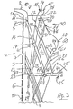
- Fig. 2 shows in a side view one of the embodiments of the present device.
- 3 shows an enlarged detail from the upper area of FIG. 2.
- the present device is largely represented by a so-called kinematic scheme.
- This scheme also demonstrates, inter alia, the principle of the present device for a particular area of the leg. This principle can then be used repeatedly in a device of this type to test several areas of a legwear.
- the present device comprises a base plate 1 on which a main support 2 of the present device is located.
- This main support 2 has an elongated body 3, which is designed substantially as a hollow rail.
- this rail 3 has an approximately U-shaped cross section.
- this rail 3 may also have an L-shaped or even a quadrangular cross-section.
- the main support 2 inserted in the base plate 1 is not a mandatory part of the present device.
- This front U-leg 4 is connected via a connecting web 5 connected to the second U-leg, which lies behind the front U-leg 4 and is therefore covered by this.
- At least the outer surface 6 of the connecting web 5 is rounded. It may be expedient, even the inner surface 7 of the connecting web 5 according to the rounded outer surface 6 of the same hollow perform.
- the upper end portion of the main support 2 and the rail 3 has a laterally bent portion 8.
- This rail section 8 is bent so that it lies above the connecting web 5 of the rail 3 and extends obliquely upward to the longitudinal direction of this rail.
- This substantially hook-shaped portion 8 of the main support 2 simulates the area of the tip of a foot.
- the region of the foot tip 8 can be embodied as a section of an obliquely upward-running, hollow shaped piece, for example made of a plastic. This fitting precedes the other components of this device described below.
- the cross-section of this molding may be arcuate, approximately as set forth above in connection with the cross-section of the main support 3.
- the present device further comprises measuring devices 10.
- the respective measuring device 10 comprises a lever mechanism and at least one pressure sensor 51.
- the actively participating in the measurement components of the respective measuring device 10 are each at that level L of a legwear where pressure measurements are to be performed.
- at least the active surfaces of the pressure sensors 51 are attached to the outer surface 6 of the rail 3. Therefore, the rail 3 can also be called as a carrier of the pressure sensors 51.
- the pressure sensors 51 are combined to form at least one vertically extending sensor device 50, the pressure sensors 51 forming a row within a sensor device 50. In the case shown in FIGS. 2 and 3, the sensor device is located However, it is more expedient if there are two sensor devices 50, of which one each is assigned to one of the flanks or one of the legs 4 of the carrier 3.
- the active surfaces of the pressure sensors 51 of the sensor devices 50 are located on the outer surface of the legs 4 of the carrier 3.
- Each of the pressure sensors 51 is individually electrically connected to a central evaluation unit (not shown).
- a first of the mentioned measuring devices 10 is shown, which is intended and designed for measuring the pressure in the area cB of the shackle.
- This area of the present device is shown enlarged in FIG. 3.
- the measuring device 10 also includes, among other things, a lever mechanism 11 (FIG. 3) which has a first lever 12.
- This lever 12 extends substantially vertically.
- the lower end 13 of this first lever 12 is pivotally mounted in the example shown on the main support 2 below the bend 8 by means of an axis 23. Expediently, this lower end 13 of the first lever 12 is pivotably mounted on the U-legs 4 of the support base 3 lying in the foreground in FIGS. 2 and 3.
- the upper end 14 of the first lever 12 is located approximately at the height of the hook-shaped extension 8 of the support base 3.
- the upper end 14 of the first lever 12 also has a laterally bent tail 15, which, however, is bent so that it is in a for Direction of the bend 8 on the support base body 3 opposite direction shows.
- the extension 15 at the upper end 14 of the first lever 12 simulates the heel of a foot or a legwear.
- the lever mechanism 11 further includes a second lever 16, which also extends substantially vertically. This second lever 16 crosses the first lever 12. These levers 12 and 16 are in the region of their intersection pivotally connected to each other by means of an axis 17. These thus associated levers 12 and 16 form a so-called scissors mechanism.
- the aforementioned axis 17 is in the illustrated case approximately in the middle of the length of said lever 12 and 16.
- the overhead end 18 of the second lever 16 of this scissor mechanism 11 is in the example shown on the inner surface 7 of the support base 3.
- the lower end 19 of the second lever 16 is connected to the spindle nut 24 of a spindle drive 25 for the value cB.
- This spindle drive 25 is oriented horizontally and it is attached to the support base body 3 approximately where the lower end 13 of the first lever 12 is pivotally mounted.
- the spindle drive 25 is arranged and configured to move the lower ends 13 and 19 of the levers 12 and 16 of the scissors mechanism 11 towards and away from each other. Accordingly, the distance between the offsets 8 and 15 at the upper ends of these levers 12 and 16 is reduced or increased.
- a rod 21 is pivotally mounted by means of a hinge 22 on the upper leg 20 of the first lever 12 at one end.
- This joint 22 is located below the bend 15 of the first lever 12, so that this joint 22 is located on the side facing away from the pressure sensors 51 side of lying above the pivot axis 17 leg 20 of the first lever 12.
- the hinge 22 is located at a distance 28 below the bend 15 at the upper end 14 of the first lever 12.
- the position of the heel 15 and thus the measurement level cB can be changed in a vertical direction, so that the length of the leg can be considered during the manufacture of legwear, the pivot bearing 23 of the lower end 13 of the first lever 12 on the spindle nut of a vertically oriented and firmly flared spindle drive 29 attached.
- a second measuring device 30 which is intended and designed to measure the pressure in the area cB1 of the beginning of the calf.
- This measuring device 30 also includes, inter alia, a lever mechanism 31, which has a first lever 32.
- This lever 32 extends substantially vertically.
- the lower end 33 of this first lever 32 is pivotally mounted.
- this end 13 of the first lever 32 is pivotally mounted on the U-legs 4 of the support base body 3 at the front in FIG. 2 or 3 by means of a shaft 43.
- the upper end 34 of the first lever 32 is located at a distance below the bend 15 on the first lever 12 and it is associated with the rod 27.
- a slot (not shown) is formed, which extends between the ends of this rod. This slot starts and ends at a distance from the ends of this rod 21. In this slot, the upper end 34 of the first lever 32 of the second measuring device 30 is mounted longitudinally displaceable.
- the second lever mechanism 31 further includes a second lever 36 which also extends substantially vertically. This second lever 36 crosses the first lever 32. These levers 32 and 36 are pivotally connected to each other in the region of their intersection by means of an axis 37. These thus associated levers 32 and 36 thus form a second scissors mechanism.
- the above-mentioned axis 37 is in the illustrated case above the middle of the length of said lever 32 and 36.
- the upper end 38 of the second lever 36 of this scissor mechanism 31 is supported in the illustrated case on the upper leg 20 of the first lever 12 of the first scissor mechanism 11 from , Under certain circumstances, it would be possible for the upper end 38 of the second lever 36 of this second scissor mechanism 31 to rest on the inner surface 7 of the support base body 3.
- the lower end 39 of the second lever 36 is connected to the spindle nut 44 of a second spindle drive 45 for the value cB1.
- This spindle drive 45 is oriented horizontally and it is mounted approximately where the lower end 33 of the first lever 32 is pivotally mounted by means of the shaft 43.
- the spindle drive 45 is arranged and configured to move the lower ends 33 and 39 of the levers 32 and 36 of the second scissors mechanism 31 toward and away from each other.
- the distance between the upper ends 34 and 38 of the levers 32 and 36 is reduced or increased.
- the upper end 34 of the first lever 32 moves to the right. Since this end 34 of the first lever 32 is mounted in the rod 21, an angle alpha, which extends between the upper leg 20 of the first lever 12 and the rod 21, increases.
- the distance between the back of the rod 21 and the same level pressure sensor 51 also changes. In this manner, different sizes of the circumference of the leg can be set in the range cB1 of the beginning of the calf.
- the bearing shaft 43 of the first lever 32 may be mounted on the spindle nut of the already mentioned vertically oriented linear drive 29 (Fig. 2).
- a third measuring device 60 which is intended and designed to measure the pressure in the area cC of the middle of the calf.
- This measuring device 60 also includes, among other things, a lever mechanism 61 which has a first lever 62.
- This lever 62 extends substantially vertically.
- the lower end 63 of this first lever 62 is pivotally mounted.
- this end 63 of the first lever 62 is pivotally mounted by means of a shaft 53.
- the upper end 64 of the first lever 62 is associated with an elongated molding 48.
- the overhead end 46 of this fitting 48 is slidably associated with the rod 21.
- the lower end 47 of the fitting 48 is pivotally mounted via a hinge 65 at the upper end 64 of the first lever 62.
- the molding 48 is designed so that its side facing away from the pressure sensors 51 side has a surface which is similar to the surface of the back of a calf.
- This third lever mechanism 61 also has a second lever 66, which also extends substantially vertically. This second lever 66 intersects the first lever 62. These levers 62 and 66 are pivotally connected to each other in the region of their intersection by means of an axis 67. These thus associated levers 62 and 66 thus form a third scissors mechanism.
- the overhead end 68 of the second lever 66 of this scissor mechanism 61 is slidably supported.
- the lower end 69 of the second lever 66 is connected to the spindle nut 54 of a third spindle drive 55 for the value cC. This spindle drive 55 is horizontally oriented and it is mounted approximately where the lower end 63 of the first lever 62 is pivotally mounted by means of the shaft 53.
- the spindle drive 55 is arranged and configured to move the lower ends 63 and 99 of the levers 62 and 66 of the third scissors mechanism 61 toward and away from each other. Accordingly, the distance between the upper ends 64 and 68 of the levers 62 and 66 is reduced or increased.
- the upper end 64 of the first lever 62 moves to the right. Since the lower end 47 of the mold 48 is connected to the upper end 64 of the first lever 62, the lower end 47 of the mold 48 also moves to the right, bringing the distance between the rear surface of the mold 48 and the same level Pressure sensors 51 increased. In this way, different sizes of the circumference of the leg in the area cC of the calf can be adjusted in the present device.
- the bearing shaft 63 of the first lever 62 is attached to a second vertically oriented linear bearing 49.
- FIG. 2 also shows a fourth measuring device 70 with which the dimensions in the region of a human thigh can be adjusted and with which the measurements of pressure between the regions cD and cG (FIG. 1) can be carried out.
- This measuring device 70 also includes, among other things, a second elongate shaped piece 88.
- the surface 89 of the shaped piece 88 facing away from the pressure sensors 51 has a course which corresponds to the course of the surface of the rear side of the thigh.
- the lower end 87 of this shaped piece 88 is connected to the nut of a further horizontally oriented spindle drive 84, which adjusts the setting cG (FIG. 1) in the upper region LG of the thigh.
- This measuring device 70 further comprises a fourth lever mechanism 71, which has a first lever 72.
- This lever 72 extends substantially vertically.
- the lower end 73 of this first lever 72 is pivotally mounted.
- this end 73 of the first lever 72 is pivotally mounted by means of a shaft 85.
- the upper end 74 of the first lever 72 is pivotally associated with the upper end 86 of the second elongated fitting 88.
- This fourth lever mechanism 71 further includes a second lever 76, which also extends substantially vertically. This second lever 76 crosses the first lever 72. These levers 72 and 76 are pivotally connected to each other in the region of their intersection by means of an axis 77. These thus associated levers 72 and 76 thus form a fourth scissors mechanism.
- the overhead end 78 of the second lever 76 of this scissors mechanism 71 is slidably supported.
- the lower end 79 of the second lever 76 is connected to the spindle nut of another spindle drive 95 for setting the value cD. This spindle drive 95 is horizontally oriented and it is mounted approximately where the lower end 73 of the first lever 72 is pivotally mounted by means of the shaft 85.
- the spindle drive 95 is arranged and configured to be able to move the lower ends 73 and 79 of the levers 72 and 76 of this scissor mechanism 71 towards and away from each other. Accordingly, the distance between the upper ends 74 and 78 of the levers 72 and 76 is reduced or increased.
- the upper end 74 of the first lever 72 moves to the right.
- the upper end 86 of the fitting 88 is connected to the upper end 74 of the first lever 72. therefore The upper end 86 of the fitting 88 also moves to the right, thus increasing the distance between the rear surface of the fitting 88 and the same level pressure sensors 51. In this way, different sizes of the circumference of the leg can be adjusted in the lower region LD of the thigh in the present device.
- the bearing shaft 85 of the first lever 72 and the spindle drive 84 are attached to another vertically oriented linear bearing 99.
- the levers of all scissors mechanisms can be designed as flat iron, so that the respective scissors mechanism is very flat. Consequently, a plurality of mutually shallow associated scissor mechanisms occupy only a small volume, so that a larger number of such scissor mechanisms can find space inside a legwear 80.
- Fig. 4 shows a purely schematic horizontal section AA through a further embodiment of the present invention, which corresponds to the device according to FIG. 2.
- the device according to FIG. 4 has the elongate and vertically extending carrier 90 for the pressure sensors 51.
- This carrier 90 is preceded by the lever mechanisms 10 described above.
- the upper end portion of this carrier 90 may include the aforesaid bend 8 ( Figure 2) which simulates the tip of a foot.
- the cross section of this support 90 is arcuate, wherein the central angle of this arc has expediently 180 degrees.
- Such a carrier 90 has two flanks 93 and 94 with two vertically extending edge portions 91 and 92.
- This carrier 90 simulates in the present legwear device the area of the tibia.
- the curved surface 89 on the abutment 88 shown in Fig. 4 simulates the rear surface of the femur in the present device.
- two groups 50 of pressure sensors 51 are provided, wherein the pressure sensors 51 within the respective group form a practically vertical row.
- Each of these rows 50 of pressure sensors 51 is assigned to the outside of one of the flanks 93 or 94 or to the outside of one of the edge portions 91 or 92 of the carrier 90.
- the carrier 90 together with the sensor rows 50 and the fitting 88 are surrounded by the leg clothing 80. Between the vertical edges 91 and 92 of the carrier 90 and the vertical edges 78 and 79 of the fitting 88 extend between the free-standing portions 81 and 82 of the over this stuffed legwear 80th
- the lower lying ends 79 of the second lever 76 of the fourth lever device 70 can be seen, which are connected to a common spindle drive 95 (not shown in Fig. 4).
- the other spindle drives 25, 45 and 55 as well as the linear bearings 29, 49 and 99, which have been described above in connection with FIGS. 2 and 3, may be common to the two arrangements 101 and 102.
- the spindle drives 25, 45 and 55 and the linear bearings 29, 49 and 99 between the assemblies 101 and 102 and the respective levers of the assemblies 101 and 102 are on the opposite sides of the spindle drives 25, 45 and 55 and the Linear bearings 29, 49 and 99 coupled.
- the embodiment of the present device shown in FIG. 4 does not require the main support 2 (FIGS. 2 and 3).
- legwear 80 for example, a stocking or the like. To be measured, then it is placed over the present device from above so that the extension 8 is located inside the top of the stocking and that the extension 15 at the upper end 14 of first lever 12 is located inside the heel of the stocking. The stocking of stocking 80 is then pulled further down over the remaining components of the present device. The legwear 80 is now on the front of the surface 6 of the carrier 90 with the Pressure sensors 50 and the back of the surface 89 of the lower mold piece 88 and possibly also on the surfaces of the other fittings or counter-bearing. In prior art devices leggings were measured in a laid flat state, which was not fair to the situation when wearing the legwear.
- the leg garment 80 is tested by the present device in the open state, ie in the same condition as if the leg garment were pulled on a leg.
- the legwear 80 to be tested surrounds the outer surfaces of both the carrier 90 and the anvil and the inside of the legwear exerts pressure on the pressure sensors 51.
- the pressure is advantageously measured by the sensors 50 arranged on the flanks 93 and 94 of the carrier 90, which results in a more accurate detection of the magnitude of the pressure in the vertically stacked levels or regions LB, LB1, LC, LF, LG, etc. of FIG Legwear 80 contributes.
- the effect c of the legwear 80 on the levels LB, LB1, LC, LF, LG, etc. can be measured by first determining certain distances between the carrier 90 and the active mechanical parts of the individual tensioning devices 10 opposite to the carrier 90 , 30, 60 and 70 after a leg garment 80 has been put on this device. Said distances correspond to values which are equal to those obtained during the measurement of the leg of the patient at said levels LB, LB1, LC, LF, LG, etc.
- the pressure values are read from those pressure sensors 51 or pressure sensor groups which are located at the individual levels LB, LB1, LC, LF, LG, etc. If the pressure readings are such that they allow the desired health effect and at the same time also a comfortable wearing of the legwear 80, then the legwear has been produced according to the specifications.
- the spindles not only of the horizontally acting spindle drives but also the spindles of the vertically acting linear bearings by electric motors, e.g. be driven by stepper motors. From the evaluation of these motors are controlled so that the distances between the pressure sensors 51 and the respective level LB, LB1, LC, LF, LG, etc. opposite active organs of the respective measuring device for the respective area of the legwear set quickly and accurately become.
- Pressure values which are supplied by the pressure sensors 51 lying on the stated levels LB, LB1, LC, LF, LG, etc., are set with the specifications applicable to the relevant level LB, LB1, LC, LF, LG, etc. of the patient's leg compared. From the result of this comparison, the quality of the legwear produced is concluded.
- the determination of the pressure value at the respective level LB, LB1, LC, LF, LG, etc. is based on the fact that the pressure sensors 51 or the groups of the pressure sensors 51 of the pressure measuring devices 50 are individually connected to the evaluation device. In order to determine the size of the pressure on the level LB, LB1, LC, LF, LG, etc. determined during the measurement of the patient's leg, those pressure sensors 51 or groups of the pressure sensors are interrogated by the evaluation device, which at the levels LB, LB1, LC, LF, LG etc. are. Thus, the pressure values sought can be determined quickly, accurately and without additional mechanical means.
- a computer program which, on the basis of the prescriptions determined during the measurement of the leg of a patient, determines the distances between the pressure sensors 51 and those at the respective level LB, LB1, LC, LF, LG, etc. automatically adjusts lying abutment in the respective measuring device for the respective area of the leg, then automatically read the pressure values at the respective level LB, LB1, LC, LF, LG etc. and then evaluate them.
- FIG. 5 shows a still further embodiment of the present device, the representation of which largely corresponds to the representation in FIG. 2.
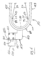
- Fig. 6 shows in a plan view the embodiment of the present device shown in Fig. 5, after the non-essential for this embodiment components of the present device have been omitted for the sake of clarity.
- a holding device 110 is arranged for this end part of the legwear. This area is located above the lower end of the carrier 3, which may be inserted in the base plate 1.
- the holding device 110 comprises a bracket 111 to which the edge of the open end portion of the legwear can be connected. This bracket 111 is in a horizontal plane and it is U-shaped.
- the bracket 111 has two mutually parallel legs 112 and 113. The one ends of these legs 112 and 113 are connected to each other by means of a web 114 to said U-shape.
- the web 114 is arcuate.
- a connection plate 115 is attached at one end, which also lies at least substantially in said horizontal plane.
- this connection plate 115 is L-shaped, so that it has two legs 116 and 117. The free end portion of one of the L-legs 117 of the connection plate 115 is connected to the web 114 of the bracket 111.
- the holding device 110 further comprises a mechanism 120, which for Adjustment of the position of the bracket 111 relative to the support 3 in the horizontal direction allows.
- the adjustment mechanism 120 comprises two vertically extending rods 121 and 122 which are substantially parallel to each other and which are associated with each other so that one of the rods can slide along the other rod.
- these rods 121 and 122 have a quadrangular cross-section and they are associated with one another via one of their side surfaces.
- Means 123 are provided, with the aid of which the set position of one of the rods relative to the other rod can be determined.
- These means 123 may comprise, for example, a screw and a nut.
- the bolt of the screw passes through the two rods 121 and 122.
- the position of the rods 121 and 122 to each other can be determined in such a way that a nut is tightened on the other end of the bolt.
- a longitudinal groove 124 is made in the side surface of one of the rods 121 to which the other rod 122 is assigned.
- the corresponding side surface of this other rod 122 is provided with a protruding comb 125 which projects from this side wall of the rod 122 and which is mounted longitudinally displaceably in the groove 124.
- the lower end portion of the first and lower rod 121 is fixed on or in the base plate 1.
- the free end portion of the second L-leg 116 of the connection plate 115 is connected to the bracket 111 to the upper end of the second rod 122.
- screw holes are executed in the end face of this end of the second rod 122 .
- the screw holes corresponding openings 126 are executed.
- Means screws (not shown), which pass through these openings 126, the free end portion of the second L-leg 116 may be attached to the end face of the second rod.
- two sensor devices 50 are provided, with the pressure sensors 51 within the respective group forming a substantially vertical row.
- One of each of these sensor rows 50 is assigned to one of the flanks 93 or 94 of the carrier 3 with the arc-shaped cross-section.
- the active surfaces of the sensors 51 of these rows 50 are located on the outside of the respective flank 93 or 94 of the carrier 3.
- the carrier 3 together with the sensor rows 50 are surrounded by the leg clothing 80, of which in Fig. 6, only the front portion thereof indicated is.
Landscapes
- Chemical & Material Sciences (AREA)
- Engineering & Computer Science (AREA)
- Health & Medical Sciences (AREA)
- Life Sciences & Earth Sciences (AREA)
- Biochemistry (AREA)
- Immunology (AREA)
- Pathology (AREA)
- Analytical Chemistry (AREA)
- Physics & Mathematics (AREA)
- General Health & Medical Sciences (AREA)
- General Physics & Mathematics (AREA)
- Materials Engineering (AREA)
- Textile Engineering (AREA)
- Food Science & Technology (AREA)
- Medicinal Chemistry (AREA)
- Force Measurement Appropriate To Specific Purposes (AREA)
- Treatment Of Fiber Materials (AREA)
- Investigating Strength Of Materials By Application Of Mechanical Stress (AREA)
Applications Claiming Priority (2)
| Application Number | Priority Date | Filing Date | Title |
|---|---|---|---|
| CH4322005 | 2005-03-14 | ||
| CH18132005 | 2005-11-14 |
Publications (1)
| Publication Number | Publication Date |
|---|---|
| EP1703269A1 true EP1703269A1 (fr) | 2006-09-20 |
Family
ID=36428282
Family Applications (1)
| Application Number | Title | Priority Date | Filing Date |
|---|---|---|---|
| EP06405095A Withdrawn EP1703269A1 (fr) | 2005-03-14 | 2006-03-03 | Dispositif de test de bas ou collants elastiques |
Country Status (5)
| Country | Link |
|---|---|
| US (1) | US7509874B2 (fr) |
| EP (1) | EP1703269A1 (fr) |
| JP (1) | JP2006258811A (fr) |
| BR (1) | BRPI0600769A (fr) |
| TW (1) | TW200643412A (fr) |
Cited By (5)
| Publication number | Priority date | Publication date | Assignee | Title |
|---|---|---|---|---|
| WO2012136845A1 (fr) * | 2011-04-07 | 2012-10-11 | Medi Gmbh & Co. Kg | Dispositif d'entraînement à la mise en place de matériel de compression |
| DE102012208640A1 (de) | 2012-05-23 | 2013-11-28 | Karl Otto Braun Gmbh & Co. Kg | Messvorrichtung zum Bestimmen des Kompressionsdrucks von Kompressionsbinden |
| DE102012208639A1 (de) | 2012-05-23 | 2013-11-28 | Karl Otto Braun Gmbh & Co. Kg | Messvorrichtung zum Bestimmen des Kompressionsdrucks von therapeutischen Kompressionsmaßnahmen, wie insbesondere Kompressionsstrümpfe oder Kompressionsbandagen |
| EP2887039A3 (fr) * | 2013-12-18 | 2015-07-01 | Peter Müller GmbH | Dispositif et procédé de mesure de la pression de contention de bas de contention et bandages de contention |
| CN114486719A (zh) * | 2022-03-30 | 2022-05-13 | 浙江理工大学 | 一种围度可调的柱形模拟肢体和弹力袜的压力测试方法 |
Families Citing this family (4)
| Publication number | Priority date | Publication date | Assignee | Title |
|---|---|---|---|---|
| CN102508058B (zh) * | 2011-10-10 | 2014-10-15 | 东华大学 | 一种可测量单纤维径向导电性和压缩性的微尺度握持器 |
| EP3417286B1 (fr) | 2016-03-17 | 2021-09-22 | Calik Denim Tekstil Sanayi Ve Ticaret Anonim Sirketi | Nouvel appareil d'essai de mesure de pression pour produits textiles conventionnels et techniques |
| US10307795B2 (en) * | 2016-05-04 | 2019-06-04 | Fabscrap, Inc. | Scalable systems and methods for classifying textile samples |
| CN106018084A (zh) * | 2016-05-20 | 2016-10-12 | 山东省纺织科学研究院 | 压缩袜压缩性能试验仪 |
Citations (5)
| Publication number | Priority date | Publication date | Assignee | Title |
|---|---|---|---|---|
| US4137763A (en) * | 1978-06-21 | 1979-02-06 | Rampon Products, Incorporated | Hosiery testing apparatus |
| GB2081321A (en) * | 1980-07-11 | 1982-02-17 | Ambrogini Piero | Inspecting and stretching apparatus for manufactured hosiery articles |
| EP0538588A1 (fr) * | 1991-09-24 | 1993-04-28 | August Krempel Söhne GmbH & Co. | Procédé et appareil pour étirer des collants sur une forme |
| FR2797393A1 (fr) * | 1999-08-10 | 2001-02-16 | Innothera Topic Int | Dispositif pour la mesure extensometrique, non destructive, des forces de contention susceptibles d'etre exercees par une orthese de type bas ou collant de contention |
| US6334363B1 (en) * | 1997-06-23 | 2002-01-01 | Innothera Topic International | Device for measuring pressure points to be applied by a compressive orthotic device |
Family Cites Families (7)
| Publication number | Priority date | Publication date | Assignee | Title |
|---|---|---|---|---|
| US2675703A (en) * | 1954-04-20 | Stocking testing device | ||
| US2369661A (en) * | 1942-10-14 | 1945-02-20 | Dangelmajer Charles | Means for testing resistance to run and tear formation |
| US2661877A (en) * | 1950-02-14 | 1953-12-08 | Paramount Textile Mach Co | Hosiery drying form |
| US3503257A (en) * | 1968-05-09 | 1970-03-31 | Pilot Res Corp | Garment testing apparatus |
| US3750291A (en) * | 1971-04-05 | 1973-08-07 | Us Industries Inc | Panty hose measuring means |
| JPS57161602A (en) * | 1981-03-31 | 1982-10-05 | Agency Of Ind Science & Technol | Measuring device for sizes of ready-made articles of clothing |
| US4491255A (en) * | 1983-05-20 | 1985-01-01 | Intech Corporation | Collapsible hosiery form |
-
2006
- 2006-03-03 EP EP06405095A patent/EP1703269A1/fr not_active Withdrawn
- 2006-03-06 TW TW095107386A patent/TW200643412A/zh unknown
- 2006-03-13 JP JP2006067740A patent/JP2006258811A/ja active Pending
- 2006-03-14 US US11/374,428 patent/US7509874B2/en not_active Expired - Fee Related
- 2006-03-14 BR BRPI0600769-4A patent/BRPI0600769A/pt not_active Application Discontinuation
Patent Citations (5)
| Publication number | Priority date | Publication date | Assignee | Title |
|---|---|---|---|---|
| US4137763A (en) * | 1978-06-21 | 1979-02-06 | Rampon Products, Incorporated | Hosiery testing apparatus |
| GB2081321A (en) * | 1980-07-11 | 1982-02-17 | Ambrogini Piero | Inspecting and stretching apparatus for manufactured hosiery articles |
| EP0538588A1 (fr) * | 1991-09-24 | 1993-04-28 | August Krempel Söhne GmbH & Co. | Procédé et appareil pour étirer des collants sur une forme |
| US6334363B1 (en) * | 1997-06-23 | 2002-01-01 | Innothera Topic International | Device for measuring pressure points to be applied by a compressive orthotic device |
| FR2797393A1 (fr) * | 1999-08-10 | 2001-02-16 | Innothera Topic Int | Dispositif pour la mesure extensometrique, non destructive, des forces de contention susceptibles d'etre exercees par une orthese de type bas ou collant de contention |
Cited By (8)
| Publication number | Priority date | Publication date | Assignee | Title |
|---|---|---|---|---|
| WO2012136845A1 (fr) * | 2011-04-07 | 2012-10-11 | Medi Gmbh & Co. Kg | Dispositif d'entraînement à la mise en place de matériel de compression |
| DE102012208640A1 (de) | 2012-05-23 | 2013-11-28 | Karl Otto Braun Gmbh & Co. Kg | Messvorrichtung zum Bestimmen des Kompressionsdrucks von Kompressionsbinden |
| DE102012208639A1 (de) | 2012-05-23 | 2013-11-28 | Karl Otto Braun Gmbh & Co. Kg | Messvorrichtung zum Bestimmen des Kompressionsdrucks von therapeutischen Kompressionsmaßnahmen, wie insbesondere Kompressionsstrümpfe oder Kompressionsbandagen |
| WO2013174855A1 (fr) | 2012-05-23 | 2013-11-28 | Karl Otto Braun Gmbh & Co. Kg | Dispositif de mesure pour déterminer la pression de compression exercée par des moyens de compression thérapeutiques, tels que des bas de contention ou des bandages compressifs |
| WO2013174860A1 (fr) | 2012-05-23 | 2013-11-28 | Karl Otto Braun Gmbh & Co. Kg | Dispositif de mesure permettant de déterminer la pression de compression de bandages compressifs |
| EP2887039A3 (fr) * | 2013-12-18 | 2015-07-01 | Peter Müller GmbH | Dispositif et procédé de mesure de la pression de contention de bas de contention et bandages de contention |
| CN114486719A (zh) * | 2022-03-30 | 2022-05-13 | 浙江理工大学 | 一种围度可调的柱形模拟肢体和弹力袜的压力测试方法 |
| CN114486719B (zh) * | 2022-03-30 | 2024-03-19 | 浙江理工大学 | 一种围度可调的柱形模拟肢体和弹力袜的压力测试方法 |
Also Published As
| Publication number | Publication date |
|---|---|
| US20070012120A1 (en) | 2007-01-18 |
| JP2006258811A (ja) | 2006-09-28 |
| US7509874B2 (en) | 2009-03-31 |
| BRPI0600769A (pt) | 2006-11-07 |
| TW200643412A (en) | 2006-12-16 |
Similar Documents
| Publication | Publication Date | Title |
|---|---|---|
| DE4423717C1 (de) | Vorrichtung zur Festlegung von Resektionsflächen am Femur und an der Tibia zur Vorbereitung einer Implantation einer Kniegelenkstotalendoprothese | |
| EP1408833A1 (fr) | Dispositif de mesure destine a determiner une contrainte irreguliere sur un corps humain en station debout | |
| WO1996018345A2 (fr) | Dispositif permettant de resserrer la peau | |
| EP1703269A1 (fr) | Dispositif de test de bas ou collants elastiques | |
| DE3827265C2 (fr) | ||
| DE60016370T2 (de) | Vorrichtung zur bestimmung der durch einen kompressionsstrumpf oder eine -strumpfhose ausgeübten kompressionskräfte | |
| DE3837667A1 (de) | Belastungstraeger fuer streckwerke von spinnmaschinen | |
| DE102007046895A1 (de) | Verfahren zur objektiven Bestimmung der körperlichen Konstitution einer Testperson sowie Testgerät hierzu | |
| DE69908617T2 (de) | Vorrichtung und verfahren zur messung der trageeigenschaften von strumpfwaren | |
| DE102015122069A1 (de) | Injektionsvorrichtung zur Verabreichung einer Injektion an einem Tier | |
| DE961740C (de) | Abschlagkamm fuer Handstrickapparate | |
| DE2457141A1 (de) | Einrichtung fuer die zustandspruefung an einem tabakstrang | |
| DE2411100A1 (de) | Schneidvorrichtung fuer industrienaehmaschinen mit einem ebenen maschinenbett | |
| DE281493C (fr) | ||
| DE102006046709B4 (de) | Verfahren zur Herstellung maßgeschneideter Bekleidungsstücke | |
| DE3533481A1 (de) | Trainingseinrichtung | |
| DE839333C (de) | Messvorrichtung zum Massnehmen fuer Jacken, Maentel oder aehnliche Kleidungssstuecke fuer Massschneider | |
| DE200260C (fr) | ||
| DE87626C (fr) | ||
| DE35755C (de) | Neuerung an Apparaten zum Maafsnehmen von Kleidungsstücken | |
| DE295972C (fr) | ||
| DE63905C (de) | Fufsmefsapparat | |
| DE548278C (de) | Verstellbare Modellpuppe | |
| DE46011C (de) | »Apparat zur Herstellung von Schnittmustern | |
| DE5928C (de) | Neuerungen an Strickmaschinen |
Legal Events
| Date | Code | Title | Description |
|---|---|---|---|
| PUAI | Public reference made under article 153(3) epc to a published international application that has entered the european phase |
Free format text: ORIGINAL CODE: 0009012 |
|
| AK | Designated contracting states |
Kind code of ref document: A1 Designated state(s): AT BE BG CH CY CZ DE DK EE ES FI FR GB GR HU IE IS IT LI LT LU LV MC NL PL PT RO SE SI SK TR |
|
| AX | Request for extension of the european patent |
Extension state: AL BA HR MK YU |
|
| 17P | Request for examination filed |
Effective date: 20070302 |
|
| 17Q | First examination report despatched |
Effective date: 20070404 |
|
| AKX | Designation fees paid |
Designated state(s): AT BE BG CH CY CZ DE DK EE ES FI FR GB GR HU IE IS IT LI LT LU LV MC NL PL PT RO SE SI SK TR |
|
| STAA | Information on the status of an ep patent application or granted ep patent |
Free format text: STATUS: THE APPLICATION IS DEEMED TO BE WITHDRAWN |
|
| 18D | Application deemed to be withdrawn |
Effective date: 20101001 |