EP1703346A2 - Module E/S de sécurité universel - Google Patents
Module E/S de sécurité universel Download PDFInfo
- Publication number
- EP1703346A2 EP1703346A2 EP06005406A EP06005406A EP1703346A2 EP 1703346 A2 EP1703346 A2 EP 1703346A2 EP 06005406 A EP06005406 A EP 06005406A EP 06005406 A EP06005406 A EP 06005406A EP 1703346 A2 EP1703346 A2 EP 1703346A2
- Authority
- EP
- European Patent Office
- Prior art keywords
- safety
- data
- component
- network
- backplane
- Prior art date
- Legal status (The legal status is an assumption and is not a legal conclusion. Google has not performed a legal analysis and makes no representation as to the accuracy of the status listed.)
- Withdrawn
Links
Images




Classifications
-
- G—PHYSICS
- G05—CONTROLLING; REGULATING
- G05B—CONTROL OR REGULATING SYSTEMS IN GENERAL; FUNCTIONAL ELEMENTS OF SUCH SYSTEMS; MONITORING OR TESTING ARRANGEMENTS FOR SUCH SYSTEMS OR ELEMENTS
- G05B19/00—Program-control systems
- G05B19/02—Program-control systems electric
- G05B19/04—Program control other than numerical control, i.e. in sequence controllers or logic controllers
- G05B19/042—Program control other than numerical control, i.e. in sequence controllers or logic controllers using digital processors
- G05B19/0428—Safety, monitoring
-
- G—PHYSICS
- G05—CONTROLLING; REGULATING
- G05B—CONTROL OR REGULATING SYSTEMS IN GENERAL; FUNCTIONAL ELEMENTS OF SUCH SYSTEMS; MONITORING OR TESTING ARRANGEMENTS FOR SUCH SYSTEMS OR ELEMENTS
- G05B2219/00—Program-control systems
- G05B2219/20—Pc systems
- G05B2219/21—Pc I-O input output
- G05B2219/21163—Test I-O if functional or safe value
-
- G—PHYSICS
- G05—CONTROLLING; REGULATING
- G05B—CONTROL OR REGULATING SYSTEMS IN GENERAL; FUNCTIONAL ELEMENTS OF SUCH SYSTEMS; MONITORING OR TESTING ARRANGEMENTS FOR SUCH SYSTEMS OR ELEMENTS
- G05B2219/00—Program-control systems
- G05B2219/20—Pc systems
- G05B2219/24—Pc safety
- G05B2219/24008—Safety integrity level, safety integrated systems SIL SIS
Definitions
- the subject invention relates to industrial controls. It finds particular application in conjunction with combining block and modular I/O, integrating standard and safety messages and bridging of such safety signals in an integrated control network, and will be described with particular reference thereto. However, it is to be appreciated that the present exemplary embodiment is also amenable to other like applications.
- Machine control employs digital and/or analog communication to exchange information across various networks.
- various protocols are employed with such networks to facilitate communication between a controller(s) and one or more control components such as I/O modules, drives, servos, switches, sensors, etc.
- Conventional protocols accept data from a source (e.g., controller) and package the data for transmission to one or more data recipients (e.g., control components).
- data recipients e.g., control components
- protocols have limited communication and typically are suitable only for certain layers within an automation pyramid and/or limited in their functionality (e.g., single master system running a master/slave protocol). This may result in barriers within the automation architecture that are difficult to penetrate and that require complex bridging devices without being able to fully bridge the gap between the various systems that are quite different in nature.
- Machine control typically includes various safety devices and associated controls that can be used to mitigate machine accidents that can harm an individual.
- Conventional systems typically hardwire pushbuttons (e.g., an e-stop) directly into a controller to handle emergency situations which could result in harm to an individual. In this manner, a user can shut down an operation by pressing the appropriate button.
- Safety signals can also be sent through various communication channels within a control system to prevent a potentially dangerous condition from occurring.
- Such automated intelligence relies on particular signal levels (values) in order to initiate such a related safety change.
- maintaining the integrity of such safety signals is critical to insure that appropriate measures are taken in the event of an emergency.
- safety and non-safety data are kept separate, for example, within different networks.
- a typical safety network is designed to detect errors and react with pre-determined safe operation. Typically, this means placing the output signals in a state which would cause the machine to stop.
- the protocol within a safety network takes measures to ensure a high level of integrity within the application. These measures, such as message redundancy and cross-checking, ensure that safety messages are reliably transmitted from one device and received at another in a predetermined time and with the integrity of the data content maintained or that the system goes to a predetermined safety state.
- a safety control block interfaces to one or more devices utilizing one or more communication protocols wherein a network interface receives and/or transmits data directly from a network.
- a backplane interface receives and/or transmits data from a backplane.
- a backplane extension receives and/or transmits data from a backplane.
- a processing component receives data from at least one of the network interface, backplane interface and backplane extension and determines if the received data is related to safety or non-safety.
- a safety I/O circuitry receives safety data from the processing component; wherein the safety data is utilized to communicate to at least one control device.
- a field I/O component processes safety and non-safety data within an industrial control architecture.
- a non-safety I/O component that receives, processes and outputs data unrelated to safety, wherein the non-safety I/O component is coupled to the expansion port.
- a bridging element facilitates the communication of safety data to a backplane.
- An expansion port is coupled to the non-safety I/O component and a universal safety block coupled to the expansion port that receives, processes and outputs data related to safety.
- a method is utilized to process data within a control architecture.
- Data is received from a control network and a determination is made as to if the data is related to safety, based at least in part upon interfacing with a safety table.
- Data related to safety is transmitted to a safety I/O component and the safety data is processed via the safety I/O component.
- FIGURE 1 illustrates a universal safety block that communicates across a plurality of networks, in accordance with an aspect of the subject invention
- FIGURE 2 illustrates an industrial control system that includes a universal safety block coupled with a modular non-safety I/O component, in accordance with an aspect of the subject invention
- FIGURE 3 illustrates an industrial control system that includes a modular non-safety I/O component coupled with a universal safety block and a standalone universal safety block, in accordance with an aspect of the subject invention
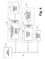
- FIGURE 4 illustrates a universal safety block as an expandable module, a standalone module, and a backplane module, in accordance with an aspect of the subject invention
- FIGURE 5 illustrates an industrial control system that includes a plurality of field I/O components that process safety and non-safety signals that communicate utilizing one or more industrial automation protocols, in accordance with an aspect of the subject invention
- FIGURE 6 illustrates a methodology that determines if data is related to safety or non-safety and processes such data accordingly, in accordance with an aspect of the subject invention
- FIGURE 7 illustrates a methodology that employs block and modular I/O components to process data related to safety or non-safety, in accordance with an aspect of the subject invention.
- FIGURE 1 illustrates a universal safety block (USB) 10 that can receive and/or transmit data related to safety and non-safety and process such data accordingly.
- the USB 10 includes a processing component 12 and safety I/O circuitry 14.
- the processing component 12 further includes a logic control component 16 and a safety data table 18.
- a standard message bridge 20 can be employed to transmit non-safety (e.g., standard) data to one or more control components.
- the processing component 12 can determine the type, format, source, etc. of data received and determine the appropriate method of processing such data based on one or more factors.
- the processing component 12 can be substantially any type of logic fabric such as an ASIC, a processor, a discrete logic device, etc.
- the processing component 12 can include a memory (not shown) to store, edit, manipulate and retrieve desired data.
- the logic control component 16 can be employed to determine if received data is related to safety or non-safety and communicate respective data to a predetermined recipient. Such a determination can be made based on information received with the data, format of the data, source of the data, etc.
- the logic control component 16 can communicate safety data to the safety data table 18.
- the safety data table 18 can interface with the safety I/O circuitry 14 to apply to one or more inputs and/or outputs.
- the safety data table 18 can update the one or more inputs and/or outputs every cycle, predetermined time increment, etc. via the safety I/O circuitry 14.
- the safety I/O circuitry 14 can be substantially any hardware and/or software interface wherein data can be transmitted to and/or from the USB 10.
- the safety I/O circuitry 14 can include one or more features in order to meet a particular safety standard.
- the safety I/O circuitry 14 utilizes redundant data paths to prevent a single point of failure.
- diagnostics are employed to maintain data integrity.
- the USB 10 can be employed in substantially any control environment (e.g., machine, process, safety. etc.) and communicate utilizing substantially any protocol and/or standard.
- the USB 10 can employ any number of media to transmit and/or receive data from one or more sources including a wide area network (WAN), a machine area network (MAN), a control area network (CAN), a large area network (LAN), a backplane, etc.
- WAN wide area network
- MAN machine area network
- CAN control area network
- LAN large area network
- backplane etc.
- the USB 10 can be employed in substantially any location within a control architecture such as a network interface, an expandable safety block, a stand alone safety block, a backplane module, etc.
- a network interface 22, a backplane interface 24 and a backplane extension 26 can be employed.
- the network interface 22 can consist of a plug, a receptacle, a screw terminal, etc. that can receive data from a network.
- the USB 10 can directly communicate with one or more networks.
- the backplane interface 24 can allow the USB 10 to communicate across a backplane to a network interface or other device.
- the backplane extension can allow the USB to communicate with one or more devices coupled to the USB 10 via a backplane.
- the USB 10 can utilize the network interface 22 to receive data from a network and the backplane expansion 24 to propagate received network data to one or more I/O components via a backplane.
- the USB 10 is employed as a standalone block, only the network interface is employed.
- a control system which includes a controller 52, the USB 10, an expansion port, and a modular non-safety I/O component (MNIC) 32.
- the USB 10 communicates with the controller 52 via the network 34.
- the USB 10 can communicate utilizing any number of protocols and/or standards.
- the USB 10 can communicate with an Ethernet/IP network.
- the USB 10 can communicate with a DeviceNet network.
- the USB 10 can communicate with an Ethernet/IP, a DeviceNet and a ControlNet network at substantially the same time.
- the controller 52 can include one of any number of processors, racks, modules, and/or various hardware and software that accept one or more inputs and allow processing such inputs. Various mathematical, Boolean, etc. functions can be performed on the input data and provide one or more outputs as a result.
- the controller 10 can include a memory (not shown) to store data values and/or algorithms for data processing for subsequent configuration and/or retrieval.
- the controller 52 can communicate utilizing any number of protocols.
- the controller 52 can employ one or more industrial automation protocols such as DeviceNet, ControlNet, Ethernet/IP, etc.
- the network 34 can consist of appropriate media.
- the network 34 is a hardwire connection from the controller 52 to the USB 10.
- the network 34 consists of wireless transmissions via wireless Ethernet, infrared, Bluetooth or other communication protocols.
- the controller 52 can utilize and execute various hardware, firmware and/or software to maintain compliance with one or more safety standards (e.g., IEC 61508) which define a maximum allowable probability of failure on demand.
- Internal hardware components (not shown) can be duplicative in order to meet various safety redundancy requirements.
- redundant microprocessors (not shown) can be employed to process substantially the same data at substantially the same time.
- firmware can be configured to provide redundant processing algorithms, etc. on data received. By providing such redundancy throughout a system, single point failures can be mitigated.
- receipt of a signal from a field component is not detected by the control network at a control device (e.g., USB 10, MNIC 32, expansion port 30, etc.) and a warning signal and/or message is sent to one or more processors (e.g., within the controller 52, the USB 10, the expansion port 30, etc.) to indicate such a defective condition.
- a defective condition can be determined based on data value, time interval in which data is received, missing information, etc.
- Monitoring for defective data can be conducted within one or more devices within the industrial control network. In one approach, data quality is monitored at the controller 52, the USB 10, the expansion port 30 and the MNIC 32. In this manner, defective data can be detected and located quickly so that such a condition can be remedied.
- the controller 52 can provide an appropriate response to one or more control devices (e.g., devices that control a process and/or machine that receive direction from the controller 52).
- the control device is a swinging robotic arm wherein the pre-determined safe state is an immediate "power off” condition.
- the control device is an exhaust fan wherein the pre-determined safe state is "power on” ensuring harmful substances cannot accumulate and, if present, are dispersed.
- the control network can be deterministic to monitor that all safety messages are transmitted in a predetermined and a predictable amount of time.
- Each device e.g., USB 10, MNIC 32, expansion port 30, etc.
- Each device within the control network can be customized to have its own periodic response time. From this, each device within the control network can have expectations of guaranteed message delivery.
- one or more safety messages include a timestamp, which is checked to insure that the one or more safety messages arrive within a predefined time expectation. Safety messages arriving beyond the time expectation can cause the affected connection and associated device(s) to go to its predetermined safe state.
- Devices on the control network can require a dual channel design for crosschecking of safety messages as they arrive.
- the network protocol can require that all safety data be transmitted twice; once normal and once with the data inverted. Because data redundancy is built into the network protocol, the dual channels will each pick up messages and cross check results to minimize inaccuracy.
- the network 34 can be a communication network with high integrity that operates correctly (with a relatively high degree of confidence) or goes to a pre-defined state.
- Standard networks achieve a probability of failure on demand that is sufficient for most control applications but insufficient for safety applications.
- a safety protocol employed on the network 34 can require specific added measures to ensure that safety data sent from one device reaches another device with a higher degree of integrity than a standard network. Whereas standard networking systems are built to tolerate a certain number of errors, safety systems trap errors. Verification of a network's integrity can be obtained by maintaining compliance with one or more third party standards (e.g., IEC 61508).
- the USB 10 receives communication sent from the controller 52 via the network 34.
- the USB 10 can include any number of various input and/or output terminals. Such data can include analog, digital, thermocouple, strain gauge, encoder signals and the like. In one example, the USB 10 includes 8 digital output terminals and 8 digital input terminals. In another example, the USB 10 includes 6 analog outputs and 2 thermocouple inputs. It is to be appreciated that the USB 10 can be employed to accept and/or output data in substantially any desired format and/or protocol.
- the expansion port 30 is employed to allow appending additional I/O points on the network 34.
- the expansion port 30 can contain hardware, firmware and/or software required to maintain compliance with one or more safety standards.
- the firmware regulates how data bridging is accomplished as it is transmitted from the USB 10 to the MNIC 32. Data bridging can regulate the way data is handled as it is transmitted from one device to another within the safety control network.
- the MNIC 32 receives data through the expansion port 14 and can include any number of input and/or output terminals which can process substantially any data type. Each terminal can communicate utilizing substantially any desired communication protocol and/or standard.
- the MNIC 32 can communicate across a backplane (not shown) wherein additional modular I/O components can be added as desired. Individual modular I/O components allow additional I/O to be added on an as needed basis such as when a machine and/or process is augmented and/or reconfigured. In this manner, unnecessary costs can be mitigated by avoiding the purchase of I/O components that are not required.
- the MNIC 32 and the USB 10 are interchanged on the network.
- the MNIC 32 is directly coupled to the network 34 and the expansion port 30 is employed to allow communication from the USB 10 to the network 34.
- the expansion port 30 is employed to allow communication from the USB 10 to the network 34.
- any number of additional modular I/O components can be added to the system.
- one or more expansion ports can be employed to allow additional block I/O components and/or modular I/O components to be added to the network.
- the USB 10 and/or expansion port 30 can be updated such that it can handle both safety and non-safety related data.
- network messages can be identified by the USB 10 as either a safety message or a non-safety message and handled accordingly. If a message is identified as a safety message, the message is routed to the safety data table 18 wherein the message is analyzed and processed by the USB 10. Alternatively, if a message is identified as a non-safety message, the message can be bridged to the MNIC 32 for processing.
- Such data handling can be in compliance with one or more safety standards (IEC 61508) and/or safety integrity levels (e.g., SIL 3, SIL 4, etc.). These standards can prohibit configuration and/or manipulation of safety data to insure that such data is not compromised as it is transmitted throughout the control network.
- the MNIC 32 accepts data from the network 34 via the USB 10 and processes one or more non-safety data packets.
- the MNIC 32 can include one or more modular devices wherein each device can contain one or more terminals that relate to any number of various data types.
- a modular device includes two digital outputs and two digital inputs.
- a modular device includes four analog outputs. It is to be appreciated that any number, type and combination of inputs and/or outputs are contemplated.
- a combination of safety and non-safety modular devices are employed. Additional modular devices can be added to the MNIC 32 as needed.
- the MNIC 32 and the USB 10 can be contained in any number form factors, housings, profiles and the like.
- the USB 10 and the MNIC 32 are contained in a form factor that substantially protects against dust and immersion in liquid between 15 centimeters and 1 meter (e.g., meeting IP 67 requirements).
- the MNIC 32 and the USB 10 are hermetically sealed to prevent contaminants and/or other particulate matter from disrupting operation of these I/O devices.
- the network can communicate utilizing any protocols, standards, etc.
- the network 34 communicates utilizing one or more industrial automation protocols such as DeviceNet, ControlNet and EtherNet/IP to seamlessly integrate I/O control, device configuration and data collection.
- industrial automation protocols to communicate safety data on one standard network can be a cost effective approach that reduces cabling, improves productivity and reduces safety hazards.
- Industrial automation protocols and/or networks can allow a user to view the control network from an office environment or any point in the system, drilling down to device level information on the plant floor and can provide seamless communication across networks. In this manner, a user can control, configure and collect data from across the enterprise.
- Utilizing one or more industrial automation protocols to communicate safety data can allow the combination of safety and non-safety data within a single control network.
- preexisting networks can be updated to process safety data alongside non-safety data in conformance with various safety standards.
- a user can combine safety and non-safety networks without having to invest in safety specific gateways and bridges, without additional programming languages and without additional training and maintenance associated with a new network or software.
- Such technology can utilize existing cables and build on programming and training already used, which can provide simpler installation and maintenance. This also enables users to upgrade their networks while both protecting their initial investment and maintaining existing functionality (e.g., non-safety data processing).
- One advantage of employing one or more industrial automation protocols to communicate on the control network is the ability to connect safety devices and standard devices on the same network or wire, either with or without the need for a safety controller.
- safety interlock switches can operate alongside variable speed drives, safety network monitors with light curtains, and safety programmable logic controllers with standard programmable logic controllers (PLCs). In this manner, the integrity of the safety control loop is not affected by any of the standard control devices regardless of the combination of devices that are employed.
- the safety aspects of a control architecture can be automated in the same manner as a standard control environment. Regardless of whether the safety and standard controls remain separate or are integrated, the user can apply the benefits gained from using DeviceNet on non-safety equipment to safety applications also, such as reduced engineering and installation costs, increased diagnostics and increased architectural flexibility.
- an industrial automation protocol e.g., DeviceNet, EtherNet/IP, etc.
- a safety loop can be constructed that does not require a controller.
- peer-to-peer communications can allow sensors to communicate directly with actuators or safety relays, with seamless bridging and routing that can allow safety relays on one segment of the control network to connect to safety mats or light curtains on another.
- end to end safety allows such a loop to be closed with standard, commercial switch and bridge technology.
- Complex sequential control of safety loops can similarly be effected utilizing safety controller technology with PLCs connected either to different industrial automation protocol segments (e.g., one EtherNet/IP and another DeviceNet), responding to presence sensing safety devices and controlling safety actuators on a local network segment, or on one or more remote segments utilizing an industrial automation protocol bridging and routing capabilities.
- segmentation of the network architecture into multiple DeviceNet safety segments allows time-critical safety loops to be optimized.
- Such scalable integration of multiple network segments can result in shorter loop closure times and therefore tighter safety exclusion zones.
- stand-alone cell-level industrial automation protocol (e.g., DeviceNet, EtherNet/IP, etc.) segments can be integrated on an EtherNet/IP backbone, enabling peer-to-peer communications across multiple cells.
- FIGURE 3 illustrates a control system wherein the USB 10 is employed as both a backplane module and a standalone safety block.
- a safety controller 52 communicates with a field I/O component 54 which includes the MNIC 32, the expansion port 30, and the USB 10.
- a bridging element 62 is communicates safety data to the USB 10 via the expansion port 30.
- the USB 10 is utilized as a backplane module.
- the USB 10 communicates directly to the safety controller 52 via a control network 60 as a standalone safety block.
- the MNIC 32 identifies received messages and processes them based on whether they are safety messages or standard messages. if a data is determined to be non-safety, it is ported to a standard data table for processing via the MNIC 32. If, however, the data is determined to be safety, this safety data is bridged via the bridging element 62 to and/or from the USB 10 for processing.
- the bridging element 62 can be employed to properly handle received and/or transmitted data and can include hardware, software and/or firmware to transmit data from the safety network 60 to the MNIC 32 and the USB 10 within the FIOC 54. In addition, firmware and/or software can be updated periodically to specify handling of particular data within the MNIC 32 and/or the USB 10.
- control system shows the network 60 connected to the modular non-safety I/O component 32 then connected to the USB 10, substantially any combination of control devices are contemplated.
- standard (e.g., non-safety) and safety I/O can be ordered as desired.
- two modular standard (e.g., non-safety) I/O components can be coupled to the MNIC 32.
- the USB 10 can be coupled to the first two modular standard I/O components and one or more standard I/O components (not shown) can be coupled to the four modular safety components.
- substantially any combination of safety and standard I/O modules and corresponding data types are contemplated.
- the MNIC 26 and the USB 10 can communicate with the control network (e.g., DeviceNet, ControlNet, etc.) 60 along a common backplane. Connection from the control network 60 to the backplane is facilitated via a network interface (not shown).
- This backplane can be included in the form factor of each of the I/O devices that communicate within the control system. In this manner, the backplane will be appended each time an additional modular I/O device and/or block I/O device is added to the system. Communication across the backplane to the USB 10 can be facilitated utilizing the backplane interface 24.
- the USB 10 can communicate with the control network 60 directly utilizing the network interface 22.
- the network interface 22 can be a plug-in receptacle that receives a DeviceNet safety network cable to interact with the USB 10 as a standalone safety block within a control architecture.
- the network interface 22 can consist of one or more screw terminals, sockets, etc. employed to provide an electrical connection from the USB 10 to the control network 60. It is to be appreciated that the foregoing is for illustrative purposes only and that the USB 10 can directly communicate with a network utilizing substantially any protocol and/or standard.
- the USB 10 can receive, process and transmit safety related data. Additional I/O modules can be appended to the USB 10 to provide a flexible control architecture. In one example, additional I/O modules are added to the standalone USB 10 to accommodate an additional control system. In another approach, a network interfaces provides direct communication wherein the standalone USB 10 is employed as a backplane module (e.g., as illustrated in FIOC 54).
- FIGURE 4 illustrates a control architecture wherein the USB 10 is employed in three different aspects of control I/O.
- the USB 10 is employed with the FIOC 54 as a backplane module.
- the USB 10 is employed within a FIOC 56 as an expandable safety block wherein one or more additional I/O modules can be coupled to the USB 10 for expanded I/O capability.
- the USB 10 is employed as a standalone safety block that can communicate directly with the control network 60.
- the USB 10 can communicate with one or more control devices and employed in any number of locations throughout a control architecture. Such flexibility can be facilitated via the network interface 22, the backplane interface 24 and the backplane extension 26. Thus, the network interface 22 can facilitate communication between the USB 10 and the control network 60. The USB 10 can also employ the network interface 22 and the backplane extension 26 to communicate with both the control network and the various I/O on a backplane at substantially the same time. The backplane interface can be employed to communicate with a backplane when the USB 10 is employed as a backplane module.
- FIGURE 5 illustrates a control network wherein the field I/O component (FIOC) 54 is coupled to the controller 52 and the modular safety I/O component 56 via a first communication protocol (e.g., DeviceNet, ControlNet, EtherNet/IP, etc.) network 72.
- a first communication protocol e.g., DeviceNet, ControlNet, EtherNet/IP, etc.
- a second FIOC 56 and a standalone USB 10 are coupled to the controller 52 via the first communication protocol.
- a third FIOC 74 is coupled to the controller 52 via a second communication protocol (e.g., DeviceNet, ControlNet, EtherNet/IP, etc.) network 76.
- a fourth FIOC 78 is coupled to the controller 52 via a third communication protocol (e.g., DeviceNet, ControlNet, EtherNet/IP, etc.) network 80.
- each of the three networks 72, 76 and 80 utilize a different protocol.
- the FlOCs 54, 56, 74 and 78 each include the MNIC 26, the bridging element 62, the expansion port 14, and the USB 10.
- the USB 10 can include any number of input and/or output terminals wherein each terminal can process any type and/or format of data.
- the MNIC 26 can include substantially any number of non-safety data in a variety of formats.
- the MNIC 32 can process the non-safety data received from each of the protocol networks 72, 76 and 80.
- the bridging element 62 ports safety data to the USB 10 for processing.
- the network interface can employ an artificial intelligence (AI) component (not shown) to determine the type of protocol received by the network interface.
- AI artificial intelligence
- the Al component can determine the appropriate processing of data within such protocol.
- the appropriate format and/or processing of received data can be determined by machine learning wherein one or more training sets of data with examples of desired results and/or undesired results for data format and/or processing techniques can be utilized to train the system.
- initial conditions based on one or more features that indicate desired results, can be utilized. Such initial conditions can be adjusted over time and in response to user actions associated with returned results in order to improve discrimination.
- the term "inference” refers generally to the process of reasoning about or inferring states of the system, environment, and/or user from a set of observations as captured via events and/or data. Inference can be employed to identify a specific context or action, or can generate a probability distribution over states, for example. Inference can refer to techniques employed for composing higher-level events from a set of events and/or data. Various classification schemes and/or systems (e.g., support vector machines, neural networks (e.g., back-propagation, feed forward back propagation, radial bases and fuzzy logic), expert systems, Bayesian networks, and data fusion) can be employed in connection with performing automatic and/or inferred action in connection with the subject invention.
- neural networks e.g., back-propagation, feed forward back propagation, radial bases and fuzzy logic
- expert systems e.g., Bayesian networks, and data fusion
- Industrial automation fieldbuses and associated protocols can enable control, configuration and data collection, and provides benefits such as: media independence; multiple data exchange options; seamless, multi-hop routing; and producer/consumer services.
- Typical applications for industrial automation fieldbuses e.g., protocol networks 72, 76 and 80
- protocol networks 72, 76 and 80 can include press control, robot weld cell control, transfer lines, packaging machines, burner management, emergency shut down and/or ski lifts, for example.
- industrial automation protocols can be readily integrated into existing standard plant-wide systems various manufacturing settings such as the automotive, semiconductor, entertainment and food and beverage industries.
- Industrial automation fieldbus networks can be based on implementation in existing networks and provide significant flexibility to the user in how safety solutions are implemented.
- One advantage is if a user initially installs a "safety only" architecture, the user can easily upgrade in the future to an integrated system network (e.g., safety and standard) by adding standard devices on the network. Such integration can be performed while maintaining integrity of the safety and non-safety data throughout the network.
- an integrated system network e.g., safety and standard
- EtherNet/IP One industrial automation protocol, the EtherNet/IP standard, allows various devices such as I/O and controls from multiple vendors to communicate over a network running an Ethernet protocol. Such an approach is in contrast with proprietary approaches where controllers running Ethernet protocols from a specific vendor can work only with that vendor's Ethernet I/O.
- EtherNet/IP allows interoperability between devices from different vendors since Ethernet only defines a physical media, a scheme for sharing the physical media, and a simple frame format and addressing method for moving data packets across a network.
- Upper-layer protocols that are not defined by Ethernet determine network functions and how devices communicate with each other on the one or more industrial automation protocol networks 72, 76 and 80. Upper-layer protocols must run on top of Ethernet and such upper-layer protocols can be employed by the EtherNet/IP protocol to provide standards employed in industrial settings.
- TCP/IP Transmission Control Protocol/Internet Protocol which provides services that let devices transfer messages to each other.
- TCP/IP does not guarantee that the devices know what to do with the messages they receive. Instead, an application-layer protocol can be utilized to let connected devices understand received messages.
- EtherNet/IP defines one of the few such layers. EtherNet/IP uses an approach called TCP/IP encapsulation to let messages for these protocols pass over an Ethernet network.
- a device running DeviceNet would encapsulate a DeviceNet message as the data portion of an Ethernet message. The message could then be processed and/or communicated by a chip running the data link layer of Ethernet.
- EtherNet/IP protocol networks also employ UDP/IP (User Datagram Protocol/IP) to allow multicasting via implicit messaging.
- Multicasting is typified by a source sending a message to a group of destinations (as compared to unicasting: sending a different message to each destination).
- Implicit messaging puts only real-time I/O information in a data field of the Ethernet message, but no protocol information.
- the purpose of multicasting is to minimize network traffic, and the purpose of implicit messaging is to minimize the time needed to process the message at the node receiving it. The benefit is that such messages can be short, involve little processing overhead, and promote time-critical performance needed for control.
- DeviceNet Another industrial automation protocol is DeviceNet which can allow devices to synchronize for precise system performance and can also be utilized with one or more safety systems. Such features include automatic checking for duplicate node addresses; built-in retries at the data-link layer; priorities established by configuration; bit error rate of approximately ⁇ 10 7 under stress (i.e., approximately one error transmitted every 150 years on a fully loaded system). DeviceNet also employs error counters for each connection to the network and utilizes connection based messaging so both producer and consumer can identify data failure. Also, standard DeviceNet media and topology requires no changes when used in safety implementations which means current DeviceNet users can continue to use existing wiring to implement a safety system by adding DeviceNet safety devices to the existing network, as can be true for other industrial automation protocols. In this manner, end users can integrate standard and safety controls on a single network. This feature can provide significant cost savings, as safety devices that are usually hardwired to a safety controller can now be directly connected on an existing DeviceNet, sharing the network with other safety and standard devices.
- the DeviceNet safety protocol ensures that standard devices do not interfere with the function of the safety devices and vice versa.
- manufacturers are required to run a separate network just for safety controls, which adds an unnecessary level of complexity to a system.
- a separate network not tightly integrated into the standard control system architecture often precludes systems from responding uniquely to each type of fault.
- a DeviceNet safety system supports both approaches by allowing any device to talk to any other safety point on the same segment or another segment in the network architecture.
- Input and output modules can have features such as "pulse test”, which verifies that the input or output circuit is functioning and not shorted, and "data echo,” which uses feedback to check that an output module has received and acted on a command.
- Advanced diagnostics can also check the external load to verify that voltage is applied to the actuator, and input or output modules have the capability to detect open or short-circuit wires and loss of power.
- Industrial automation protocols can automatically inherits the bridging and routing capabilities employed by users of EtherNet/IP, ControlNet and DeviceNet. Therefore, from a plant wide perspective, DeviceNet safety users benefit from a multi-link architecture.
- a single DeviceNet safety network can contain as many as 64 devices, but as DeviceNet safety is based on a seamless, multi-link architecture, the maximum device count is virtually unlimited.
- multiple DeviceNet safety segments can be interconnected using a high-speed EtherNet/IP backbone, with all the nodes communicating as seamless as if they are on the same segment.
- This feature allows original equipment manufacturers (OEMs) to design standalone machines each with its own separate subnet, ensuring that safety loops on one machine can be accessed but not negatively impacted by other machines. From an OEM's standpoint, the ability to ensure and take responsibility for a performance output, such as their machine's safety exclusion zone, is critical. An end user, meanwhile, also benefits because multiple machines can be cross-interlocked using an EtherNet/IP backbone without risking the set parameters or performance integrity of any individual machine.
- OEMs original equipment manufacturers
- IEC 61508 requires one of two approaches: physical separation of safety and standard control functionality or logical separation.
- DeviceNet safety supports both approaches but is optimized to enforce logical separation. This logical separation ensures safe operation and provides greater opportunities to improve productivity at a lower cost than implementing physical separation.
- a single controller platform can be used to enforce logical separation, which simplifies configuration of the safety system and reduces training. Further it enhances the overall safety of the system by minimizing the level of specialist expertise required to maintain the system.
- FIGURES 6 and 7 are shown and described as executing serially, it is to be understood and appreciated that the present invention is not limited by the illustrated order, as some aspects could, in accordance with the present invention, occur in different orders and/or concurrently with other aspects from that shown and described herein. Moreover, not all illustrated features may be required to implement a methodology in accordance with an aspect the present invention.
- FIGURE 6 illustrates a methodology to determine if received data is related to safety or non-safety and to process such data accordingly.
- data is received from a control network via a network interface.
- Received data can be transmitted through the network utilizing appropriate media such as CAT-5, coaxial, twisted pair, etc.
- data can be transmitted via one or more protocols such as DeviceNet, ControlNet, EtherNet/IP, etc.
- the network interface can be coupled to the control network via one or wired or wireless means.
- data can be received on a periodic basis, based on condition or on a continuous basis.
- one or more processing components determine if such data is related to safety or non-safety.
- the data is compared to a look up table of known safety data. If the received data matches data on the list, the data is deemed to be safety data.
- the safety table is coupled to an Al component (not shown) and an inference is made as to the type of data received (e.g., safety or non-safety) based on one or more factors. Such factors can include data value, data source, data format, associated metadata, overhead, etc.
- Data can be interfaced to the safety table as it is received or can be first accumulated in a memory (not shown) interface the safety table on a periodically.
- the standard data table can contain a listing of standard (e.g., non-safety) data and/or determine that such data is non-safety based on an inference, as noted above.
- data can be designated as non-safety by default after comparison to the safety table at 102.
- non-safety I/O component can be associated with any type of profile or form factor. Such form factor can additionally be designed to prevent the intrusion of dust and/or liquids in compliance with one or more standards (e.g., IP 67).
- the non-safety I/O component can be a block design wherein a plurality of predetermined I/O terminals are designated.
- the non-safety I/O component can be a modular design wherein I/O terminals are added to the control system as needed. It is to be appreciated that although a single non-safety I/O component is discussed, any number of non-safety I/O components are contemplated with substantially any profile and/or form factor design (e.g., block, modular, etc.).
- data is processed via the non-safety I/O component.
- data processing can involve analyzing and manipulating one or more parameters associated with the data.
- a data packet is opened and various parameters are extracted for use in the control system. For instance, various pieces of information such as a bit string associated with a particular control device, overhead error checking information, metadata and the like can be analyzed.
- the non-safety I/O component can perform any number of functions such as returning to an idle mode to await further instruction, processing other received data, etc.
- the safety I/O component can be in any form factor, design, layout or profile.
- the safety I/O component can be in a block design and/ or a modular design.
- substantially any number of terminals, data types, formats and the like can be employed.
- the data is processed via the safety I/O component. Processing such data can include determining the source of the data, the value of particular data strings, data format, associated security level, emergency level and the like. In this manner, the safety data can be analyzed to determine if an action needs to be taken. In one example, the action can be to place one or more data values into a safe state. Such safe state can be predetermined such as power off, power on, toggle data value, etc.
- FIGURE 7 illustrates a methodology of intermixing block and modular I/O components.
- signals can be mixed wherein both safety and non-safety signals are transmitted to the I/O components.
- a controller is interfaced to a universal safety block.
- the controller can be employed to receive, store and/or transmit data based on any number of factors.
- a memory can be associated with the controller for data and/or algorithm storage.
- a processor can be employed to execute one or more commands related to data manipulation and/or one or more additional processes and/or tasks.
- the controller can be configured to communicate utilizing a particular language or protocol.
- the controller can communicate on a DeviceNet network and be hardwired to the network interface.
- the controller can receive a plurality of process control data from various disparate control components in a particular architecture. For instance, data can be gathered from one or more drives, solenoids, sensors, measurement systems, thermocouples, encoders, etc.
- a modular non-safety I/O component is interfaced to the universal safety block via an expansion port.
- the modular non-safety I/O component can receive, store, process and/or output non-safety data transmitted from the expansion port.
- the expansion port is employed to allow one or more modular I/O components to be coupled to the block I/O component to provide flexible I/O capability for a control architecture. It is to be appreciated that any number of expansion ports can be employed to couple one or more block I/O components to one or more modular I/O components. Further, the I/O components can be employed specifically for all safety data, all non-safety data or any desired combination of safety and non-safety data.
- data is received from a control network via the network interface.
- data is sorted and processed based on whether the data is related to safety or non-safety.
- a safety control block interfaces to one or more devices utilizing one or more communication protocols wherein a network interface receives and/or transmits data directly from a network.
- a backplane interface receives and/or transmits data from a backplane.
- a backplane extension receives and/or transmits data from a backplane.
- a processing component receives data from at least one of the network interface, backplane interface and backplane extension and determines if the received data is related to safety or non-safety.
- a safety I/O circuitry receives safety data from the processing component; wherein the safety data is utilized to communicate to at least one control device.
Landscapes
- Physics & Mathematics (AREA)
- General Physics & Mathematics (AREA)
- Engineering & Computer Science (AREA)
- Automation & Control Theory (AREA)
- Small-Scale Networks (AREA)
- Communication Control (AREA)
- Multi Processors (AREA)
Applications Claiming Priority (2)
| Application Number | Priority Date | Filing Date | Title |
|---|---|---|---|
| US66332905P | 2005-03-18 | 2005-03-18 | |
| US11/240,706 US8055814B2 (en) | 2005-03-18 | 2005-09-30 | Universal safety I/O module |
Publications (2)
| Publication Number | Publication Date |
|---|---|
| EP1703346A2 true EP1703346A2 (fr) | 2006-09-20 |
| EP1703346A3 EP1703346A3 (fr) | 2007-08-29 |
Family
ID=36337633
Family Applications (1)
| Application Number | Title | Priority Date | Filing Date |
|---|---|---|---|
| EP06005406A Withdrawn EP1703346A3 (fr) | 2005-03-18 | 2006-03-16 | Module E/S de sécurité universel |
Country Status (4)
| Country | Link |
|---|---|
| US (1) | US8055814B2 (fr) |
| EP (1) | EP1703346A3 (fr) |
| CN (1) | CN1834838B (fr) |
| SG (1) | SG126081A1 (fr) |
Cited By (10)
| Publication number | Priority date | Publication date | Assignee | Title |
|---|---|---|---|---|
| EP1973017A3 (fr) * | 2007-03-22 | 2009-06-10 | Abb Ag | Automate programmable orienté vers la sécurité |
| DE102008013075A1 (de) * | 2008-03-06 | 2009-09-24 | Hilscher Gesellschaft für Systemautomation mbH | Speicherprogrammierbare Steuerung mit flexibler Kommunikations- und Steuerungsstruktur und Verfahren zu deren Konfiguration |
| DE102008029948A1 (de) | 2008-06-26 | 2010-01-21 | Phoenix Contact Gmbh & Co. Kg | Überwachungssystem |
| EP2315088A1 (fr) * | 2009-10-23 | 2011-04-27 | Sick Ag | Commande de sécurité |
| DE102009054155A1 (de) | 2009-11-23 | 2011-05-26 | Abb Ag | Ein- und/oder Ausgabe-Sicherheitsmodul für ein Automatisierungsgerät |
| CN102692891A (zh) * | 2012-05-31 | 2012-09-26 | 山西联华伟业科技有限公司 | 一种基于多种通信总线的可编程控制器 |
| WO2013076173A1 (fr) * | 2011-11-22 | 2013-05-30 | Hms Industrial Networks Ab | Système de sécurité |
| EP3051370A1 (fr) * | 2011-07-08 | 2016-08-03 | Rockwell Automation Technologies, Inc. | Commande industrielle à l'aide d'un panier à haute disponibilité |
| EP3267270A1 (fr) * | 2016-07-05 | 2018-01-10 | Siemens Aktiengesellschaft | Systeme d'automatisation a securite intrinseque |
| CN114788231A (zh) * | 2019-12-11 | 2022-07-22 | 菲尼克斯电气开发及制造股份有限公司 | 具有唯一网络地址的i/o网络模块 |
Families Citing this family (41)
| Publication number | Priority date | Publication date | Assignee | Title |
|---|---|---|---|---|
| US7917247B2 (en) * | 2005-04-21 | 2011-03-29 | Edward Kachnic | Auxiliary communication interface system and method thereof |
| US7660638B2 (en) * | 2005-09-30 | 2010-02-09 | Rockwell Automation Technologies, Inc. | Business process execution engine |
| EP1835699A1 (fr) * | 2006-03-17 | 2007-09-19 | ABB PATENT GmbH | Contrôleur de robot |
| US20070286181A1 (en) * | 2006-05-25 | 2007-12-13 | Dennis Bushmitch | Remote home/office monitoring and control using Skype |
| US8856522B2 (en) * | 2007-02-27 | 2014-10-07 | Rockwell Automation Technologies | Security, safety, and redundancy employing controller engine instances |
| US7764169B2 (en) * | 2008-03-12 | 2010-07-27 | Eaton Corporation | System for monitoring a plurality of sensors |
| JP5348499B2 (ja) * | 2009-03-12 | 2013-11-20 | オムロン株式会社 | I/oユニット並びに産業用コントローラ |
| US8307715B2 (en) * | 2009-03-24 | 2012-11-13 | Direct Measurments, Inc. | Directly applied read and transmit—digital strain encoder and digital load cell |
| DE102009019087A1 (de) * | 2009-04-20 | 2010-11-11 | Pilz Gmbh & Co. Kg | Sicherheitssteuerung und Verfahren zum Steuern einer automatisierten Anlage |
| BRPI0901450A2 (pt) * | 2009-05-04 | 2011-01-18 | Weg Automacao S A | módulo interface de protocolo de comunicação |
| DE102009022389A1 (de) * | 2009-05-22 | 2010-12-02 | Phoenix Contact Gmbh & Co. Kg | Steuerungssystem zum Steuern eines Prozesses |
| DE102009026124A1 (de) * | 2009-07-07 | 2011-01-13 | Elan Schaltelemente Gmbh & Co. Kg | Verfahren und System zur Erfassung, Übertragung und Auswertung sicherheitsgerichteter Signale |
| EP2317410B1 (fr) * | 2009-10-23 | 2012-01-04 | Sick Ag | Commande de sécurité |
| US9024486B2 (en) * | 2010-08-20 | 2015-05-05 | Rockwell Automation Technologies, Inc. | Adaptable automation control module with integrated power bus distributor |
| US8862425B2 (en) | 2010-12-09 | 2014-10-14 | Toyota Motor Engineering & Manufacturing North America, Inc. | Failure sensing and control system for cycle testing |
| CN102035679B (zh) * | 2010-12-17 | 2013-01-30 | 天津理工大学 | 基于EtherNet/IP协议的具有短路保护自诊断功能的远程I/O模块 |
| DE102012009494B4 (de) * | 2012-05-14 | 2017-04-13 | Balluff Gmbh | Steuereinrichtung zum Steuern eines Sicherheitsgerätes |
| US9513617B2 (en) * | 2012-10-03 | 2016-12-06 | Rockwell Automation Technologies, Inc. | Industrial control system with position offsets embedded in remote devices |
| US9435654B2 (en) * | 2013-06-01 | 2016-09-06 | Savari, Inc. | System and method for creating, storing, and updating local dynamic MAP database with safety attribute |
| DE102014109956B4 (de) * | 2013-07-17 | 2020-09-10 | Infineon Technologies Ag | Sensor mit Schnittstelle für Funktionssicherheit |
| US9863786B2 (en) | 2013-07-17 | 2018-01-09 | Infineon Technologies Ag | Sensor with interface for functional safety |
| US9559804B2 (en) * | 2013-10-07 | 2017-01-31 | Savari, Inc. | Connected vehicles adaptive security signing and verification methodology and node filtering |
| GB2522469B (en) | 2014-01-27 | 2017-10-11 | Nidec Control Techniques Ltd | Servo drive device |
| US9563180B2 (en) * | 2014-02-28 | 2017-02-07 | Rockwell Automation Technologies, Inc. | Configuration-enabled motor drive safety |
| US9582376B2 (en) | 2014-11-14 | 2017-02-28 | Invensys Systems, Inc. | Unified communications module (UCM) |
| US10031502B2 (en) | 2015-03-27 | 2018-07-24 | Rockwell Automation Germany Gmbh & Co. Kg | I/O expansion for safety controller |
| US9897990B2 (en) * | 2015-05-04 | 2018-02-20 | Rockwell Automation Germany Gmbh & Co. Kg | Safety controller with rapid backup and configuration |
| US10514683B2 (en) | 2015-09-16 | 2019-12-24 | Profire Energy, Inc. | Distributed networking system and method to implement a safety state environment |
| US10432754B2 (en) | 2015-09-16 | 2019-10-01 | Profire Energy, Inc | Safety networking protocol and method |
| CN106607935B (zh) * | 2015-10-22 | 2018-12-14 | 沈阳新松机器人自动化股份有限公司 | 一种双机器人协同工作急停处理系统 |
| US10197985B2 (en) | 2015-10-29 | 2019-02-05 | Rockwell Automation Germany Gmbh & Co. Kg | Safety controller module |
| US9768572B1 (en) | 2016-04-29 | 2017-09-19 | Banner Engineering Corp. | Quick-connector conversion system for safety controller |
| EP3388904B1 (fr) * | 2017-04-13 | 2023-03-15 | duagon AG | Architecture multic ur, carte d'interface et procédé de traitement de paquets de données |
| US11029660B2 (en) * | 2017-05-15 | 2021-06-08 | Rockwell Automation Asia Pacific Business Center, Pte. Ltd. | Safety input system for monitoring a sensor in an industrial automation system |
| CN112424713A (zh) * | 2018-08-23 | 2021-02-26 | 西门子股份公司 | 人工智能计算设备、控制方法及装置、工程师站及工业自动化系统 |
| EP3712721A1 (fr) * | 2019-03-19 | 2020-09-23 | Siemens Aktiengesellschaft | Messages de diagnostic importants du point de vue de la sécurité |
| CN110554978B (zh) * | 2019-08-30 | 2022-02-15 | 北京交大思诺科技股份有限公司 | 一种采用通用i/o模块实现的安全计算机平台 |
| DE112020006666B4 (de) * | 2020-07-30 | 2025-01-30 | Mitsubishi Electric Corporation | Numerische Steuerung und numerisches Steuerungssystem |
| US12298729B2 (en) * | 2022-03-07 | 2025-05-13 | Rockwell Automation Technologies, Inc. | Systems and methods for gating local control signals |
| DE102022120198A1 (de) * | 2022-08-10 | 2024-02-15 | Pilz Gmbh & Co. Kg | Modulare Steuerungseinrichtung |
| IT202200026709A1 (it) * | 2022-12-23 | 2024-06-23 | Pizzato Elettrica Srl | Apparecchiatura per connettere dispositivi industriali ad una rete dati e relativo sistema di comunicazione |
Family Cites Families (24)
| Publication number | Priority date | Publication date | Assignee | Title |
|---|---|---|---|---|
| US5764927A (en) * | 1995-09-29 | 1998-06-09 | Allen Bradley Company, Inc. | Backplane data transfer technique for industrial automation controllers |
| US6999824B2 (en) * | 1997-08-21 | 2006-02-14 | Fieldbus Foundation | System and method for implementing safety instrumented systems in a fieldbus architecture |
| EP1043640A2 (fr) | 1999-04-09 | 2000-10-11 | Siemens Aktiengesellschaft | Système d'automatisation à sécurité intrinsèque avec un processeur standard et méthode pour un système d'automatisation à sécurité intrinsèque |
| DE19928517C2 (de) * | 1999-06-22 | 2001-09-06 | Pilz Gmbh & Co | Steuerungssystem zum Steuern von sicherheitskritischen Prozessen |
| DE19939567B4 (de) * | 1999-08-20 | 2007-07-19 | Pilz Gmbh & Co. Kg | Vorrichtung zum Steuern von sicherheitskritischen Prozessen |
| US6516041B1 (en) * | 1999-10-07 | 2003-02-04 | Westinghouse Electric Co. Llc | Method and apparatus to eliminate confirmation switches and channel demultiplexer from soft control man-machine interface (MMI) |
| US6721900B1 (en) * | 1999-12-22 | 2004-04-13 | Rockwell Automation Technologies, Inc. | Safety network for industrial controller having reduced bandwidth requirements |
| US6909923B2 (en) * | 1999-12-22 | 2005-06-21 | Rockwell Automation Technologies, Inc. | Safety communication on a single backplane |
| WO2002019957A2 (fr) * | 2000-09-05 | 2002-03-14 | Storz-Endoskop Gmbh | Systeme et procede de commande centrale de dispositifs utilises lors d'une operation |
| JP3997988B2 (ja) * | 2001-05-31 | 2007-10-24 | オムロン株式会社 | 安全ユニット及びコントローラシステム並びにコントローラの連結方法及びコントローラシステムの制御方法 |
| CN1222138C (zh) | 2001-05-31 | 2005-10-05 | 欧姆龙株式会社 | 安全网络系统、安全从动设备、安全控制器、通信方法、安全网络系统中的信息收集方法及监视方法 |
| EP1404061B1 (fr) * | 2001-06-22 | 2011-08-10 | Omron Corporation | Systeme de reseau securise et esclave securise |
| EP2256562B1 (fr) * | 2001-06-22 | 2012-01-25 | Omron Corporation | Contrôleur de sécurité |
| US6549034B1 (en) * | 2001-12-27 | 2003-04-15 | Rockwell Automation Technologies, Inc. | Programmable logic controller for safety systems with reduced cross-wiring |
| US20040059844A1 (en) * | 2002-09-20 | 2004-03-25 | Woodhead Industries, Inc. | Network active I/O module with removable memory unit |
| SE0203819D0 (sv) * | 2002-12-19 | 2002-12-19 | Abb As | Method to increase the safety integrity level of a control system |
| US7366774B2 (en) * | 2003-01-31 | 2008-04-29 | Rockwell Automation Technologies, Inc. | Network delay monitor for safety control networks |
| DE10317131A1 (de) * | 2003-04-14 | 2004-10-28 | Siemens Ag | Verfahren zur Datenübertragung von sicherheitsrelevanten Informationen |
| CN1802612B (zh) | 2003-04-17 | 2010-12-01 | 菲尔德巴士基金 | 用于在面向块的安全相关开放控制系统中操作的装置 |
| JP4212970B2 (ja) | 2003-06-30 | 2009-01-21 | 株式会社キーエンス | 安全リレーシステム |
| DE10330916A1 (de) | 2003-07-04 | 2005-02-03 | Pilz Gmbh & Co. Kg | Vorrichtung und Verfahren zum automatisierten Steuern eines Betriebsablaufs bei einer technischen Anlage |
| US7213168B2 (en) * | 2003-09-16 | 2007-05-01 | Rockwell Automation Technologies, Inc. | Safety controller providing for execution of standard and safety control programs |
| US7149655B2 (en) * | 2004-06-18 | 2006-12-12 | General Electric Company | Methods and apparatus for safety controls in industrial processes |
| US7970540B2 (en) * | 2004-11-08 | 2011-06-28 | Toyota Motor Engineering & Manufacturing North America, Inc. | System and method of vehicular wireless communication using an integrated coordinating access point |
-
2005
- 2005-09-30 US US11/240,706 patent/US8055814B2/en active Active
-
2006
- 2006-03-16 EP EP06005406A patent/EP1703346A3/fr not_active Withdrawn
- 2006-03-16 SG SG200601729A patent/SG126081A1/en unknown
- 2006-03-17 CN CN200610067974.7A patent/CN1834838B/zh not_active Expired - Fee Related
Cited By (17)
| Publication number | Priority date | Publication date | Assignee | Title |
|---|---|---|---|---|
| EP1973017A3 (fr) * | 2007-03-22 | 2009-06-10 | Abb Ag | Automate programmable orienté vers la sécurité |
| DE102008013075A1 (de) * | 2008-03-06 | 2009-09-24 | Hilscher Gesellschaft für Systemautomation mbH | Speicherprogrammierbare Steuerung mit flexibler Kommunikations- und Steuerungsstruktur und Verfahren zu deren Konfiguration |
| DE102008029948A1 (de) | 2008-06-26 | 2010-01-21 | Phoenix Contact Gmbh & Co. Kg | Überwachungssystem |
| DE102008029948B4 (de) | 2008-06-26 | 2018-08-30 | Phoenix Contact Gmbh & Co. Kg | Überwachungssystem |
| US8744805B2 (en) | 2008-06-26 | 2014-06-03 | Phoenix Contact Gmbh & Co. Kg | Monitoring system |
| EP2315088A1 (fr) * | 2009-10-23 | 2011-04-27 | Sick Ag | Commande de sécurité |
| DE102009054155A1 (de) | 2009-11-23 | 2011-05-26 | Abb Ag | Ein- und/oder Ausgabe-Sicherheitsmodul für ein Automatisierungsgerät |
| WO2011060872A2 (fr) | 2009-11-23 | 2011-05-26 | Abb Ag | Module de sécurité pour un appareil d'automatisation |
| WO2011060872A3 (fr) * | 2009-11-23 | 2011-07-14 | Abb Ag | Module de sécurité pour un appareil d'automatisation |
| US9104190B2 (en) | 2009-11-23 | 2015-08-11 | Abb Ag | Safety module for an automation device |
| EP3051370A1 (fr) * | 2011-07-08 | 2016-08-03 | Rockwell Automation Technologies, Inc. | Commande industrielle à l'aide d'un panier à haute disponibilité |
| WO2013076173A1 (fr) * | 2011-11-22 | 2013-05-30 | Hms Industrial Networks Ab | Système de sécurité |
| CN102692891A (zh) * | 2012-05-31 | 2012-09-26 | 山西联华伟业科技有限公司 | 一种基于多种通信总线的可编程控制器 |
| EP3267270A1 (fr) * | 2016-07-05 | 2018-01-10 | Siemens Aktiengesellschaft | Systeme d'automatisation a securite intrinseque |
| CN107577163A (zh) * | 2016-07-05 | 2018-01-12 | 西门子公司 | 防故障的自动化系统、输入系统和设备 |
| US10712724B2 (en) | 2016-07-05 | 2020-07-14 | Siemens Aktiengesellschaft | Failsafe automation system |
| CN114788231A (zh) * | 2019-12-11 | 2022-07-22 | 菲尼克斯电气开发及制造股份有限公司 | 具有唯一网络地址的i/o网络模块 |
Also Published As
| Publication number | Publication date |
|---|---|
| CN1834838A (zh) | 2006-09-20 |
| SG126081A1 (en) | 2006-10-30 |
| EP1703346A3 (fr) | 2007-08-29 |
| CN1834838B (zh) | 2011-01-19 |
| US20060224811A1 (en) | 2006-10-05 |
| US8055814B2 (en) | 2011-11-08 |
Similar Documents
| Publication | Publication Date | Title |
|---|---|---|
| US8055814B2 (en) | Universal safety I/O module | |
| US11500363B2 (en) | Discrete manufacturing hybrid cloud solution architecture | |
| US8509927B2 (en) | Control system for controlling safety-critical processes | |
| EP2783495B1 (fr) | Systeme de securite | |
| US20200220846A1 (en) | Automation and/or Communications Appliance and Method for Checking Datagrams Transmitted in An Industrial Automation System | |
| CN115208967B (zh) | 用于连接网络中的并行冗余协议的方法和系统 | |
| US11860609B2 (en) | Single Pair Ethernet for operator control stations | |
| US10938967B2 (en) | Method and apparatus for communication in a motor drive application | |
| CN102739641B (zh) | 用于自动化网络的入口保护器 | |
| CN103034162B (zh) | 用于控制可编程控制器的通信输入的计算机执行的方法 | |
| EP4149063B1 (fr) | Procédé et appareil pour un trajet de communication alternatif pour réseaux connectés | |
| AU2023200276B2 (en) | Modular control network architecture | |
| EP3952245B1 (fr) | Adressage de dispositifs dans les réseaux de contrôle industriel | |
| AU2023202410B2 (en) | Apparatus and method for identifying device communication failures in communication networks | |
| PAUL | INDUSTRIAL NETWORKING STANDARDS FOR IMPROVED COMMUNICATION AND CONTROL | |
| CN119996528A (zh) | 用于连接网络中的四路径并行冗余协议的方法和系统 | |
| Alam | Physical Layer Fault Tolerance for Foundation Fieldbus Network |
Legal Events
| Date | Code | Title | Description |
|---|---|---|---|
| PUAI | Public reference made under article 153(3) epc to a published international application that has entered the european phase |
Free format text: ORIGINAL CODE: 0009012 |
|
| AK | Designated contracting states |
Kind code of ref document: A2 Designated state(s): AT BE BG CH CY CZ DE DK EE ES FI FR GB GR HU IE IS IT LI LT LU LV MC NL PL PT RO SE SI SK TR |
|
| AX | Request for extension of the european patent |
Extension state: AL BA HR MK YU |
|
| RIC1 | Information provided on ipc code assigned before grant |
Ipc: G05B 19/05 20060101ALI20070424BHEP Ipc: F16P 3/00 20060101ALI20070424BHEP Ipc: G05B 19/042 20060101AFI20070424BHEP |
|
| PUAL | Search report despatched |
Free format text: ORIGINAL CODE: 0009013 |
|
| AK | Designated contracting states |
Kind code of ref document: A3 Designated state(s): AT BE BG CH CY CZ DE DK EE ES FI FR GB GR HU IE IS IT LI LT LU LV MC NL PL PT RO SE SI SK TR |
|
| AX | Request for extension of the european patent |
Extension state: AL BA HR MK YU |
|
| 17P | Request for examination filed |
Effective date: 20071220 |
|
| 17Q | First examination report despatched |
Effective date: 20080128 |
|
| AKX | Designation fees paid |
Designated state(s): DE FR GB IT |
|
| STAA | Information on the status of an ep patent application or granted ep patent |
Free format text: STATUS: THE APPLICATION IS DEEMED TO BE WITHDRAWN |
|
| 18D | Application deemed to be withdrawn |
Effective date: 20100120 |