EP3267270A1 - Systeme d'automatisation a securite intrinseque - Google Patents
Systeme d'automatisation a securite intrinseque Download PDFInfo
- Publication number
- EP3267270A1 EP3267270A1 EP16177938.4A EP16177938A EP3267270A1 EP 3267270 A1 EP3267270 A1 EP 3267270A1 EP 16177938 A EP16177938 A EP 16177938A EP 3267270 A1 EP3267270 A1 EP 3267270A1
- Authority
- EP
- European Patent Office
- Prior art keywords
- fail
- safe
- automation system
- assigned
- processor
- Prior art date
- Legal status (The legal status is an assumption and is not a legal conclusion. Google has not performed a legal analysis and makes no representation as to the accuracy of the status listed.)
- Granted
Links
Images


Classifications
-
- G—PHYSICS
- G05—CONTROLLING; REGULATING
- G05B—CONTROL OR REGULATING SYSTEMS IN GENERAL; FUNCTIONAL ELEMENTS OF SUCH SYSTEMS; MONITORING OR TESTING ARRANGEMENTS FOR SUCH SYSTEMS OR ELEMENTS
- G05B19/00—Program-control systems
- G05B19/02—Program-control systems electric
- G05B19/04—Program control other than numerical control, i.e. in sequence controllers or logic controllers
- G05B19/042—Program control other than numerical control, i.e. in sequence controllers or logic controllers using digital processors
- G05B19/0428—Safety, monitoring
-
- G—PHYSICS
- G05—CONTROLLING; REGULATING
- G05B—CONTROL OR REGULATING SYSTEMS IN GENERAL; FUNCTIONAL ELEMENTS OF SUCH SYSTEMS; MONITORING OR TESTING ARRANGEMENTS FOR SUCH SYSTEMS OR ELEMENTS
- G05B19/00—Program-control systems
- G05B19/02—Program-control systems electric
- G05B19/04—Program control other than numerical control, i.e. in sequence controllers or logic controllers
- G05B19/05—Programmable logic controllers, e.g. simulating logic interconnections of signals according to ladder diagrams or function charts
- G05B19/058—Safety, monitoring
-
- G—PHYSICS
- G05—CONTROLLING; REGULATING
- G05B—CONTROL OR REGULATING SYSTEMS IN GENERAL; FUNCTIONAL ELEMENTS OF SUCH SYSTEMS; MONITORING OR TESTING ARRANGEMENTS FOR SUCH SYSTEMS OR ELEMENTS
- G05B2219/00—Program-control systems
- G05B2219/10—Plc systems
- G05B2219/14—Plc safety
- G05B2219/14007—Plc as standalone for safety control of machine
Definitions
- the invention relates to a failsafe automation system according to the preamble of claim 1. Furthermore, the invention relates to an input system for a fail-safe automation system. In addition, the invention relates to a system.
- Fail-safe automation systems are used to control and / or regulate drives in safety-related areas such as industrial plants.
- automation systems use, by way of example, secure input methods, redundant (i.e., multiple) execution of individual elements of the automation system, and / or the secure transmission of signals between the individual elements.
- EP 2 192 461 A1 describes a control device and a system for fail-safe data transmission.
- the object is achieved by a fail-safe automation system according to claim 1.
- the object is further achieved by an input system according to claim 10 and by a system according to claim 11.
- the fail-safe automation system has a motion controller and at least one fail-safe processor.
- the fail-safe automation system has optional drives.
- the fail-safe automation system is used to control and / or regulate a plurality of drives.
- For the control and / or regulation of the drives is preferably the motion control.
- the drives are each assigned to an area, wherein the respective area is assigned in each case a security level and wherein the areas in each case adjacent to each other, in particular spatially adjacent, are arranged.
- the fail-safe processor may be implemented as a separate hardware component.
- the fail-safe processor can also be integrated in the motion control and / or in the drive.
- the fail-safe processor is preferably designed as a software module or as an additional computer program.
- An automation system is understood to mean at least a part of a drive system.
- the automation system advantageously includes components such as a motion controller, in particular an S PEICHER P rogrammierbare S controller (PLC), optionally processors, such as switching elements or network adapter (proxies, hosts) and optionally actuators on.
- the drives each have a power converter and a motor.
- a fail-safe automation system advantageously has a fail-safe motion control and / or fail-safe processors, wherein the fail-safe processors check, for example, the transmission of signals from the motion control to the drives.
- An automation system advantageously has a data connection for the transmission of data and / or signals.
- the plant is designed in particular as a production machine, machine tool or industrial plant, wherein the Plant has a fail-safe automation system described here.
- the drives are advantageously connected to the motion control.
- the drives have a power converter or a frequency converter and an electrical machine, in particular an (electric) motor on.
- a drive may include a brake and / or an encoder.
- the brake is preferably used for faster deceleration of the drive and / or to ensure the stoppage of the drive.
- a brake shortens the action time of the respective drive.
- the encoder is preferably used to verify the movement of the drive. Both the brake and the encoder can be connected to the motion control.
- a security level can be understood as meaning that a drive comes to a standstill within a predetermined time (action time) from its respective movement speed. The higher the security level, the lower the predetermined action time until the drive comes to a standstill. For an increase in the security level, moreover, a mechanical and / or electronic brake can be used.
- a certain level of security may be specified in accordance with legal requirements.
- the security level is particularly high.
- a fail-safe automation system is understood to mean an automation system which has one or more of the above-mentioned features of fail-safety.
- a fail-safe automation system or a fail-safe drive system can each also be characterized by a maximum speed of the respective drive.
- a fail-safe automation system may additionally or alternatively be distinguished by a defined reaction to an (incoming) signal. For example, it may be specified that opening a cover for a signal is only possible after a defined period of time.
- a security level is understood here to mean that the respective drive, which is assigned to the security level, is assigned a time duration, in particular a (re-) action time.
- the specified period of time is the time at which the drive reaches standstill at the latest.
- the fixed period of time may also be the period of time after which no more torque originates from the respective drive.
- the fixed period of time is also referred to here as the action time.
- a fail-safe processor can be understood as a module which supports or ensures secure transmission of data between the motion controller and the respective drive. Therefore, a fail-safe processor is preferably also designed as a communication module.
- a fail-safe processor is a fail-safe proxy block. Fail-safe means that a fail-safe interaction of several blocks can take place in an otherwise non-failsafe environment.
- the space in which the drives are located is divided into a plurality of areas.
- the areas are spatially adjacent and optionally substantially contiguous.
- a room is in particular an area of a production hall.
- the room has, by way of example, a first area, a second area and a third area.
- the first area may have the actual plant or production machine, in particular a press.
- the first area is assigned, for example, a first, eg low, security level.
- the second area extends around the plant by way of example.
- the second area are advantageously devices for equipping the system. If necessary, manual activities may be necessary here. Therefore, to protect the persons in the second area, a higher level of security may be necessary.
- the second area may adjoin the third area.
- the third area can be characterized by regular manual activities. Therefore, in this third area, a high level of security is necessary.
- the room is divided into the three areas, with each area having its own security level.
- the areas are each adjacent to each other in space, that is, the two areas each have a common boundary or are at least close to each other.
- the areas may also be separated by physical boundaries such as access locks, room dividers, corridors or (light) curtains.
- a security level can be assigned to the respective drive which is located in the respective area.
- the assignment can be made regardless of the connection of the respective drive to the motion control.
- the above object is achieved in such a way that the configuration can be configured flexibly by assigning the respective drive to the area or a security level.
- one area is assigned a fail-safe processor in each case.
- the fail-safe processor monitors the function of the respective drive in the assigned area.
- the fail-safe processor is connected to the motion control.
- the fail-safe processor ensures data exchange and / or signal exchange between the motion controller and the corresponding drive.
- the respective fail-safe processor is advantageously assigned to the respectively corresponding area.
- a fail-safe processor can be connected to the motion control.
- a fail-safe processor is assigned to each area.
- the respective security level can be ensured by a respective adapted fail-safe processor.
- one area can also be assigned a number of fail-safe processors.
- the respective drive and / or the respective fail-safe processor are connected via a fail-safe data connection.
- a fail-safe data connection is understood to be a data connection in which it is ensured that the correct signals or the correct data arrive at the intended time with the signal strength provided. Furthermore, the transmission of the correct data can be checked, in particular by a redundant design. A fail-safe transmission can be formed, for example, by a redundant transmission with subsequent comparison.
- fail-safe data connection An example of a fail-safe data connection is PROFIBUS or PROFINET from Siemens AG. Another fail-safe data connection is made by way of example using PROFIsafe addressing.
- connection of the individual components advantageously satisfies the chosen security standard.
- errors in the transmission of signals or data are revealed.
- the fail-safe automation system of the respective security level is assigned an action time, wherein the action time is a period of time from a trigger signal to the action of the respective drive.
- An action time is an example of the length of time that a switch needs to change a switching state.
- the monitoring time can also be composed of several switching times and / or braking times.
- the respective fail-safe processor is designed as fail-safe IO controller (input / output controller).
- the fail-safe processor is used in particular to avoid errors in the transmission of data and / or signals.
- a fail-safe processor is therefore advantageously designed as an IO controller (input-output controller or input / output controller), in particular for a so-called I-device communication, for example for a further processor or a further component.
- IO controller input-output controller or input / output controller
- a non-fail-safe component can become a fail-safe component.
- the fail-safe processor can also be designed as a so-called I-slave, in particular for a so-called I-slave communication for a processor, in particular a non-failsafe processor, or a corresponding component be.
- a non-failsafe processor is also called a standard processor.
- the latter embodiment can also be combined with fail-safe components, in particular further fail-safe processors.
- the fail-safe processor can also be provided for data transmission and / or signal transmission from and to a (further) fail-safe processor. This is also referred to as I slave to a direct data exchange and / or signal exchange.
- the fail-safe processor can also be provided as an IO controller with a (further) fail-safe processor, in particular for fail-safe transmission of signals and / or data. This is also known as shared-device functionality.
- a non-failsafe automation system can be upgraded to a fail-safe automation system at least in certain areas.
- the fail-safe processors are each connected to each other by a data connection.
- the fail-safe processors are interconnected.
- a fail-safe data connection is used to connect the fail-safe processors.
- the corresponding safety standard for example by redirecting the communication or a controlled shutdown of the machine, can be adhered to.
- Fail-safe processors are preferably designed as software modules. A connection of the fail-safe processors is then carried out by a data exchange of the software modules.
- connection of the fail-safe processors with each other is preferably used for redundancy in multiple fail-safe processors.
- a fail-safe processor in slave mode can forward data and / or signals to a fail-safe processor in master mode.
- the (direct) connection of the fail-safe processors serves for the rapid exchange of data.
- the drives and / or the fail-safe processors are each assigned to a zone.
- the zone is formed as one level each in a network or other connection scheme of the data connection. Different zones may each have different security unit levels.
- a zone can be understood as a fail-safe zone.
- drives that do not have special safety requirements can be assigned to a first zone.
- the first zone can therefore be characterized by a low to no security level. In the first zone, therefore, only one simple fail-safe processor is assigned. If necessary, no fail-safe processor is necessary.
- a network is understood here as the connection diagram of the individual components of the automation system.
- a network can also have a second and / or a third zone with higher security standards. Due to the increased security requirement, a higher level of error safety is necessary.
- An improved fail-safe transmission of data and / or signals in the zones of the network, which ensures a fail-safe communication in the network, can be ensured by further fail-safe processors, which are assigned to the respective zone of the network.
- the data transmission and / or signal transmission can be adapted to the requirements of the error safety of the individual drive.
- the respective fail-safe processor, the respective motion controller and / or the respective drive are of redundant design.
- a redundant design of a component such as a motion controller, a (fail-safe) processor or a (fail-safe) data connection means that the fail-safe automation system has the respective component multiple times.
- two components for example two fail-safe processors, interact with one another in such a way that, in a normal operation, the first component is designed as a master and performs corresponding functions and the second component is designed as a slave and performs corresponding functions. If a malfunction is detected in the first fail-safe processor, the second fail-safe processor (previously in the slave function) takes the place of the first fail-safe processor. The second fail-safe processor may continue to operate in the master function while the first fail-safe processor is placed in a slave function.
- the data and / or the signals are routed via the at least two data connections.
- an adjustment of the transmitted data or signals takes place.
- a data comparison or a signal comparison between the individual components of the automation system takes place via the data connection.
- this also has an input system, wherein the input system is provided for providing signals for the fail-safe automation system, wherein the input system is configured to assign the respective security level for the respective drive.
- the input system is advantageously designed analogously to an engineering system.
- the input system preferably serves for interaction with the user, wherein the user can specify motion sequences for the individual drives.
- the user can also assign the security level, the respective fail-safe processor and / or the respective monitoring time to the respective drive or another component.
- the input advantageously takes place with the aid of an input means.
- the input system may be integrated in an advantageous embodiment in a control program or interact with the control program data technology.
- the input system is designed as a computer program or as a computer program package.
- the input system can therefore be installed on a computer and executed on the computer.
- the input system is transferred to the main memory and executed with a processor of the arithmetic unit.
- the input system and / or the control program are advantageously used to provide data to the motion control and / or to the (fail-safe) processors or drives.
- the input system is also advantageous for specifying the zone of the network in which the fail-safe processor, the respective drive and / or the respective motion control are located.
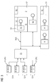
- FIG. 1 shows a fail-safe automation system.
- the fail-safe automation system has a motion controller BS, wherein the motion controller BS is connected to drives A1, A2, A3.
- the connection of the movement control BS with the respective drive A1, A2, A3 is carried out with a data connection BUS, wherein the data connection BUS is advantageously designed as fail-safe data connection BUS.
- the drives A1, A2, A3 are each assigned to a range S1, S2, S3.
- a first drive A1 is assigned to a first area S1.
- a second drive A2 is assigned to a second area S2 and a third drive A3 is assigned to a third area S3.
- the respective area S1, S2, S3 is assigned to a fail-safe processor F-CPU.
- the fail-safe processor F-CPU serves to monitor the respective area S1, S2, S3.
- the fail-safe processors F-CPU can also be used in motion control BS and / or integrated into the respective drive A1, A2, A3.
- FIG. 2 shows another fail-safe automation system.
- the motion controller BS is connected to a drive A1, A2, A3 via a connection An1, An2, An3.
- the data connection BUS is advantageously designed as a fail-safe data connection BUS.
- fail-safe processors F-CPU are connected to the motion controller BS.
- the connection of the fail-safe processors F-CPU and the motion control BS advantageously also takes place with the aid of a data connection BUS, wherein the data connection BUS is designed in particular as (industrial) Ethernet.
- the fail-safe processors F-CPU can be provided for error protection of the respective connection An1, An2, An3 of the motion control BS.
- FIG. 3 shows another fail-safe automation system.
- a motion controller BS is designed to control drives A1, A2, A3.
- the data connection BUS is advantageously designed as a fail-safe data connection BUS.
- the drives A1, A2, A3 are arranged in areas S1, S2, S3 of a room, in particular a production hall or a system.
- the individual drives each include a motor M.
- the respective area S1, S2, S3 is assigned a security level F1, F2, F3.
- the individual areas are optionally separated from each other by boundaries such as light barriers, access doors in connection with partitions (not shown).
- the security level F1, F2, F3 indicates how failsafe the respective drive A1, A2, A3 must be formed or must work.
- the error safety of the individual drive A1, A2, A3 and / or the respective area S1, S2, S3 is indicated by an action time t1, t2, t3.
- the action time t1, t2, t3 serves to determine how fast a drive A1, A2, A3 must be decelerated to a standstill or to a rated speed.
- two first drives A1 are assigned to a first area S1, wherein the first area S1 is assigned to a first security level F1.
- the first area S1 is formed with the highest security level F1.
- the movement control BS further serves to drive a second drive A2, wherein the second drive A2 is assigned to a second area S2 or is located in this.
- the second area S2 is assigned a second security level F2.
- the security level F2 is less than the first security level F1.
- the second monitoring time t2 is advantageously made larger than the first monitoring time t1.
- the motion controller BS further serves to drive a third drive A3, wherein the third drive A3 is associated with a third area S3.
- the third area S3 is assigned to a third security level F3.
- the third area S3 is characterized by a third action time period t3, wherein the action time t3 can be greater than the second monitoring time t2 and can be formed to be greater than the first monitoring time t1.
- the security level F1, F2, F3 is based on the monitoring time t1, t2, t3, wherein a short monitoring time t1, t2, t3 characterizes a high security level F1, F2, F3.
- fail-safe processors F-CPU are assigned to the respective security levels F1, F2, F3 or to the individual areas S1, S2, S3.
- the fail-safe processors F-CPU are advantageously designed as fail-safe HOST modules.
- the safety relevance of the first area S1 is the highest.
- the first fail-safe processor F-CPU is redundant.
- the fail-safe processors F-CPU are designed as fail-safe host modules F-HOST. Numbering 1, 2 and 3 under the corresponding reference numbers (F-HOST) merely indicates that the redundant fail-safe processor may be the same host model. The other two host modules can be configured differently.
- FIG. 4 shows an input system.
- the input system has an input mask EM, the input mask EM listing the individual drives A1, A2, A3 and schematically representing their respective connection to the motion control BS.
- the input mask has the respective security level F1, F2 for the respective drive A1, A2, A3.
- a respective security level F1, F2 can be assigned to the respective area S1, S2, S3.
- the respective drive A1, A2, A3 can likewise be assigned a respective action time t1, t2, t3.
- the input mask is used to enter the security levels F1, F2 or the areas S1, S3 to the individual drives A1, A2, A3.
- the inputted data is transferred from the input system to the movement controller BS, whereby also the movement control BS can advantageously intervene on the basis of the relations entered in the input mask.
- FIG. 5 shows zones Z1, Z2, Z3 of a network of a fail-safe automation system.
- the zones Z1, Z2, Z3 are formed as network levels, wherein a first network level comprises the motion control, the second network environment or the second zone Z2, at least one failsafe processor and a third zone or a third network level the respective drives A1, A2, A3.
- a data connection BUS to connect the individual levels is advantageously a data connection BUS.
- Individual zones Z1, Z2, Z3 can also be distinguished and / or connected by fail-safe data links BUS.
- one aspect of the invention relates to a fail-safe automation system.
- Another aspect of the invention relates to an input system.
- a motion controller BS is connected to a plurality of fail-safe processors F-CPU.
- the fail-safe processors F-CPU are each assigned to a security level S1, S2, S3.
- the motion controller BS is assigned at least one drive A1, A2, A3, wherein the respective drives A1, A2, A3 are respectively assigned to areas S1, S2, S3 and the respective area S1, S2, S3 is assigned a security level F1, F2, F3 ,
- the security level F1, F2, F3 indicates how (error-) sure the respective area S1, S2, S3 must be formed. Due to the fail-safe automation system, individual areas S1, S2, S3 in rooms such as production halls can easily be equipped with the necessary fault tolerance.
Landscapes
- Physics & Mathematics (AREA)
- General Physics & Mathematics (AREA)
- Engineering & Computer Science (AREA)
- Automation & Control Theory (AREA)
- Safety Devices In Control Systems (AREA)
Priority Applications (3)
| Application Number | Priority Date | Filing Date | Title |
|---|---|---|---|
| EP16177938.4A EP3267270B1 (fr) | 2016-07-05 | 2016-07-05 | Systeme d'automatisation a securite intrinseque |
| US15/637,803 US10712724B2 (en) | 2016-07-05 | 2017-06-29 | Failsafe automation system |
| CN201710525165.4A CN107577163B (zh) | 2016-07-05 | 2017-06-30 | 防故障的自动化系统、输入系统和设备 |
Applications Claiming Priority (1)
| Application Number | Priority Date | Filing Date | Title |
|---|---|---|---|
| EP16177938.4A EP3267270B1 (fr) | 2016-07-05 | 2016-07-05 | Systeme d'automatisation a securite intrinseque |
Publications (2)
| Publication Number | Publication Date |
|---|---|
| EP3267270A1 true EP3267270A1 (fr) | 2018-01-10 |
| EP3267270B1 EP3267270B1 (fr) | 2022-01-19 |
Family
ID=56360253
Family Applications (1)
| Application Number | Title | Priority Date | Filing Date |
|---|---|---|---|
| EP16177938.4A Not-in-force EP3267270B1 (fr) | 2016-07-05 | 2016-07-05 | Systeme d'automatisation a securite intrinseque |
Country Status (3)
| Country | Link |
|---|---|
| US (1) | US10712724B2 (fr) |
| EP (1) | EP3267270B1 (fr) |
| CN (1) | CN107577163B (fr) |
Families Citing this family (1)
| Publication number | Priority date | Publication date | Assignee | Title |
|---|---|---|---|---|
| CN115629531B (zh) * | 2022-11-14 | 2026-04-07 | 江苏科技大学 | 一种支持容错机制的造波机控制系统及控制方法 |
Citations (5)
| Publication number | Priority date | Publication date | Assignee | Title |
|---|---|---|---|---|
| EP1703346A2 (fr) * | 2005-03-18 | 2006-09-20 | Rockwell Automation Technologies, Inc. | Module E/S de sécurité universel |
| DE102007028390A1 (de) * | 2007-06-15 | 2008-12-18 | Abb Research Ltd. | Prozesssteuerung, System und Verfahren zur automatisierten Anpassung von Prozessparametern wenigstens einer Handhabungsvorrichtung |
| EP2192461A1 (fr) | 2008-12-01 | 2010-06-02 | Siemens Aktiengesellschaft | Dispositif de commande et système de transmission de données sécurisée contre les erreurs |
| DE102009054157B3 (de) * | 2009-11-23 | 2011-04-28 | Abb Ag | Steuerungssystem zum Steuern von sicherheitskritischen und nichtsicherheitskritischen Prozessen |
| EP2395274A1 (fr) * | 2010-06-08 | 2011-12-14 | Rockwell Automation Technologies, Inc. | Zones de sécurité dynamiquement adaptables |
Family Cites Families (7)
| Publication number | Priority date | Publication date | Assignee | Title |
|---|---|---|---|---|
| US7302676B2 (en) * | 2000-08-07 | 2007-11-27 | Siemens Aktiengesselschaft | Method for debugging flowchart programs for industrial controllers |
| WO2003024031A1 (fr) * | 2001-09-10 | 2003-03-20 | Nokia Corporation | Procede de transmission d'informations d'ordonnancement a duree critique entre des dispositifs reseau individuels dans un reseau hertzien, par des liaisons point a point a creneaux de temps |
| DE10206903A1 (de) * | 2002-02-19 | 2003-09-04 | Siemens Ag | Softwareapplikation, Softwarearchitektur und Verfahren zur Erstellung von Softwareapplikationen, insbesondere für MES-Systeme |
| US9116531B2 (en) * | 2013-02-27 | 2015-08-25 | General Electric Company | Methods and systems for current output mode configuration of universal input-output modules |
| DE102013104265A1 (de) | 2013-04-26 | 2014-10-30 | Pilz Gmbh & Co. Kg | Vorrichtung und Verfahren zum Absichern einer automatisiert arbeitenden Maschine |
| KR101883086B1 (ko) * | 2014-04-24 | 2018-07-27 | 미쓰비시덴키 가부시키가이샤 | Plc 유닛 및 프로그래머블 로직 컨트롤러 |
| US9632492B2 (en) * | 2015-01-23 | 2017-04-25 | Rockwell Automation Asia Pacific Business Ctr. Pte., Ltd. | Redundant watchdog method and system utilizing safety partner controller |
-
2016
- 2016-07-05 EP EP16177938.4A patent/EP3267270B1/fr not_active Not-in-force
-
2017
- 2017-06-29 US US15/637,803 patent/US10712724B2/en not_active Expired - Fee Related
- 2017-06-30 CN CN201710525165.4A patent/CN107577163B/zh not_active Expired - Fee Related
Patent Citations (5)
| Publication number | Priority date | Publication date | Assignee | Title |
|---|---|---|---|---|
| EP1703346A2 (fr) * | 2005-03-18 | 2006-09-20 | Rockwell Automation Technologies, Inc. | Module E/S de sécurité universel |
| DE102007028390A1 (de) * | 2007-06-15 | 2008-12-18 | Abb Research Ltd. | Prozesssteuerung, System und Verfahren zur automatisierten Anpassung von Prozessparametern wenigstens einer Handhabungsvorrichtung |
| EP2192461A1 (fr) | 2008-12-01 | 2010-06-02 | Siemens Aktiengesellschaft | Dispositif de commande et système de transmission de données sécurisée contre les erreurs |
| DE102009054157B3 (de) * | 2009-11-23 | 2011-04-28 | Abb Ag | Steuerungssystem zum Steuern von sicherheitskritischen und nichtsicherheitskritischen Prozessen |
| EP2395274A1 (fr) * | 2010-06-08 | 2011-12-14 | Rockwell Automation Technologies, Inc. | Zones de sécurité dynamiquement adaptables |
Also Published As
| Publication number | Publication date |
|---|---|
| US20180011470A1 (en) | 2018-01-11 |
| US10712724B2 (en) | 2020-07-14 |
| EP3267270B1 (fr) | 2022-01-19 |
| CN107577163A (zh) | 2018-01-12 |
| CN107577163B (zh) | 2021-04-09 |
Similar Documents
| Publication | Publication Date | Title |
|---|---|---|
| DE102009042368B4 (de) | Steuerungssystem zum Steuern von sicherheitskritischen Prozessen | |
| EP0875810B1 (fr) | Méthode et dispositif de surveillance d'une installation comprenant plusieurs unités fonctionnelles | |
| EP2422243B1 (fr) | Commande de sécurité pour commander une installation automatisée et procédé de génération d'un programme d'application pour une commande de sécurité | |
| EP2315088B1 (fr) | Commande de sécurité | |
| EP3098673B1 (fr) | Procede et dispositif de validation automatique de fonctions de securite sur un systeme de securite construit de façon modulaire | |
| EP1642179B1 (fr) | Dispositif pour commander de maniere automatisee le deroulement d'une operation dans une installation technique | |
| EP3100121B1 (fr) | Procédé et dispositif pour déconnecter en toute sécurité une charge électrique | |
| EP1054309B1 (fr) | Procédé et appareil pour la transmission sûre de données par l'intermédiaire d'un système de bus | |
| EP1589386B1 (fr) | Système de commande de processus | |
| EP3420426B1 (fr) | Dispositif et procede d'adaptation d'une commande numerique sur une machine a commander | |
| EP2099164B1 (fr) | Dispositif de sécurité destiné à la commande sécurisée d'actionneurs raccordés | |
| EP2098928A1 (fr) | Procédé et dispositif adaptés à la programmation et/ou la configuration d'un contrôleur de sécurité | |
| EP2835699B1 (fr) | Dispositif et procédé de configuration et/ou de programmation d'un contrôleur de sécurité | |
| EP3082002B1 (fr) | Commande de securite et procede de commande d'une installation automatisee | |
| EP1769293B1 (fr) | Systeme d'automatisation et module d'entrees/sorties pour ce systeme | |
| EP1969435B1 (fr) | Dispositif pour commander au moins une machine | |
| EP3267270B1 (fr) | Systeme d'automatisation a securite intrinseque | |
| DE102008038131A1 (de) | Redundantes Steuerungssystem und Verfahren zur sicherheitsgerichteten Ansteuerung von Aktoren | |
| EP1353246B1 (fr) | Dispositif de commutation de sécurité | |
| EP1327922B1 (fr) | Arrangement avec un interrupteur de sécurité | |
| EP2312408B1 (fr) | Commande de sécurité modulaire | |
| DE102004061013A1 (de) | Sichere Eingabe-/Ausgabe-Baugruppe für eine Steuerung | |
| DE102019109753A1 (de) | Industrieanlage | |
| DE102010038484A1 (de) | Verfahren und Vorrichtung zum Steuern einer Anlage | |
| EP1455251A1 (fr) | Commutateur de sécurité configurable |
Legal Events
| Date | Code | Title | Description |
|---|---|---|---|
| PUAI | Public reference made under article 153(3) epc to a published international application that has entered the european phase |
Free format text: ORIGINAL CODE: 0009012 |
|
| STAA | Information on the status of an ep patent application or granted ep patent |
Free format text: STATUS: THE APPLICATION HAS BEEN PUBLISHED |
|
| AK | Designated contracting states |
Kind code of ref document: A1 Designated state(s): AL AT BE BG CH CY CZ DE DK EE ES FI FR GB GR HR HU IE IS IT LI LT LU LV MC MK MT NL NO PL PT RO RS SE SI SK SM TR |
|
| AX | Request for extension of the european patent |
Extension state: BA ME |
|
| STAA | Information on the status of an ep patent application or granted ep patent |
Free format text: STATUS: REQUEST FOR EXAMINATION WAS MADE |
|
| 17P | Request for examination filed |
Effective date: 20180705 |
|
| RBV | Designated contracting states (corrected) |
Designated state(s): AL AT BE BG CH CY CZ DE DK EE ES FI FR GB GR HR HU IE IS IT LI LT LU LV MC MK MT NL NO PL PT RO RS SE SI SK SM TR |
|
| STAA | Information on the status of an ep patent application or granted ep patent |
Free format text: STATUS: EXAMINATION IS IN PROGRESS |
|
| 17Q | First examination report despatched |
Effective date: 20200325 |
|
| GRAP | Despatch of communication of intention to grant a patent |
Free format text: ORIGINAL CODE: EPIDOSNIGR1 |
|
| STAA | Information on the status of an ep patent application or granted ep patent |
Free format text: STATUS: GRANT OF PATENT IS INTENDED |
|
| INTG | Intention to grant announced |
Effective date: 20210914 |
|
| GRAS | Grant fee paid |
Free format text: ORIGINAL CODE: EPIDOSNIGR3 |
|
| GRAA | (expected) grant |
Free format text: ORIGINAL CODE: 0009210 |
|
| STAA | Information on the status of an ep patent application or granted ep patent |
Free format text: STATUS: THE PATENT HAS BEEN GRANTED |
|
| AK | Designated contracting states |
Kind code of ref document: B1 Designated state(s): AL AT BE BG CH CY CZ DE DK EE ES FI FR GB GR HR HU IE IS IT LI LT LU LV MC MK MT NL NO PL PT RO RS SE SI SK SM TR |
|
| REG | Reference to a national code |
Ref country code: GB Ref legal event code: FG4D Free format text: NOT ENGLISH |
|
| REG | Reference to a national code |
Ref country code: CH Ref legal event code: EP |
|
| REG | Reference to a national code |
Ref country code: DE Ref legal event code: R096 Ref document number: 502016014416 Country of ref document: DE |
|
| REG | Reference to a national code |
Ref country code: AT Ref legal event code: REF Ref document number: 1464152 Country of ref document: AT Kind code of ref document: T Effective date: 20220215 |
|
| REG | Reference to a national code |
Ref country code: IE Ref legal event code: FG4D Free format text: LANGUAGE OF EP DOCUMENT: GERMAN |
|
| REG | Reference to a national code |
Ref country code: LT Ref legal event code: MG9D |
|
| REG | Reference to a national code |
Ref country code: NL Ref legal event code: MP Effective date: 20220119 |
|
| PG25 | Lapsed in a contracting state [announced via postgrant information from national office to epo] |
Ref country code: NL Free format text: LAPSE BECAUSE OF FAILURE TO SUBMIT A TRANSLATION OF THE DESCRIPTION OR TO PAY THE FEE WITHIN THE PRESCRIBED TIME-LIMIT Effective date: 20220119 |
|
| PG25 | Lapsed in a contracting state [announced via postgrant information from national office to epo] |
Ref country code: SE Free format text: LAPSE BECAUSE OF FAILURE TO SUBMIT A TRANSLATION OF THE DESCRIPTION OR TO PAY THE FEE WITHIN THE PRESCRIBED TIME-LIMIT Effective date: 20220119 Ref country code: RS Free format text: LAPSE BECAUSE OF FAILURE TO SUBMIT A TRANSLATION OF THE DESCRIPTION OR TO PAY THE FEE WITHIN THE PRESCRIBED TIME-LIMIT Effective date: 20220119 Ref country code: PT Free format text: LAPSE BECAUSE OF FAILURE TO SUBMIT A TRANSLATION OF THE DESCRIPTION OR TO PAY THE FEE WITHIN THE PRESCRIBED TIME-LIMIT Effective date: 20220519 Ref country code: NO Free format text: LAPSE BECAUSE OF FAILURE TO SUBMIT A TRANSLATION OF THE DESCRIPTION OR TO PAY THE FEE WITHIN THE PRESCRIBED TIME-LIMIT Effective date: 20220419 Ref country code: LT Free format text: LAPSE BECAUSE OF FAILURE TO SUBMIT A TRANSLATION OF THE DESCRIPTION OR TO PAY THE FEE WITHIN THE PRESCRIBED TIME-LIMIT Effective date: 20220119 Ref country code: HR Free format text: LAPSE BECAUSE OF FAILURE TO SUBMIT A TRANSLATION OF THE DESCRIPTION OR TO PAY THE FEE WITHIN THE PRESCRIBED TIME-LIMIT Effective date: 20220119 Ref country code: ES Free format text: LAPSE BECAUSE OF FAILURE TO SUBMIT A TRANSLATION OF THE DESCRIPTION OR TO PAY THE FEE WITHIN THE PRESCRIBED TIME-LIMIT Effective date: 20220119 Ref country code: BG Free format text: LAPSE BECAUSE OF FAILURE TO SUBMIT A TRANSLATION OF THE DESCRIPTION OR TO PAY THE FEE WITHIN THE PRESCRIBED TIME-LIMIT Effective date: 20220419 |
|
| PG25 | Lapsed in a contracting state [announced via postgrant information from national office to epo] |
Ref country code: PL Free format text: LAPSE BECAUSE OF FAILURE TO SUBMIT A TRANSLATION OF THE DESCRIPTION OR TO PAY THE FEE WITHIN THE PRESCRIBED TIME-LIMIT Effective date: 20220119 Ref country code: LV Free format text: LAPSE BECAUSE OF FAILURE TO SUBMIT A TRANSLATION OF THE DESCRIPTION OR TO PAY THE FEE WITHIN THE PRESCRIBED TIME-LIMIT Effective date: 20220119 Ref country code: GR Free format text: LAPSE BECAUSE OF FAILURE TO SUBMIT A TRANSLATION OF THE DESCRIPTION OR TO PAY THE FEE WITHIN THE PRESCRIBED TIME-LIMIT Effective date: 20220420 Ref country code: FI Free format text: LAPSE BECAUSE OF FAILURE TO SUBMIT A TRANSLATION OF THE DESCRIPTION OR TO PAY THE FEE WITHIN THE PRESCRIBED TIME-LIMIT Effective date: 20220119 |
|
| PG25 | Lapsed in a contracting state [announced via postgrant information from national office to epo] |
Ref country code: IS Free format text: LAPSE BECAUSE OF FAILURE TO SUBMIT A TRANSLATION OF THE DESCRIPTION OR TO PAY THE FEE WITHIN THE PRESCRIBED TIME-LIMIT Effective date: 20220519 |
|
| REG | Reference to a national code |
Ref country code: DE Ref legal event code: R097 Ref document number: 502016014416 Country of ref document: DE |
|
| PG25 | Lapsed in a contracting state [announced via postgrant information from national office to epo] |
Ref country code: SM Free format text: LAPSE BECAUSE OF FAILURE TO SUBMIT A TRANSLATION OF THE DESCRIPTION OR TO PAY THE FEE WITHIN THE PRESCRIBED TIME-LIMIT Effective date: 20220119 Ref country code: SK Free format text: LAPSE BECAUSE OF FAILURE TO SUBMIT A TRANSLATION OF THE DESCRIPTION OR TO PAY THE FEE WITHIN THE PRESCRIBED TIME-LIMIT Effective date: 20220119 Ref country code: RO Free format text: LAPSE BECAUSE OF FAILURE TO SUBMIT A TRANSLATION OF THE DESCRIPTION OR TO PAY THE FEE WITHIN THE PRESCRIBED TIME-LIMIT Effective date: 20220119 Ref country code: EE Free format text: LAPSE BECAUSE OF FAILURE TO SUBMIT A TRANSLATION OF THE DESCRIPTION OR TO PAY THE FEE WITHIN THE PRESCRIBED TIME-LIMIT Effective date: 20220119 Ref country code: DK Free format text: LAPSE BECAUSE OF FAILURE TO SUBMIT A TRANSLATION OF THE DESCRIPTION OR TO PAY THE FEE WITHIN THE PRESCRIBED TIME-LIMIT Effective date: 20220119 Ref country code: CZ Free format text: LAPSE BECAUSE OF FAILURE TO SUBMIT A TRANSLATION OF THE DESCRIPTION OR TO PAY THE FEE WITHIN THE PRESCRIBED TIME-LIMIT Effective date: 20220119 |
|
| PGFP | Annual fee paid to national office [announced via postgrant information from national office to epo] |
Ref country code: IT Payment date: 20220720 Year of fee payment: 7 Ref country code: DE Payment date: 20220620 Year of fee payment: 7 |
|
| PLBE | No opposition filed within time limit |
Free format text: ORIGINAL CODE: 0009261 |
|
| STAA | Information on the status of an ep patent application or granted ep patent |
Free format text: STATUS: NO OPPOSITION FILED WITHIN TIME LIMIT |
|
| PG25 | Lapsed in a contracting state [announced via postgrant information from national office to epo] |
Ref country code: AL Free format text: LAPSE BECAUSE OF FAILURE TO SUBMIT A TRANSLATION OF THE DESCRIPTION OR TO PAY THE FEE WITHIN THE PRESCRIBED TIME-LIMIT Effective date: 20220119 |
|
| 26N | No opposition filed |
Effective date: 20221020 |
|
| PG25 | Lapsed in a contracting state [announced via postgrant information from national office to epo] |
Ref country code: SI Free format text: LAPSE BECAUSE OF FAILURE TO SUBMIT A TRANSLATION OF THE DESCRIPTION OR TO PAY THE FEE WITHIN THE PRESCRIBED TIME-LIMIT Effective date: 20220119 Ref country code: MC Free format text: LAPSE BECAUSE OF FAILURE TO SUBMIT A TRANSLATION OF THE DESCRIPTION OR TO PAY THE FEE WITHIN THE PRESCRIBED TIME-LIMIT Effective date: 20220119 |
|
| REG | Reference to a national code |
Ref country code: CH Ref legal event code: PL |
|
| GBPC | Gb: european patent ceased through non-payment of renewal fee |
Effective date: 20220705 |
|
| REG | Reference to a national code |
Ref country code: BE Ref legal event code: MM Effective date: 20220731 |
|
| PG25 | Lapsed in a contracting state [announced via postgrant information from national office to epo] |
Ref country code: LU Free format text: LAPSE BECAUSE OF NON-PAYMENT OF DUE FEES Effective date: 20220705 Ref country code: LI Free format text: LAPSE BECAUSE OF NON-PAYMENT OF DUE FEES Effective date: 20220731 Ref country code: FR Free format text: LAPSE BECAUSE OF NON-PAYMENT OF DUE FEES Effective date: 20220731 Ref country code: CH Free format text: LAPSE BECAUSE OF NON-PAYMENT OF DUE FEES Effective date: 20220731 |
|
| PG25 | Lapsed in a contracting state [announced via postgrant information from national office to epo] |
Ref country code: GB Free format text: LAPSE BECAUSE OF NON-PAYMENT OF DUE FEES Effective date: 20220705 Ref country code: BE Free format text: LAPSE BECAUSE OF NON-PAYMENT OF DUE FEES Effective date: 20220731 |
|
| PG25 | Lapsed in a contracting state [announced via postgrant information from national office to epo] |
Ref country code: IE Free format text: LAPSE BECAUSE OF NON-PAYMENT OF DUE FEES Effective date: 20220705 |
|
| REG | Reference to a national code |
Ref country code: AT Ref legal event code: MM01 Ref document number: 1464152 Country of ref document: AT Kind code of ref document: T Effective date: 20220705 |
|
| PG25 | Lapsed in a contracting state [announced via postgrant information from national office to epo] |
Ref country code: AT Free format text: LAPSE BECAUSE OF NON-PAYMENT OF DUE FEES Effective date: 20220705 |
|
| REG | Reference to a national code |
Ref country code: DE Ref legal event code: R119 Ref document number: 502016014416 Country of ref document: DE |
|
| PG25 | Lapsed in a contracting state [announced via postgrant information from national office to epo] |
Ref country code: HU Free format text: LAPSE BECAUSE OF FAILURE TO SUBMIT A TRANSLATION OF THE DESCRIPTION OR TO PAY THE FEE WITHIN THE PRESCRIBED TIME-LIMIT; INVALID AB INITIO Effective date: 20160705 |
|
| PG25 | Lapsed in a contracting state [announced via postgrant information from national office to epo] |
Ref country code: MK Free format text: LAPSE BECAUSE OF FAILURE TO SUBMIT A TRANSLATION OF THE DESCRIPTION OR TO PAY THE FEE WITHIN THE PRESCRIBED TIME-LIMIT Effective date: 20220119 Ref country code: DE Free format text: LAPSE BECAUSE OF NON-PAYMENT OF DUE FEES Effective date: 20240201 Ref country code: CY Free format text: LAPSE BECAUSE OF FAILURE TO SUBMIT A TRANSLATION OF THE DESCRIPTION OR TO PAY THE FEE WITHIN THE PRESCRIBED TIME-LIMIT Effective date: 20220119 |
|
| PG25 | Lapsed in a contracting state [announced via postgrant information from national office to epo] |
Ref country code: TR Free format text: LAPSE BECAUSE OF FAILURE TO SUBMIT A TRANSLATION OF THE DESCRIPTION OR TO PAY THE FEE WITHIN THE PRESCRIBED TIME-LIMIT Effective date: 20220119 |
|
| PG25 | Lapsed in a contracting state [announced via postgrant information from national office to epo] |
Ref country code: IT Free format text: LAPSE BECAUSE OF NON-PAYMENT OF DUE FEES Effective date: 20230705 |
|
| PG25 | Lapsed in a contracting state [announced via postgrant information from national office to epo] |
Ref country code: MT Free format text: LAPSE BECAUSE OF FAILURE TO SUBMIT A TRANSLATION OF THE DESCRIPTION OR TO PAY THE FEE WITHIN THE PRESCRIBED TIME-LIMIT Effective date: 20220119 |