EP1703766A2 - Haut-parleur de type à réflexion des basses et appareil d'affichage d'image - Google Patents
Haut-parleur de type à réflexion des basses et appareil d'affichage d'image Download PDFInfo
- Publication number
- EP1703766A2 EP1703766A2 EP06251220A EP06251220A EP1703766A2 EP 1703766 A2 EP1703766 A2 EP 1703766A2 EP 06251220 A EP06251220 A EP 06251220A EP 06251220 A EP06251220 A EP 06251220A EP 1703766 A2 EP1703766 A2 EP 1703766A2
- Authority
- EP
- European Patent Office
- Prior art keywords
- loudspeaker
- duct
- route
- box
- bass reflex
- Prior art date
- Legal status (The legal status is an assumption and is not a legal conclusion. Google has not performed a legal analysis and makes no representation as to the accuracy of the status listed.)
- Withdrawn
Links
Images






Classifications
-
- F—MECHANICAL ENGINEERING; LIGHTING; HEATING; WEAPONS; BLASTING
- F16—ENGINEERING ELEMENTS AND UNITS; GENERAL MEASURES FOR PRODUCING AND MAINTAINING EFFECTIVE FUNCTIONING OF MACHINES OR INSTALLATIONS; THERMAL INSULATION IN GENERAL
- F16H—GEARING
- F16H25/00—Gearings comprising primarily only cams, cam-followers and screw-and-nut mechanisms
- F16H25/18—Gearings comprising primarily only cams, cam-followers and screw-and-nut mechanisms for conveying or interconverting oscillating or reciprocating motions
- F16H25/20—Screw mechanisms
- F16H25/24—Elements essential to such mechanisms, e.g. screws, nuts
- F16H25/2454—Brakes; Rotational locks
-
- H—ELECTRICITY
- H04—ELECTRIC COMMUNICATION TECHNIQUE
- H04R—LOUDSPEAKERS, MICROPHONES, GRAMOPHONE PICK-UPS OR LIKE ACOUSTIC ELECTROMECHANICAL TRANSDUCERS; ELECTRIC HEARING AIDS; PUBLIC ADDRESS SYSTEMS
- H04R1/00—Details of transducers, loudspeakers or microphones
- H04R1/20—Arrangements for obtaining desired frequency or directional characteristics
- H04R1/22—Arrangements for obtaining desired frequency or directional characteristics for obtaining desired frequency characteristic only
- H04R1/28—Transducer mountings or enclosures modified by provision of mechanical or acoustic impedances, e.g. resonator, damping means
- H04R1/2807—Enclosures comprising vibrating or resonating arrangements
- H04R1/2815—Enclosures comprising vibrating or resonating arrangements of the bass reflex type
- H04R1/2823—Vents, i.e. ports, e.g. shape thereof or tuning thereof with damping material
- H04R1/2826—Vents, i.e. ports, e.g. shape thereof or tuning thereof with damping material for loudspeaker transducers
-
- F—MECHANICAL ENGINEERING; LIGHTING; HEATING; WEAPONS; BLASTING
- F16—ENGINEERING ELEMENTS AND UNITS; GENERAL MEASURES FOR PRODUCING AND MAINTAINING EFFECTIVE FUNCTIONING OF MACHINES OR INSTALLATIONS; THERMAL INSULATION IN GENERAL
- F16H—GEARING
- F16H25/00—Gearings comprising primarily only cams, cam-followers and screw-and-nut mechanisms
- F16H25/18—Gearings comprising primarily only cams, cam-followers and screw-and-nut mechanisms for conveying or interconverting oscillating or reciprocating motions
- F16H25/20—Screw mechanisms
- F16H25/22—Screw mechanisms with balls, rollers, or similar members between the co-operating parts; Elements essential to the use of such members
- F16H25/2285—Screw mechanisms with balls, rollers, or similar members between the co-operating parts; Elements essential to the use of such members with rings engaging the screw shaft with the inner perimeter, e.g. using inner rings of a ball bearing
-
- H—ELECTRICITY
- H04—ELECTRIC COMMUNICATION TECHNIQUE
- H04R—LOUDSPEAKERS, MICROPHONES, GRAMOPHONE PICK-UPS OR LIKE ACOUSTIC ELECTROMECHANICAL TRANSDUCERS; ELECTRIC HEARING AIDS; PUBLIC ADDRESS SYSTEMS
- H04R2499/00—Aspects covered by H04R or H04S not otherwise provided for in their subgroups
- H04R2499/10—General applications
- H04R2499/15—Transducers incorporated in visual displaying devices, e.g. televisions, computer displays, laptops
Definitions
- the present invention relates to a bass reflex type loudspeaker apparatus and a loudspeaker box thereof.
- a bass reflex type loudspeaker apparatus has been used widely.
- a bass reflex type loudspeaker apparatus has been known as the one in which a duct is provided in a loudspeaker box for emitting a sound generated from the back surface of a loudspeaker unit to the outside. Since a sound generated from the back surface of the loudspeaker unit is detoured in the duct to be emitted to the outside, the phase of a sound in a low frequency range is reversed (specifically, a low sound generated from the back surface of the loudspeaker unit is made to have the same phase as a low sound generated from the front surface of the loudspeaker unit), and the characteristic of a low sound range can be improved.
- a bass reflex type loudspeaker apparatus in related art has a duct in pipe shape (cylindrical shape) whose route linearly extends as a bass reflex duct in a loudspeaker box (see Patent Literature 1 and 2, for example).
- Patent Literature 1 Japanese Published Patent Application No. 2003-61177 (paragraph 0007, FIG. 1)
- Patent Literature 2 Japanese Published Patent Application No. 2003-324795 (paragraphs 0064, 0077 to 0079, FIG. 3)
- Embodiments of the present invention seek to address the above-identified, and other problems associated with conventional apparatuses and is made to obtain a long route of a bass reflex duct in the case where a loudspeaker box is made thin in a bass reflex type loudspeaker apparatus.
- a bass reflex type loudspeaker apparatus includes: in a loudspeaker box a loudspeaker unit installed and a duct provided for emitting a sound generated from the back surface of the loudspeaker unit to the outside, in which a route of the duct is extended in a direction perpendicular to an anteroposterior direction of the loudspeaker apparatus and is curved.
- the route of a bass reflex duct is extended in a loudspeaker box in a direction perpendicular to an anteroposterior direction (that is a thickness direction) of the loudspeaker apparatus and the route is curved.
- the route extending in a direction perpendicular to the thickness direction (namely, vertical and lateral directions of the loudspeaker apparatus) and with the route being not only linear but also curved, the route of the duct can be made long in the case where the loudspeaker box is made thin.
- the route of the duct within a plane perpendicular to an anteroposterior direction of the loudspeaker apparatus (namely, within planes in vertical and lateral directions of the loudspeaker apparatus).
- the route can be made to go back and forth within planes in vertical and lateral directions of the loudspeaker apparatus, and so the route of the duct can be further made long.
- the route of a duct is curved to be spiral-shaped or S-shaped.
- the route of the duct is extended going back and forth more than once within planes in vertical and lateral directions of the loudspeaker apparatus, and so the route of the duct can be further made long.
- a bass reflex type loudspeaker apparatus includes: in a loudspeaker box a first loudspeaker unit and a second loudspeaker unit installed and a first duct and a second duct provided for emitting sounds generated from the back surfaces of the first and second loudspeaker units to the outside, in which one of the first and second ducts is arranged toward the front of the loudspeaker apparatus and the other is arranged toward the rear of the loudspeaker apparatus, and each of routes of the first and second ducts is extended in a direction perpendicular to an anteroposterior direction of the loudspeaker apparatus and is curved within a plane perpendicular to the anteroposterior direction.
- one of the first and second bass reflex ducts of the first and second loudspeaker units is arranged toward the front of the loudspeaker apparatus and the other is arranged toward the rear of the loudspeaker apparatus.
- the first and second ducts are arranged with a certain distance from each other in an anteroposterior direction (thickness direction) of the loudspeaker apparatus.
- each of routes of the first and second ducts is extended in a direction perpendicular to an anteroposterior direction of the loudspeaker apparatus (in vertical and lateral directions of the loudspeaker apparatus), and is curved within a plane perpendicular to this anteroposterior direction (within planes in vertical and lateral directions of the loudspeaker apparatus).
- the routes of the first and second ducts can be extended in vertical and lateral directions of the loudspeaker apparatus without restricting each other, and can be made to go back and forth within planes in the vertical and lateral directions of the loudspeaker apparatus.
- the routes of the first and second ducts can be made long, in the case where the loudspeaker box is made thin.
- the bass reflex type loudspeaker apparatus it is preferable as an example to divide the space inside the loudspeaker box into a first space and a second space by a partition board parallel to an anteroposterior direction of the loudspeaker apparatus and to arrange the first duct in the first space and the second duct in the second space.
- the first and second ducts can be arranged with a certain distance from each other in an anteroposterior direction (thickness direction) of the loudspeaker apparatus.
- the partition board has a hole, which connects the first and second spaces, in a position corresponding to an end of the route of the second duct; a portion in the first space, which has been connected to the second space by means of the hole, is isolated from the route of the first duct; and on the first space side, the loudspeaker box has an opening for the first duct in a position corresponding to the position of an end of the route of the first duct and has an opening for the second duct in a position corresponding to the position of the hole of the partition board.
- a loudspeaker box for a bass reflex type loudspeaker apparatus in which a loudspeaker unit can be installed, includes a duct provided for emitting a sound generated from the back surface of the installed loudspeaker unit to the outside, in which a route of the duct is extended in a direction perpendicular to an anteroposterior direction of the loudspeaker apparatus and is curved.
- the route of the bass reflex duct is extended in a direction perpendicular to an anteroposterior direction (that is, a thickness direction) of the loudspeaker apparatus and is curved.
- anteroposterior direction that is, a thickness direction
- the route of the duct can be made long, in the case where the loudspeaker box is made thin.
- a loudspeaker box for a bass reflex type loudspeaker apparatus in which two loudspeaker units can be installed, includes a first duct and a second duct provided for emitting sounds generated from the back surfaces of the two installed loudspeaker units to the outside; in which one of the first and second ducts is arranged toward the front of the loudspeaker apparatus and the other is arranged toward the rear of the loudspeaker apparatus, and each of routes of the first and second ducts is extended in a direction perpendicular to an anteroposterior direction of the loudspeaker apparatus and is curved within a plane perpendicular to the anteroposterior direction.
- one of the first and second bass reflex ducts of the first and second loudspeaker units is arranged toward the front of the loudspeaker apparatus and the other is arranged toward the rear of the loudspeaker apparatus.
- the first and second ducts are arranged with a certain distance from each other in an anteroposterior direction (thickness direction) of the loudspeaker apparatus.
- each of routes of the first and second ducts is extended in a direction perpendicular to an anteroposterior direction of the loudspeaker apparatus (in vertical and lateral directions of the loudspeaker apparatus), and is curved within a plane perpendicular to the anteroposterior direction (within planes in vertical and lateral directions of the loudspeaker apparatus).
- the routes of the first and second ducts can be extended in vertical and lateral directions of the loudspeaker apparatus without restricting each other and can be made to go back and forth within planes in the vertical and lateral directions of the loudspeaker apparatus.
- the routes of the first and second ducts can be made long, in the case where the loudspeaker box is made thin.
- an image display apparatus includes a bass reflex type loudspeaker apparatus having a duct provided in a loudspeaker box for emitting a sound generated from the back surface of the loudspeaker unit to the outside, a route of which is extended in a direction perpendicular to an anteroposterior direction of the loudspeaker apparatus and is curved.
- an image display apparatus includes a bass reflex type loudspeaker apparatus having a first duct and a second duct provided in a loudspeaker box for emitting sounds generated from the back surfaces of a first loudspeaker unit and a second loudspeaker unit to the outside, one of which is arranged toward the front of the loudspeaker apparatus and the other of which is arranged toward the rear of the loudspeaker apparatus, and in which each of routes of the first and second ducts is extended in a direction perpendicular to an anteroposterior direction of the loudspeaker apparatus and is curved within a plane perpendicular to the anteroposterior direction.
- the above image display apparatuses include a bass reflex type loudspeaker apparatus according to an embodiment of the present invention, in which a bass reflex type loudspeaker apparatus can be installed in a narrow space, and a sound generated from the back surface of a loudspeaker unit of the bass reflex type loudspeaker apparatus can be emitted to the outside from a bass reflex duct whose route has been made long.
- the effectiveness of the route of a bass reflex duct being long is obtained, in the case where a loudspeaker box is made thin in a bass reflex type loudspeaker apparatus.
- the loudspeaker box is made thin. Further, embodiments of the present invention relate to an image display apparatus in which the bass reflex type loudspeaker apparatus is installed.
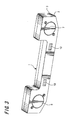
- FIGS. 1 to 3 are views showing an example of the structure of a loudspeaker box used for a bass reflex type loudspeaker apparatus to which the present invention is applied (FIG. 1 is an exploded view seen from the back surface side, FIG. 2 is an exploded view seen from the front surface side, and FIG. 3 is a perspective view seen from the front surface side).
- a loudspeaker box 1 is made of resin and includes a front surface side box 2 and a back surface side box 3. As shown in FIGS. 1 and 2, areas 2a and 3a where a loudspeaker unit 6 is installed are provided at one end of the front surface side box 2 and the back surface side box 3, respectively. Areas 2b and 3b where a loudspeaker unit 7 is installed are provided at the other end of the front surface side box 2 and the back surface side box 3, respectively.
- the loudspeaker units 6 and 7 each include a diaphragm to which a voice coil is attached and a magnetic circuit, and when an electrical signal is supplied to the voice coil, the magnetic circuit acts and makes the voice coil vibrate the diaphragm, so that a sound is generated.
- the front surface side box 2 and the back surface side box 3 are made to face each other with a rubber cushion 4 positioned in between and are fixed to each other by a plurality of screws 5, and so the loudspeaker box 1 is completed as shown in FIG. 3 (when the front surface side box 2 and the back surface side box 3 are fixed to each other with the loudspeaker units 6 and 7 installed, a bass reflex type loudspeaker apparatus is completed).
- the cushion 4 has such shape that a part thereof also serves as a partition board.
- the loudspeaker box 1 is mounted in an image display apparatus with the loudspeaker units 6 and 7 having been installed, and so stereo sound is listened to by means of the loudspeaker units 6 and 7 (alternatively, main audio is listened to by means of one loudspeaker unit, and sub audio is listened to by means of the other loudspeaker unit).
- FIG. 4 shows an example of the external structure of an image display apparatus in which the loudspeaker box 1 is installed.
- an image display apparatus 21 may be a television receiver, a computer display, or an apparatus in which a monitor, loudspeaker, codec and the like are integrally provided for a televised meeting.
- a space for installing a bass reflex type loudspeaker apparatus is provided in a position toward the front surface inside the image display apparatus 21, and the loudspeaker box 1 to which the loudspeaker units 6 and 7 are attached is installed in this space.
- a plurality of small holes for emitting sounds generated from the loudspeaker units 6 and 7 and from openings 10 and 12 (described later on) to the outside of the image display apparatus 21 are provided in positions corresponding to the positions where the loudspeaker units 6 and 7 are installed and to the positions of the openings 10 and 12 of the loudspeaker box 1 (however, as another structure, a gap may be provided in the bottom surface of the housing and so sounds will be emitted from the gap to the outside).
- the image display apparatus 21 is, for example, an apparatus for a televised meeting
- images and sounds from a meeting room of another party, decoded by a codec can be watched and listened to by means of the screen and the loudspeaker units 6 and 7 of the apparatus 21.
- the loudspeaker box 1 is made thin for the purpose of being installed in an image display apparatus in this manner.
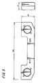
- FIG. 5 is a view showing the dimensions of the loudspeaker box 1.
- the loudspeaker box 1 is 260mm in total length (dimension in the lateral direction), 33mm in thickness (dimension in the anteroposterior direction) and 60mm in height (dimension in the vertical direction).
- an area 2c between the area 2a and the area 2b is continuous with the area 2a at one portion S1 but is separated from the area 2b by a wall 8 whose height is the same as the thickness of the front surface side box 2. Further, in the area 2c is formed a spiral route with a wall 9 whose height is the same as the thickness of the front surface side box 2.
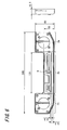
- FIG. 6 is a view showing the dimensions of the front surface side box 2.
- the front surface side box 2 is 260mm in total length, 16.5mm in thickness, and 60mm in height at the portion of areas 2a and 2b.
- the area 2c is 131mm in length and 32mm in height. In the area 2c, a spiral route of 5.5mm in width is formed by the wall 9 whose thickness is 2.5mm.
- FIG. 7 is a view in which the spiral route in the area 2c is shown by arrows of broken lines so as to show the route clearly.
- the spiral route extends in a direction perpendicular to a thickness direction of the front surface side box 2, with the portion S1 continuous with the area 2a serving as the start of the route, and is curved to have the total length longer than the length of the area 2c (to extend going back and forth more than once in the area 2c).
- the total length of the route to the end T1 is approximately 439mm.
- the front surface side box 2 has an opening 10 in a position corresponding to the end T1 of the spiral route.
- the front surface side box 2 has an opening 12 also in a position corresponding to the isolated portion 11.
- an area 3c positioned between the area 3a and the area 3b is continuous with the area 3b at one portion S2 but is separated from the area 3a by a wall 13 whose height is the same as the thickness of the back surface side box 3.
- a spiral route is formed by a wall 14 in the same manner as in the area 2c of the front surface side box 2.
- the dimensions of the back surface side box 3 and the dimensions of the area 3c are as a whole the same as the dimensions of the front surface side box 2 and the dimensions of the area 2c shown in FIG. 6.
- the width of the spiral route in the area 3c and the total length thereof from the start (the portion S2 continuous with the area 3b) to the end T2 are also the same as the width and total length of the spiral route in the area 2c.
- FIG. 8 is a view in which the spiral route in the area 3c is shown by arrows of broken lines so as to show the route clearly.
- the cushion 4 is shaped like a window frame at the portions corresponding to the areas 2a and 3a and the areas 2b and 3b, but is shaped like a sheet at the portion corresponding to the areas 2c and 3c, and therefore, the cushion 4 also functions as a partition board which separates the area 2c and the area 3c.
- the cushion 4 In the sheet-like portion of the cushion 4, however, only a hole 15 is provided in a position corresponding to the end T2 of the spiral route in the area 3c.
- the portion 11 isolated from the spiral route is provided, and the position thereof corresponds to the position of the hole 15 of the cushion 4.
- the area 2c of the front surface side box 2 and the area 3c of the back surface side box 3 are separated by the cushion 4, and so the space other than both end portions in the loudspeaker box (space of 131mm as shown in FIG. 6) is divided into a space on the front surface side and a space on the back surface side.
- a duct having a spiral route as shown by the arrows of broken lines in FIG. 7 is formed with the area 2c and cushion 4.
- the end T1 of the spiral route leads to the opening 10 of the front surface side box 2. Therefore, regarding this duct, the portion S1 continuous with the area 2a is an internal opening, and the opening 10 of the front surface side box 2 is an external opening. Then, with the loudspeaker unit 6 being installed in the areas 2a and 3a, a sound generated from the back surface of the loudspeaker unit 6 is emitted from the opening 10 of the front surface side box 2 to the outside through this duct.
- a duct having a spiral route as shown by the arrows of broken lines in FIG. 8 is formed with the area 3c and the cushion 4.
- the end T2 of the spiral route leads to the opening 12 of the front surface side box 2 via the hole 15 in the cushion 4 and the isolated portion 11 in the area 2c of the front surface side box 2. Therefore, regarding this duct, the portion S2 continuous with the area 3b is an internal opening, and the opening 12 of the front surface side box 2 is an external opening. Then, with the loudspeaker unit 7 being installed in the areas 2b and 3b, a sound generated from the back surface of the loudspeaker unit 7 is emitted from the opening 12 of the front surface side box 2 to the outside through this duct.
- one of the two bass reflex ducts of the loudspeaker units 6 and 7 is arranged toward the front of the loudspeaker apparatus and the other arranged toward the rear of the loudspeaker apparatus.
- the two ducts are arranged with a certain distance from each other in an anteroposterior direction (thickness direction) of the loudspeaker apparatus.
- each of routes of the two ducts is extended in a direction perpendicular (vertical and lateral directions of the loudspeaker apparatus) to an anteroposterior direction (thickness direction) of the loudspeaker apparatus, and is curved within a plane perpendicular to the anteroposterior direction (within planes in vertical and lateral directions of the loudspeaker apparatus).
- the routes of the two ducts can be extended in vertical and lateral directions of the loudspeaker apparatus without restricting each other and can be made to go back and forth within planes in the vertical and lateral directions of the loudspeaker apparatus. Accordingly, each of the routes of the two ducts can be made long, though the loudspeaker box 1 is made thin.
- a bass reflex type loudspeaker apparatus can be installed in a narrow space, and sounds generated from the back surfaces of the loudspeaker units 6 and 7 of this bass reflex type loudspeaker apparatus can be emitted to the outside from the bass reflex ducts whose routes are made long.
- the space inside the loudspeaker box 1 is divided into a space on the front surface side and a space on the back surface side, using the cushion 4 parallel to an anteroposterior direction of the loudspeaker apparatus as a partition board, and one duct is arranged in each space.
- the two ducts are arranged with a certain distance from each other in an anteroposterior direction (thickness direction) of the loudspeaker apparatus with a simplified structure and without high cost.
- the cushion 4 has the hole 15, which connects the space on the front surface side and the space on the back surface side, in a position corresponding to the end T2 of the spiral route of the duct in the space on the back surface side.
- the portion 11 connected to the space on the back surface side by means of this hole 15 is isolated from the route of the duct.
- the front surface side box 2 has the opening 10 (external opening for the duct on the front surface side) in a position corresponding to the position of the end T1 of the spiral route of the duct in the space on the front surface side, and has the opening 12 (external opening for the duct on the back surface side) in a position corresponding to the position of the hole 15.
- the loudspeaker box 1 is made thinner, sounds generated from the back surfaces of the loudspeaker units 6 and 7 can be emitted in the same direction (toward the front of the loudspeaker apparatus) through the two ducts whose routes are elongated.
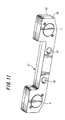
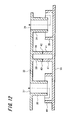
- FIGS. 9 to 11 are views showing the structure of a loudspeaker box in which pipe-shaped ducts are provided to be compared
- FIG. 9 is an exploded view seen from the back surface side
- FIG. 10 is an exploded view seen from the front surface side
- FIG. 11 is a perspective view seen from the front surface side.
- a loudspeaker box 31 has the shape and size similar to those of the loudspeaker box 1 as a whole, but is different from the loudspeaker box 1 only with respect to the duct structure. For that reason, only the structure of the duct is to be explained.
- a pipe 34 which extends in an anteroposterior direction (thickness direction) of the loudspeaker apparatus is formed in a position toward an area where a loudspeaker unit 6 is installed.
- a pipe 35 which similarly extends in a thickness direction is formed in a position toward an area where a loudspeaker unit 7 is installed.
- the length of these pipes 34 and 35 is larger than the thickness of the front surface side box 32 but is smaller than the thickness of the space inside the loudspeaker box 31.
- the front surface side box 32 has external openings 36 and 37 of these pipes 34 and 35.
- a wall 38 whose height is the same as the thickness of the front surface side box 32 is formed in a position between the pipes 34 and 35.
- a pipe 39 whose internal diameter is larger than the external diameter of the pipe 34 and whose length is smaller than that of the pipe 34 is formed in a position corresponding to the position of the pipe 34 of the front surface side box 32.
- a pipe 40 whose internal diameter is larger than the external diameter of the pipe 35 and whose length is smaller than that of the pipe 35 is formed in a position corresponding to the position of the pipe 35 of the front surface side box 32.
- a wall 41 whose height is the same as the thickness of the back surface side box 33 is formed in a position corresponding to the position of the wall 38 of the front surface side box 32.
- the internal opening of the pipe 34 of the front surface side box 32 is positioned inside the pipe 39 of the back surface side box 33 without touching the pipe 39.
- the internal opening of the pipe 35 of the front surface side box 32 is positioned inside the pipe 40 of the back surface side box 33 without touching the pipe 40.
- FIG. 13 is a diagram showing the measurement results of the frequency characteristic of a bass reflex type loudspeaker apparatus in which the loudspeaker units 6 and 7 were attached to the loudspeaker box 1 according to an embodiment of the present invention, with the measurement results of the frequency characteristic of a bass reflex type loudspeaker apparatus in which the same loudspeaker units 6 and 7 were attached to the loudspeaker box 31 in FIGS. 9 to 11.
- the level in a low range of around 200Hz was low, whereas in the case of the loudspeaker box 1, the level in the low sound range around 200Hz was greatly improved. In this way, such measurement results were obtained in which the characteristic of a low sound range was greatly improved regarding the loudspeaker box 1 to which the present invention was applied.
- external openings (openings 10 and 12) of two ducts are formed in the front surface side box 2 in the loudspeaker box 1 in the above described example, external openings of two ducts may be formed in the back surface side box 3 as another example.
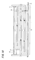
- FIG. 14 is a view showing an example in which an S-shaped route is formed in the area 2c.
- the S-shaped route is shown by an arrow of a broken line so as to show the S-shaped route clearly in a similar manner to FIG. 7.
- the end T1, the opening 10, the portion 11 and the opening 12, which are shown in FIG. 7, are given the same numerals, and the positions thereof are modified to be shown suitably for the S-shaped route.
- the cushion 4 is used as a partition board and the space inside the loudspeaker box 1 is divided into a space on the front surface side and a space on the back surface side, and one duct is arranged in each space.
- two ducts may be arranged with a certain distance from each other in an anteroposterior direction (thickness direction) of the loudspeaker apparatus.
- two spirally-curved hollow tubes are arranged with a certain distance from each other in an anteroposterior direction of the loudspeaker apparatus, and each tube is used as a duct.
- the route of each duct is curved within planes in vertical and lateral directions of the loudspeaker apparatus.
- the route of each duct may be extended in vertical and lateral directions of the loudspeaker apparatus, but may not be curved within planes in vertical and lateral directions of the loudspeaker apparatus and may be curved in an anteroposterior direction (thickness direction) of the loudspeaker apparatus.
- the routes of ducts can be made long in comparison with those of pipe-shaped ducts in related art, in the case where a loudspeaker box is thinned.
- the present invention is applied to a loudspeaker box capable of two loudspeaker units being installed, the present invention may also be applied to a loudspeaker box in which only one loudspeaker unit can be installed.
- the present invention can also be applied to a system stereo, a radio, a cassette recorder, in-car audio equipment, an independent loudspeaker apparatus and the like. It should be understood by those skilled in the art that various modifications, combinations, sub-combinations and alterations may occur depending on design requirements and other factors insofar as they are within the scope of the appended claims or the equivalents thereof.
- a bass reflex type loudspeaker apparatus in which a long route of a bass reflex duct is obtained in the case where a loudspeaker box is made thin.
- the bass reflex duct is provided in the loudspeaker box such that the route thereof is extended in a direction perpendicular to an anteroposterior direction of the loudspeaker apparatus and is curved.
Landscapes
- Engineering & Computer Science (AREA)
- General Engineering & Computer Science (AREA)
- Health & Medical Sciences (AREA)
- Otolaryngology (AREA)
- Physics & Mathematics (AREA)
- Acoustics & Sound (AREA)
- Signal Processing (AREA)
- Mechanical Engineering (AREA)
- Details Of Audible-Bandwidth Transducers (AREA)
- Obtaining Desirable Characteristics In Audible-Bandwidth Transducers (AREA)
Applications Claiming Priority (1)
| Application Number | Priority Date | Filing Date | Title |
|---|---|---|---|
| JP2005065995A JP4306627B2 (ja) | 2005-03-09 | 2005-03-09 | バスレフ型スピーカー装置,スピーカーボックス及び画像表示装置 |
Publications (1)
| Publication Number | Publication Date |
|---|---|
| EP1703766A2 true EP1703766A2 (fr) | 2006-09-20 |
Family
ID=36658861
Family Applications (1)
| Application Number | Title | Priority Date | Filing Date |
|---|---|---|---|
| EP06251220A Withdrawn EP1703766A2 (fr) | 2005-03-09 | 2006-03-08 | Haut-parleur de type à réflexion des basses et appareil d'affichage d'image |
Country Status (6)
| Country | Link |
|---|---|
| US (1) | US7410029B2 (fr) |
| EP (1) | EP1703766A2 (fr) |
| JP (1) | JP4306627B2 (fr) |
| KR (1) | KR101217411B1 (fr) |
| CN (1) | CN1832632B (fr) |
| TW (1) | TW200709711A (fr) |
Cited By (2)
| Publication number | Priority date | Publication date | Assignee | Title |
|---|---|---|---|---|
| CN104837082A (zh) * | 2014-02-07 | 2015-08-12 | Lg电子株式会社 | 电子设备 |
| RU2645014C2 (ru) * | 2012-12-28 | 2018-02-15 | Сони Корпорейшн | Устройство отображения |
Families Citing this family (21)
| Publication number | Priority date | Publication date | Assignee | Title |
|---|---|---|---|---|
| JP2006345294A (ja) * | 2005-06-09 | 2006-12-21 | Toshiba Corp | 映像表示装置 |
| KR100663648B1 (ko) * | 2005-08-05 | 2007-01-03 | 삼성전자주식회사 | 모니터장치 |
| FI122126B (fi) * | 2005-10-05 | 2011-08-31 | Genelec Oy | Refleksikaiutinrakenne |
| CN100499971C (zh) * | 2005-11-04 | 2009-06-10 | 群康科技(深圳)有限公司 | 平面显示器 |
| JP2008124855A (ja) * | 2006-11-14 | 2008-05-29 | Funai Electric Co Ltd | スピーカ装置 |
| CN101212828A (zh) * | 2006-12-27 | 2008-07-02 | 鸿富锦精密工业(深圳)有限公司 | 电子设备及其采用的声音模组 |
| TWI419574B (zh) * | 2006-12-29 | 2013-12-11 | Hon Hai Prec Ind Co Ltd | 電子設備及其採用的聲音模組 |
| JP4366614B2 (ja) | 2007-08-24 | 2009-11-18 | ソニー株式会社 | スピーカシステムおよび嵌め込み装置 |
| KR20100019642A (ko) * | 2008-08-11 | 2010-02-19 | 삼성전자주식회사 | 스피커장치 및 이를 구비하는 영상표시장치 |
| US8002078B2 (en) * | 2009-02-19 | 2011-08-23 | Bose Corporation | Acoustic waveguide vibration damping |
| JP5189022B2 (ja) * | 2009-04-01 | 2013-04-24 | ミネベア株式会社 | スピーカシステム |
| CN102006529B (zh) * | 2009-08-28 | 2013-04-24 | 鸿富锦精密工业(深圳)有限公司 | 倒相式音箱 |
| CN102045613A (zh) * | 2009-10-22 | 2011-05-04 | 鸿富锦精密工业(深圳)有限公司 | 扬声器模组 |
| US8869931B1 (en) * | 2013-06-13 | 2014-10-28 | Harman International Industries, Inc. | Bass-reflex loudspeaker assembly for mobile devices |
| US9392358B2 (en) * | 2014-10-28 | 2016-07-12 | Robert Bosch Gmbh | Waveguide for shaping sound waves |
| US9799321B2 (en) * | 2015-12-09 | 2017-10-24 | Jl Audio, Inc. | Waveguide for a boat |
| USD832235S1 (en) * | 2016-07-25 | 2018-10-30 | Bose Corporation | Sub-woofer |
| JP7069699B2 (ja) * | 2017-12-25 | 2022-05-18 | ヤマハ株式会社 | スピーカ構造 |
| CN209545842U (zh) * | 2019-01-23 | 2019-10-25 | 深圳市赛源电子有限公司 | 一种低音反射式音箱 |
| KR102801260B1 (ko) | 2020-02-10 | 2025-04-29 | 삼성전자주식회사 | 스피커 및 스피커를 위한 음향 출력 경로를 포함하는 휴대용 단말기 |
| CN115951548A (zh) * | 2022-12-30 | 2023-04-11 | 峰米(重庆)创新科技有限公司 | 投影仪 |
Citations (2)
| Publication number | Priority date | Publication date | Assignee | Title |
|---|---|---|---|---|
| JP2003061177A (ja) | 2001-08-15 | 2003-02-28 | Sony Corp | バスレフ型スピーカキャビネットのダクト |
| JP2003324795A (ja) | 2002-05-08 | 2003-11-14 | Sony Corp | スピーカおよびその駆動方法 |
Family Cites Families (25)
| Publication number | Priority date | Publication date | Assignee | Title |
|---|---|---|---|---|
| US3044570A (en) * | 1957-04-08 | 1962-07-17 | Watts Ltd Cecil E | Loudspeakers |
| US3327808A (en) * | 1965-06-10 | 1967-06-27 | Dyna Empire Inc | Loud speaker housing |
| US3923124A (en) * | 1974-01-02 | 1975-12-02 | John P Hancock | Back loaded folded corner horn speaker |
| US3993162A (en) * | 1975-06-20 | 1976-11-23 | Kenneth Juuti | Acoustic speaker system |
| US4168761A (en) * | 1976-09-03 | 1979-09-25 | George Pappanikolaou | Symmetrical air friction enclosure for speakers |
| US4509184A (en) * | 1982-03-18 | 1985-04-02 | Pioneer Electronic Corporation | Stereo sound system |
| JPS6282899A (ja) * | 1985-10-08 | 1987-04-16 | Sony Corp | スピ−カシステム |
| EP0252522B1 (fr) * | 1986-07-11 | 1993-03-10 | Matsushita Electric Industrial Co., Ltd. | Appareil de reproduction sonore pour utilisation dans un véhicule |
| US4942939A (en) * | 1989-05-18 | 1990-07-24 | Harrison Stanley N | Speaker system with folded audio transmission passage |
| US5197103A (en) * | 1990-10-05 | 1993-03-23 | Kabushiki Kaisha Kenwood | Low sound loudspeaker system |
| JP3202220B2 (ja) * | 1990-10-09 | 2001-08-27 | パイオニア株式会社 | 車載用リアトレイスピーカシステム |
| JPH0575797U (ja) * | 1992-03-24 | 1993-10-15 | 株式会社河合楽器製作所 | 電子鍵盤楽器のスピーカ装置 |
| JP3479993B2 (ja) * | 1993-03-31 | 2003-12-15 | 松下電器産業株式会社 | スピーカ装置 |
| US6278789B1 (en) * | 1993-05-06 | 2001-08-21 | Bose Corporation | Frequency selective acoustic waveguide damping |
| US5343535A (en) * | 1993-05-07 | 1994-08-30 | Marshall Ronald N | Loudspeaker device |
| DE659030T1 (de) * | 1993-12-16 | 1996-01-04 | Toshiba Kawasaki Kk | Lautsprechersystem für Fernsehgeräte. |
| US5821471A (en) * | 1995-11-30 | 1998-10-13 | Mcculler; Mark A. | Acoustic system |
| JPH11136786A (ja) * | 1997-10-31 | 1999-05-21 | Sony Corp | スピーカ装置 |
| US6411721B1 (en) * | 1997-12-19 | 2002-06-25 | William E. Spindler | Audio speaker with harmonic enclosure |
| JPH11205884A (ja) * | 1998-01-07 | 1999-07-30 | Sony Corp | スピーカ装置 |
| JPH11205886A (ja) * | 1998-01-14 | 1999-07-30 | Sony Corp | スピーカ装置 |
| JPH11234780A (ja) * | 1998-02-16 | 1999-08-27 | Sony Corp | スピーカ装置 |
| TW553419U (en) * | 2002-09-26 | 2003-09-11 | Wistron Corp | Woofer module of a portable computer |
| JP3995632B2 (ja) * | 2003-05-16 | 2007-10-24 | シャープ株式会社 | バスレフ型スピーカ装置及び該バスレフ型スピーカ装置を内蔵した映像表示装置 |
| US7218747B2 (en) * | 2003-12-05 | 2007-05-15 | Nick Huffman | Externally ported loudspeaker enclosure |
-
2005
- 2005-03-09 JP JP2005065995A patent/JP4306627B2/ja not_active Expired - Fee Related
-
2006
- 2006-03-01 US US11/364,192 patent/US7410029B2/en not_active Expired - Fee Related
- 2006-03-07 TW TW095107685A patent/TW200709711A/zh not_active IP Right Cessation
- 2006-03-08 KR KR1020060021546A patent/KR101217411B1/ko not_active Expired - Fee Related
- 2006-03-08 EP EP06251220A patent/EP1703766A2/fr not_active Withdrawn
- 2006-03-09 CN CN200610058944XA patent/CN1832632B/zh not_active Expired - Fee Related
Patent Citations (2)
| Publication number | Priority date | Publication date | Assignee | Title |
|---|---|---|---|---|
| JP2003061177A (ja) | 2001-08-15 | 2003-02-28 | Sony Corp | バスレフ型スピーカキャビネットのダクト |
| JP2003324795A (ja) | 2002-05-08 | 2003-11-14 | Sony Corp | スピーカおよびその駆動方法 |
Cited By (15)
| Publication number | Priority date | Publication date | Assignee | Title |
|---|---|---|---|---|
| RU2645014C2 (ru) * | 2012-12-28 | 2018-02-15 | Сони Корпорейшн | Устройство отображения |
| US10136203B2 (en) | 2012-12-28 | 2018-11-20 | Saturn Licensing Llc | Display device |
| EP2905973B1 (fr) * | 2014-02-07 | 2018-04-04 | LG Electronics Inc. | Ensemble de haut-parleurs intégré dans un appareil electronique |
| CN104837082A (zh) * | 2014-02-07 | 2015-08-12 | Lg电子株式会社 | 电子设备 |
| EP3331252A1 (fr) * | 2014-02-07 | 2018-06-06 | LG Electronics Inc. | Ensemble de haut-parleurs intégré dans un appareil electronique |
| US10028044B2 (en) | 2014-02-07 | 2018-07-17 | Lg Electronics Inc. | Electronic device including a speaker assembly |
| KR20150093515A (ko) * | 2014-02-07 | 2015-08-18 | 엘지전자 주식회사 | 전자 디바이스 |
| US10299022B2 (en) | 2014-02-07 | 2019-05-21 | Lg Electronics Inc. | Electronic device including a speaker assembly |
| EP3585065A1 (fr) * | 2014-02-07 | 2019-12-25 | Lg Electronics Inc. | Dispositif électronique |
| KR102169278B1 (ko) | 2014-02-07 | 2020-10-23 | 엘지전자 주식회사 | 전자 디바이스 |
| US10959000B2 (en) | 2014-02-07 | 2021-03-23 | Lg Electronics Inc. | Electronic device including a speaker assembly |
| EP3849208A1 (fr) * | 2014-02-07 | 2021-07-14 | LG Electronics Inc. | Dispositif électronique |
| US11310577B2 (en) | 2014-02-07 | 2022-04-19 | Lg Electronics Inc. | Electronic device |
| US11665458B2 (en) | 2014-02-07 | 2023-05-30 | Lg Electronics Inc. | Electronic device |
| US12069417B2 (en) | 2014-02-07 | 2024-08-20 | Lg Electronics Inc. | Electronic device |
Also Published As
| Publication number | Publication date |
|---|---|
| US7410029B2 (en) | 2008-08-12 |
| KR20060097621A (ko) | 2006-09-14 |
| CN1832632A (zh) | 2006-09-13 |
| TW200709711A (en) | 2007-03-01 |
| TWI309534B (fr) | 2009-05-01 |
| KR101217411B1 (ko) | 2013-01-03 |
| JP4306627B2 (ja) | 2009-08-05 |
| JP2006253948A (ja) | 2006-09-21 |
| US20060201739A1 (en) | 2006-09-14 |
| CN1832632B (zh) | 2011-03-23 |
Similar Documents
| Publication | Publication Date | Title |
|---|---|---|
| US7410029B2 (en) | Bass reflex type loudspeaker apparatus, loudspeaker box and image display apparatus | |
| US7743877B2 (en) | Speaker system | |
| US5197103A (en) | Low sound loudspeaker system | |
| TW200838345A (en) | Speaker apparatus and display apparatus with speaker | |
| US8150077B2 (en) | Microphone | |
| KR100202342B1 (ko) | 오디오 또는 비디오 장치 | |
| KR102227138B1 (ko) | 관로 일체형 리시버 모듈 | |
| US1837755A (en) | Translating device | |
| EP2214418A2 (fr) | Unité de microphone | |
| US7302076B2 (en) | Low profile speaker and system | |
| MX2007005500A (es) | Dispositivo de comunicacion movil. | |
| CN113796095A (zh) | 扬声器设备、扬声器和结构 | |
| JP2009267577A (ja) | 薄型表示装置 | |
| CN115209252A (zh) | 扬声器 | |
| WO2006104101A1 (fr) | Systeme de haut-parleurs et dispositif d’affichage | |
| WO2002003751A1 (fr) | Systeme de haut-parleur et dispositif de suppression de bruit | |
| JPH11122560A (ja) | スピーカー振動防止装置を有するテレビ | |
| CN103339562B (zh) | 投射型显示装置 | |
| CN118762620A (zh) | 显示设备 | |
| CN118609487A (zh) | 显示设备 | |
| JP4643626B2 (ja) | スピーカ装置 | |
| CN1939088A (zh) | 分布式声箱 | |
| JP2008131541A (ja) | スピーカ装置 | |
| JP3473279B2 (ja) | スピーカ装置 | |
| JPH02202298A (ja) | 多重共鳴型スピーカシステム |
Legal Events
| Date | Code | Title | Description |
|---|---|---|---|
| PUAI | Public reference made under article 153(3) epc to a published international application that has entered the european phase |
Free format text: ORIGINAL CODE: 0009012 |
|
| AK | Designated contracting states |
Kind code of ref document: A2 Designated state(s): AT BE BG CH CY CZ DE DK EE ES FI FR GB GR HU IE IS IT LI LT LU LV MC NL PL PT RO SE SI SK TR |
|
| AX | Request for extension of the european patent |
Extension state: AL BA HR MK YU |
|
| STAA | Information on the status of an ep patent application or granted ep patent |
Free format text: STATUS: THE APPLICATION HAS BEEN WITHDRAWN |
|
| 18W | Application withdrawn |
Effective date: 20130430 |