EP1703829B1 - Für standby- oder reaktionszustand ausgeführtes elektrisches haushaltslebensmittelzubereitungsgerät - Google Patents
Für standby- oder reaktionszustand ausgeführtes elektrisches haushaltslebensmittelzubereitungsgerät Download PDFInfo
- Publication number
- EP1703829B1 EP1703829B1 EP04816485A EP04816485A EP1703829B1 EP 1703829 B1 EP1703829 B1 EP 1703829B1 EP 04816485 A EP04816485 A EP 04816485A EP 04816485 A EP04816485 A EP 04816485A EP 1703829 B1 EP1703829 B1 EP 1703829B1
- Authority
- EP
- European Patent Office
- Prior art keywords
- speed
- motor
- load
- threshold
- appliance
- Prior art date
- Legal status (The legal status is an assumption and is not a legal conclusion. Google has not performed a legal analysis and makes no representation as to the accuracy of the status listed.)
- Expired - Lifetime
Links
- 238000002360 preparation method Methods 0.000 title description 4
- 235000021478 household food Nutrition 0.000 title description 2
- 230000007423 decrease Effects 0.000 claims description 20
- 235000013305 food Nutrition 0.000 claims description 15
- 230000009467 reduction Effects 0.000 claims description 9
- 230000005534 acoustic noise Effects 0.000 claims description 8
- 230000003247 decreasing effect Effects 0.000 claims description 6
- 238000012544 monitoring process Methods 0.000 claims description 3
- 230000005355 Hall effect Effects 0.000 abstract description 2
- 235000013351 cheese Nutrition 0.000 description 10
- 238000010586 diagram Methods 0.000 description 4
- 238000005259 measurement Methods 0.000 description 4
- 230000033228 biological regulation Effects 0.000 description 3
- 238000002156 mixing Methods 0.000 description 3
- 230000009471 action Effects 0.000 description 2
- 230000008859 change Effects 0.000 description 2
- 230000003068 static effect Effects 0.000 description 2
- 230000006978 adaptation Effects 0.000 description 1
- 230000001276 controlling effect Effects 0.000 description 1
- 230000001419 dependent effect Effects 0.000 description 1
- 230000000694 effects Effects 0.000 description 1
- 238000000227 grinding Methods 0.000 description 1
- 238000004898 kneading Methods 0.000 description 1
- 235000013372 meat Nutrition 0.000 description 1
- 230000009347 mechanical transmission Effects 0.000 description 1
- 238000000034 method Methods 0.000 description 1
- 230000004048 modification Effects 0.000 description 1
- 238000012986 modification Methods 0.000 description 1
- 230000003287 optical effect Effects 0.000 description 1
- 238000012545 processing Methods 0.000 description 1
- 230000001105 regulatory effect Effects 0.000 description 1
- 230000006641 stabilisation Effects 0.000 description 1
- 238000011105 stabilization Methods 0.000 description 1
- 235000013311 vegetables Nutrition 0.000 description 1
Images

Classifications
-
- A—HUMAN NECESSITIES
- A47—FURNITURE; DOMESTIC ARTICLES OR APPLIANCES; COFFEE MILLS; SPICE MILLS; SUCTION CLEANERS IN GENERAL
- A47J—KITCHEN EQUIPMENT; COFFEE MILLS; SPICE MILLS; APPARATUS FOR MAKING BEVERAGES
- A47J43/00—Implements for preparing or holding food, not provided for in other groups of this subclass
- A47J43/04—Machines for domestic use not covered elsewhere, e.g. for grinding, mixing, stirring, kneading, emulsifying, whipping or beating foodstuffs, e.g. power-driven
- A47J43/07—Parts or details, e.g. mixing tools, whipping tools
- A47J43/08—Driving mechanisms
Definitions
- the invention relates to the field of household appliances, and more particularly to the field of household appliances for the preparation of food.
- these devices include single or multifunctional food processors of all kinds, and for example blenders, drummers, meat grinders, juicers, centrifuges and other electric knives.
- the invention relates more particularly to an arrangement of the control and control device of the electric motor equipping such devices. It aims more specifically the management of the speed of this engine according to its load.
- culinary robots are equipped with one or more electric motors that can be of various types, and for example universal motors, DC or "brushless". These motors are frequently powered so that they rotate at variable speed, to drive a rotary tool dependent on the type of device.
- the motor In operation, the motor is powered to provide sufficient torque to perform the necessary operations.
- the resistant torque applied to the motor decreases, for example because the food to grind or chop were indeed, the engine speed increases according to the characteristic curve of the engine. This increase in no-load speed is particularly marked for certain types of engines such as universal motors.
- the described apparatus comprises a control device which automatically ensures a stabilization of the engine speed when the load, or the resistant torque applied to the engine fluctuates slightly. Compensation systems make it possible to maintain the engine speed at the fixed setpoint, despite the variations in torque. However, this system maintains a high level of speed even when the load has disappeared, thus generating the cons of consumption and noise already mentioned.
- This document discloses a traditional regulation in which the speed of operation of the apparatus tends to remain constant when the load decreases or increases. The operating speed of the device does not decrease or increase permanently.
- the document EP 0 480 309 describes another solution that has been proposed to limit the acoustic noise generated in appliances of the type of kitchen robots.
- Such a device comprises means for limiting the motor speed to a maximum speed of use. However, this speed is not adapted according to the load applied to the engine, and the acoustic noise remains high at reduced load.
- the document JP 11-225891 describes a mixer that automatically stops mixing as soon as the food has reached a sufficient grinding level.
- This device therefore comprises means for detecting the state of the material in the mixing bowl, and stops the engine of the apparatus when the degree of kneading is considered sufficient.
- This degree of mixing can be estimated in various ways, and in particular by analyzing a light signal passing through the material contained in the bowl, or even by the measurement of the current supplying the motor.
- a disadvantage of this type of device is that it is suitable only for one-off operations, since the motor is stopped after each operation. It is therefore necessary for the user to restart the engine by an action on the device.
- this type of device is not suitable for tasks in which the food is brought into the appliance in several times, and discontinuously, for example when it comes to grating vegetables or cheese .
- a problem that the invention seeks to solve is that of excessive power consumption, and the inadvertent generation of acoustic noises when the apparatus operates almost "empty", that is to say under very low load or zero load.
- Another object of the invention is to allow to sequence the realization of discontinuous operations, without requiring intervention from the user.
- the invention thus relates to an appliance for food preparation.
- this apparatus comprises an electric motor adapted to drive a variable speed rotary tool and a control / control device comprising means for operating the motor according to at least a first operating mode and a second operating mode.
- This apparatus also includes means for evaluating the load or the load torque applied to the motor, as well as means for automatically switching the operation of the apparatus from the first operating mode to the second operating mode when said load falls below the operating mode. a first predetermined threshold, and wherein, when the load goes from a value greater than the first threshold to a value lower than the first threshold, the operating speed of the device decreases perennially.
- this apparatus is characterized in that when the load goes from a value greater than the first threshold to a value lower than the first threshold, the operating speed of the apparatus decreases perennially to a value non-zero, and in that the control / control device also comprises means for automatically switching the operation of the apparatus of the second mode of operation to the first mode of operation when said load returns above a second predetermined threshold , and in that, when the load goes from a value lower than the second threshold to a value greater than the second threshold, the operating speed of the apparatus increases in a perennial manner.
- the invention consists in providing a monitoring of the load applied to the motor. This not only reduces the speed of the latter automatically when it is no longer necessary to exert a significant torque, but also to increase the speed when it is detected again the presence of food to be treated.
- the system is able to automatically go into "sleep mode" (second mode of operation), reducing the speed automatically in the case of idling of the tool, while remaining ready to provide a higher speed (first mode of operation) When this becomes necessary again.
- This management is done completely automatically without the user having any action to perform.
- the speed of the motor is optimized. Similarly, it avoids an untimely generation of acoustic noise in the phases where the engine runs empty.
- the operating speed of the apparatus decreases by at least 5%; and when the load goes from a value lower than the second threshold to a value greater than the second threshold, the operating speed of the apparatus increases by at least 5%.
- the first mode of operation may be defined by a first reference speed and the second mode of operation may be defined by a second reference speed.
- the speed applied to the motor can be defined by a speed reference, when the apparatus comprises a speed sensor associated with a control device.
- the means for increasing or decreasing the speed may consist of a modification of the motor speed reference.
- the speed applied to the motor may also depend on the characteristic of the torque / speed curve of the motor, when the motor is not regulated in speed. In the latter case, the speed depends on the engine load.
- the motor supply voltage makes it possible to define the characteristic of the torque / speed curve of the motor.
- Means for increasing or decreasing the speed may be means for changing the motor supply voltage.
- the resistive torque threshold causing the speed reduction can be identical, with a hysteresis close to the threshold at which the nominal speed of the motor is automatically restored.
- these two thresholds may also be different.
- these predetermined load thresholds for the reduction and / or the automatic increase of the motor speed, can also be variable, and depend on the value of the initial speed.
- the resistive torque threshold generating the standby may not be the same depending on whether the nominal speed is important or not.
- This characteristic makes it possible to adapt to different types of operation, for example dedicated to the treatment of different types of food with the same appliance.
- the value of the speed after reduction is a function of the value of the measured load.
- the apparatus may be arranged to further decrease the speed when the load remains below the predetermined threshold for this standby for a predetermined time.
- the speed can be further reduced, or even canceled, when the standby state continues, meaning that the operations on the food are finished.
- the means for detecting the load applied to the motor can be very varied.
- the torque can thus be measured by a force sensor provided for this purpose, or else by measurements of electrical parameters specific to the motor, such as the current consumed by the motor or the voltage at its terminals. It is also possible to detect a change in load by measuring the difference between a set speed and a measured speed, or even by measuring acoustic noise.
- Load fluctuations are also a way of knowing that the tool is working. It is possible to take into account load fluctuations in the estimation of the torque. Thus the estimated torque can be increased if the load fluctuates. Equivalently, a load fluctuation can be taken into account by increasing the torque threshold.
- the motor speed is reduced to a non-zero value when the load falls below the first predetermined threshold.
- This arrangement makes it easier to detect an increase in load on the tool above the second predetermined threshold.
- This arrangement also makes it possible to signal to the user that the device is in a standby state.
- a indicating device could be envisaged, including a luminous indicator device.
- the speed of the motor is reduced by at least 15% when the load falls below the first predetermined threshold.
- the reference speed is the operating speed of the motor for said load in the absence of the device according to the invention, and not the speed of the motor in the presence of a load greater than the first predetermined threshold.
- the speed of the motor is reduced by at least 30% when the load falls below the first predetermined threshold. This arrangement makes it possible to obtain an even greater decrease in the noise of the apparatus.
- the present invention is particularly advantageous in the case of a universal motor, because it avoids an excessive increase in speed when the applied load has decreased significantly and the motor is not controlled in speed.
- a food processor (1) finds application in multiple household appliances for the treatment of foods, among which as illustrated in FIG. figure 1 , a food processor (1).
- a robot (1) conventionally comprises a frame (2) incorporating an electric motor (3) powered from the grid voltage (4), or an autonomous power source. It is controlled by means of an electronic or electromechanical control device (5).
- the robot (1) is equipped with a speed selector (6) allowing the user to vary the speed applied to the motor (3).
- the invention also covers devices in which the user can not select the speed.
- the electric motor (3) rotates a tool (10) which in the illustrated form is a disc carrying a cheese grater disposed in the upper part of a bowl (11).
- the mechanical transmission between the electric motor (3) and the tool (10) can be done in various ways, without affecting the principle of the invention.
- control / control device (5) makes it possible to ensure a variation of the speed applied to the electric motor (3), as a function of an estimate or a measurement of the resistant torque applied to this engine.
- the resistive torque can be estimated by measuring the current flowing in the electric motor (3), via a sensor (15) of the Shunt type, Hall effect or other.
- this resistive torque can also be evaluated differently, by voltage measurements at the terminals of the electric fitter (3) or directly via a force sensor.
- the electric motor (3) is powered by means of a power circuit (16) which can for example be a triac or thyristor or diode based phase switching control, or a chopper type control integrating static switches based on IGBTs or other transistors or power thyristors, conventionally associated with freewheeling diodes.
- a power circuit (16) which can for example be a triac or thyristor or diode based phase switching control, or a chopper type control integrating static switches based on IGBTs or other transistors or power thyristors, conventionally associated with freewheeling diodes.
- the speed of the motor is controlled by the issuance of control commands (17) to these static switches, the commands being developed at an electronic card (7) of the control / command device (5), illustrated in FIG. figure 2 .
- the regulation of this speed as a function of the speed reference applied can be done in different ways, and in particular by PID controllers.
- the speed sensor (18) of the motor can be constituted by an optical fork which reacts to the passage of the teeth of a toothed wheel mounted on the axis of the electric motor (3), but of course any other type of speed sensor can be used without departing from the scope of the invention.
- the robot may not have a speed sensor, so the speed is not measured directly, but only estimated.
- the robot may also be devoid of speed control, the applied speed depending on the characteristic of the torque / speed curve of the motor and the applied load.
- the speed can adopt different values according to the estimated load.
- the information of the current (19) flowing in the electric motor (3), representative of the resistive torque applied to the motor is processed by a stage (20) analyzing said load, in order to deliver a signal (21) controlling the tilting of the setpoint applied between two values.
- the nominal speed setpoint is developed by the speed selector (6) accessible by the user.
- the other speed instruction (23) can be either preprogrammed at the electronic card, or fixed with possibly a possibility of adjustment or dynamic adaptation according to the nominal speed setpoint.
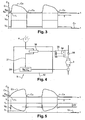
- the switching between the two speed commands corresponding to two operating modes is done by comparing the estimated load with two high and low thresholds (S B , S H ), according to the direction of variation of the load. (19).
- the control / command device (5) detects that the resistive torque (C 1 ) applied to the motor is weak, and below the high threshold (S H ). In this way, the speed reference applied to the motor is the low value (V o ).
- the apparatus is in a "sleep" mode, that is, in the second mode of operation.
- the resistive torque (C 2 ) applied to the motor increases, and the control / command device (5) causes the tilting of the rated speed command (V N ), that is to say according to the first operating mode.
- the torque (C 2 ) supplied by the motor rises to perform the mechanical force of cutting the piece of cheese.
- the resistant torque (C 3 ) applied to the motor decreases, to pass below a low value (S B ).
- the control / control device (5) causes the speed setpoint to go to the low value (V o ), corresponding to a standby mode, that is, say according to the second mode of operation.
- the speed can then increase when a new piece of cheese is introduced into the machine.
- the speed controller (26) may cause further reduction or even stopping of the engine.
- the invention also covers more economical motor supply circuits, in which a diode (33) is arranged in series with the electric motor (3) such as for example a universal motor, as illustrated in FIG. figure 4 .
- this diode (33) can be short-circuited by an appropriately controlled relay contact (34).
- the diode (33) When the diode (33) is short-circuited (or shunted), the full voltage is applied to the motor (3), which then rotates at its maximum speed for a given load.
- the control of the relay (35) is performed by a stage (36) of the electronic card (32) which combines the information coming from the selector of speed (6) (if it exists), and the signal (21) for comparing the resisting torque with respect to the predetermined threshold; developed by the stage (20) of the control / control device (5).
- the control / command device detects that the resistive torque (C 1 ) applied to the motor is low, and lower than the high threshold (S H ). In this way, the motor is powered with a reduced voltage.
- the device is in a "sleep" mode, according to the second mode of operation.
- the resistant torque applied to the motor increases.
- the engine speed starts to decrease, because the engine is not controlled in speed.
- the control / control device (5) causes the switching of the motor supply.
- the diode (33) is shunted and the motor (3) is powered at full voltage.
- the speed of the motor increases and then decreases under the effect of the increase in the load due to the mechanical force of cutting the piece of cheese.
- the resistive torque (C 3 ) applied to the motor decreases, to go below a low value (S B ).
- the control / control device (5) causes the switching of the power supply of the motor to the first mode of operation.
- the diode (33) is in series with the motor (3).
- the motor is powered with a reduced voltage.
- the device has returned to the "sleep" mode.
- the motor can be powered again at full voltage when a new piece of cheese is introduced into the unit.
- the speed V m reached in the absence of load with the device according to the invention may be greater than the minimum speed V i reached under load.
- the speed V m attained in the absence of a load with the device according to the invention is lower than the speed V n reached in the absence of a load without the device according to the invention.
- the difference in speed ⁇ V between the speed V m and the speed V n makes it possible to reduce the noise generated by the apparatus rotating in the absence of a load.
- the engine can go from an idle speed of 10,500 revolutions per minute (rpm) to 8800 rpm, for a noise reduction of 50%.
- An additional 15% reduction thus increasing the no-load speed to 70% of the maximum speed, further reduces the volume of the sound emission.
- the household food preparation appliance (1) comprises an electric motor (3) capable of driving a rotary tool (10) with variable speeds, a control / control device (5) comprising means for operating the engine according to at least a first mode of operation and a second mode of operation.
- This apparatus also includes means for evaluating the load or the resistant torque (C 1 , C 2 , C 3 ) applied to the motor, as well as means for automatically switching the operation of the apparatus from the first mode of operation to the second mode. when said load falls below a predetermined first threshold (S B ).
- this apparatus is characterized in that the control / control device (5) also comprises means for tilting automatically operating the apparatus of the second operating mode in the first operating mode when said load returns above a second predetermined threshold (S H ).
- the operating speed decreases perennially; and when the device switches from the second operating mode to the first operating mode, the operating speed of the apparatus increases permanently.
- the term “perennially decreasing” in relation to the operating speed means that if the load stabilizes below the first threshold (S B ), the speed reduction persists with respect to a load greater than the first threshold (S B ).
- the idle operating speed of the second mode may be greater than the operating speed for a load greater than the threshold (S B ) of the first mode.
- the operating speed of the apparatus decreases by at least 5%; and when the load changes from a value lower than the second threshold (S H ) to a value greater than the second threshold (S H ), the operating speed of the apparatus increases by at least 5%.
- the estimation of the resistive torque applied to the motor can be done by combining the various parameters mentioned above, measuring the electrical, mechanical or acoustic parameters of the motor, and possibly their variation over time.
- the apparatus according to the invention has many advantages, and in particular to reduce the acoustic noise generated by the apparatus in the phases where it is not necessary to deliver a large power.
Landscapes
- Engineering & Computer Science (AREA)
- Mechanical Engineering (AREA)
- Food Science & Technology (AREA)
- Food-Manufacturing Devices (AREA)
- Control Of Electric Motors In General (AREA)
- Control Of Ac Motors In General (AREA)
- Control Of Motors That Do Not Use Commutators (AREA)
- Apparatus For Making Beverages (AREA)
- Air Conditioning Control Device (AREA)
- Dairy Products (AREA)
- Beans For Foods Or Fodder (AREA)
- Formation And Processing Of Food Products (AREA)
Claims (12)
- Elektrohaushaltsgerät zur Nahrungsmittelzubereitung (1), mit einem Elektromotor (3), der ein drehbares Werkzeug (10) mit variabler Drehzahl antreiben kann, mit einer Vorrichtung zur Kontrolle/Steuerung (5), die Mittel aufweist, um den Motor gemäß mindestens einem ersten Betriebsmodus und einem zweiten Betriebmodus zu betreiben, mit Mitteln zur Berechnung der Last öder des Widerstandsmoments (C1, C2, C3), die/das auf den Motor aufgebracht wird, und mit Mitteln, die dazu dienen, den Betrieb des Geräts automatisch vom ersten Betriebsmodus in den zweiten Betriebsmodus wechseln zu lassen, wenn die Last einen ersten vorbestimmten Schwellenwert (SB) unterschreitet, und bei dem sich die Betriebsdrehzahl des Geräts stetig verringert, wenn die Last von einem Wert, der über dem ersten Schwellenwert (SB) liegt, in einen Wert übergeht, der unter dem ersten Schwellenwert (SB) liegt,
dadurch gekennzeichnet, dass sich die Betriebsdrehzahl des Geräts stetig bis auf einen von Null abweichenden Wert verringert, wenn die Last von einem Wert, der über dem ersten Schwellenwert (SB) liegt, in einen Wert übergeht, der unter dem ersten Schwellenwert (SB) liegt, dass die Vorrichtung zur Kontrolle/Steuerung (5) auch Mittel aufweist, die dazu dienen, den Betrieb des Geräts automatisch vom zweiten Betriebsmodus in den ersten Betriebsmodus wechseln zu lassen, wenn die Last wieder über einem zweiten vorbestimmten Schwellenwert (SH) liegt, und dass die Betriebsdrehzahl des Geräts stetig steigt, wenn die Last von einem Wert, der unter dem zweiten Schwellenwert (SH) liegt, in einen Wert übergeht, der über dem zweiten Schwellenwert (SH) liegt. - Gerät nach Anspruch 1, dadurch gekennzeichnet, dass sich die Betriebsdrehzahl des Geräts um mindestens 5% verringert, wenn die Last von einem Wert, der über dem ersten Schwellenwert (SB) liegt, in einem Wert übergeht, der unter dem ersten Schwellenwert (SB) liegt.
- Gerät nach Anspruch 1 oder Anspruch 2, dadurch gekennzeichnet, dass die Betriebsdrehzahl um mindestens 5% steigt, wenn die Last von einem Wert, der unter dem zweiten Schwellenwert (SH) liegt, in einen Wert übergeht, der über dem zweiten Schwellenwert (SH) liegt.
- Gerät nach einem der Ansprüche 1 bis 3, dadurch gekennzeichnet, dass die vorbestimmten Schwellenwerte der Last für die automatische Verringerung (SB) und/oder Erhöhung (SH) der Motordrehzahl vom Wert der ursprünglichen Drehzahl abhängig sind.
- Gerät nach einem der Ansprüche 1 bis 4, dadurch gekennzeichnet, dass die vorbestimmten Schwellenwerte (SB, SH) für die automatische Verringerung und Erhöhung der Drehzahl identisch sind.
- Gerät nach einem der Ansprüche 1 bis 5, dadurch gekennzeichnet, dass es Mittel aufweist, um die Drehzahl zusätzlich zu verringern, wenn die Last (C3) für eine vorbestimmte Dauer unter dem vorbestimmten Schwellenwert für die Verringerung der Drehzahl bleibt.
- Gerät nach einem der Ansprüche 1 bis 6, dadurch gekennzeichnet, dass der Sollwert der Drehzahl nach der Verringerung vom gemessenen Wert der Last abhängig ist.
- Gerät nach einem der Ansprüche 1 bis 7, dadurch gekennzeichnet, dass die Mittel zur Erfassung der auf den Motor aufgebrachten Last Mittel (15) zur Messung des vom Motor verbrauchten elektrischen Stroms oder der Spannung an den Anschlussklemmen des Motors (3) umfassen.
- Gerät nach einem der Ansprüche 1 bis 8, dadurch gekennzeichnet, dass die Mittel zur Erfassung der Last, die auf den Motor aufgebracht werden kann, Mittel zur Messung des vom Gerät erzeugten akustischen Schalls umfassen.
- Gerät nach einem der Ansprüche 1 bis 9, dadurch gekennzeichnet, dass sich die Motordrehzahl um mindestens 15% verringert, wenn die Last den ersten vorbestimmten Schwellenwert (SB) unterschreitet.
- Gerät nach einem der Ansprüche 1 bis 10, dadurch gekennzeichnet, dass sich die Motordrehzahl um mindestens 30% verringert, wenn die Last den ersten vorbestimmten Schwellenwert (SB) unterschreitet.
- Gerät nach einem der Ansprüche 1 bis 11, dadurch gekennzeichnet, dass der Elektromotor (3) ein Universalmotor ist.
Applications Claiming Priority (2)
| Application Number | Priority Date | Filing Date | Title |
|---|---|---|---|
| FR0400058A FR2864762B1 (fr) | 2004-01-06 | 2004-01-06 | Appareil electromenager de preparation d'aliments prevu pour etre mis en veille et pour etre reactive |
| PCT/FR2004/003372 WO2005074772A1 (fr) | 2004-01-06 | 2004-12-23 | Appareil electromenager de preparation d'aliments prevu pour etre mis en veille et pour etre reactive |
Publications (2)
| Publication Number | Publication Date |
|---|---|
| EP1703829A1 EP1703829A1 (de) | 2006-09-27 |
| EP1703829B1 true EP1703829B1 (de) | 2008-09-03 |
Family
ID=34673845
Family Applications (1)
| Application Number | Title | Priority Date | Filing Date |
|---|---|---|---|
| EP04816485A Expired - Lifetime EP1703829B1 (de) | 2004-01-06 | 2004-12-23 | Für standby- oder reaktionszustand ausgeführtes elektrisches haushaltslebensmittelzubereitungsgerät |
Country Status (11)
| Country | Link |
|---|---|
| US (1) | US20070273311A1 (de) |
| EP (1) | EP1703829B1 (de) |
| JP (1) | JP2007517563A (de) |
| CN (1) | CN100457008C (de) |
| AT (1) | ATE406827T1 (de) |
| BR (1) | BRPI0418485A (de) |
| DE (1) | DE602004016387D1 (de) |
| ES (1) | ES2313125T3 (de) |
| FR (1) | FR2864762B1 (de) |
| RU (1) | RU2355281C2 (de) |
| WO (1) | WO2005074772A1 (de) |
Cited By (1)
| Publication number | Priority date | Publication date | Assignee | Title |
|---|---|---|---|---|
| US12611066B2 (en) | 2023-06-09 | 2026-04-28 | Sharkninja Operating Llc | Blender food item texture control |
Families Citing this family (26)
| Publication number | Priority date | Publication date | Assignee | Title |
|---|---|---|---|---|
| CN201411059Y (zh) | 2008-04-23 | 2010-02-24 | 奥格派克有限公司 | 带有储能器的捆扎设备 |
| US10518914B2 (en) | 2008-04-23 | 2019-12-31 | Signode Industrial Group Llc | Strapping device |
| ES2387345T3 (es) | 2008-04-23 | 2012-09-20 | Orgapack Gmbh | Dispositivo de zunchado con un mecanismo de engranaje |
| CN105173166B (zh) | 2008-04-23 | 2019-01-04 | 信诺国际Ip控股有限责任公司 | 移动式捆扎设备 |
| US11999516B2 (en) | 2008-04-23 | 2024-06-04 | Signode Industrial Group Llc | Strapping device |
| EP3549876B1 (de) | 2008-04-23 | 2021-03-10 | Signode International IP Holdings LLC | Umreifungsvorrichtung mit einem elektrischen antrieb |
| US9193486B2 (en) | 2008-04-23 | 2015-11-24 | Signode Industrial Group Llc | Strapping device with a tensioner |
| DE102010040496A1 (de) * | 2010-09-09 | 2012-03-15 | BSH Bosch und Siemens Hausgeräte GmbH | Elektromotorisch betriebenes Haushaltsgerät und Steuerverfahren |
| SI2613680T1 (sl) * | 2010-09-09 | 2015-09-30 | Bsh Hausgeraete Gmbh | Elektromotorno gnan gospodinjski aparat in postopek krmiljenja |
| DE102010041219A1 (de) * | 2010-09-22 | 2012-03-22 | BSH Bosch und Siemens Hausgeräte GmbH | Elektromotorisch betriebenes Handküchengerät, insbesondere Stabmixer oder Handrührer |
| JP6075104B2 (ja) * | 2013-02-14 | 2017-02-08 | 東芝ホームテクノ株式会社 | 圧搾装置 |
| PL3105127T3 (pl) | 2014-02-10 | 2019-11-29 | Orgapack Gmbh | Urządzenie do spinania taśmą |
| JP2017512579A (ja) * | 2014-03-31 | 2017-05-25 | コーニンクレッカ フィリップス エヌ ヴェKoninklijke Philips N.V. | 電動食品加工装置 |
| CN106612090B (zh) * | 2015-10-19 | 2023-10-27 | 广东美的生活电器制造有限公司 | 食品料理机及用于食品料理机的电机转速控制装置和方法 |
| RU2720958C1 (ru) * | 2016-07-25 | 2020-05-15 | Конинклейке Филипс Н.В. | Блендер для пищевых продуктов и способ смешивания |
| CN106618273A (zh) * | 2017-02-20 | 2017-05-10 | 主力智业(深圳)电器实业有限公司 | 一种食物处理自动停机方法以及智能食物处理装置 |
| GB2563255B (en) * | 2017-06-07 | 2022-12-28 | Kenwood Ltd | Kitchen appliance and system therefor |
| EP3765226B1 (de) | 2018-03-16 | 2023-11-01 | Milwaukee Electric Tool Corporation | Klingenklemme für elektrowerkzeug, hin- und herbewegbares kraftwerkzeug und verfahren zum betrieb einer solchen klingenklemme |
| CN213646136U (zh) | 2018-04-03 | 2021-07-09 | 米沃奇电动工具公司 | 电动工具 |
| USD887806S1 (en) | 2018-04-03 | 2020-06-23 | Milwaukee Electric Tool Corporation | Jigsaw |
| AU2019295420B2 (en) | 2018-06-29 | 2025-06-05 | Breville Pty Limited | Safety system, a method for selecting an operating mode, and a lid for a kitchen device |
| CN111084535B (zh) * | 2019-12-20 | 2021-04-13 | 珠海格力电器股份有限公司 | 一种食物搅拌机控制方法、装置、存储介质及食物搅拌机 |
| JP7302555B2 (ja) * | 2020-09-03 | 2023-07-04 | 横河電機株式会社 | 測定装置 |
| USD1075401S1 (en) | 2023-08-01 | 2025-05-20 | Sharkninja Operating Llc | Blender |
| USD1101490S1 (en) | 2023-08-02 | 2025-11-11 | Sharkninja Operating Llc | Blender user interface |
| US12178360B1 (en) | 2023-08-08 | 2024-12-31 | Sharkninja Operating Llc | Intelligent blending and user interface |
Family Cites Families (17)
| Publication number | Priority date | Publication date | Assignee | Title |
|---|---|---|---|---|
| US3582744A (en) * | 1967-10-30 | 1971-06-01 | Varo | Motor speed control with photoresistive element |
| US3585476A (en) * | 1968-07-19 | 1971-06-15 | Cutler Hammer Inc | Trigger switch speed control with electrical feedback |
| US3803468A (en) * | 1971-12-29 | 1974-04-09 | Yamamoto Electric Ind Co Ltd | Speed control system for a.c.series commutator motor |
| DE3101511A1 (de) * | 1981-01-19 | 1982-08-26 | Siemens AG, 1000 Berlin und 8000 München | Verfahren und anordnung zur belastungsermittlung von durch einen elektromotor angetriebenen geraeten |
| US4691870A (en) * | 1984-10-09 | 1987-09-08 | Matsushita Electric Industrial Co. | Electric food processor |
| JPS61109526A (ja) * | 1984-11-02 | 1986-05-28 | 三洋電機株式会社 | 調理機 |
| JPS61115525A (ja) * | 1984-11-09 | 1986-06-03 | 松下電器産業株式会社 | 調理器 |
| JPH01107721A (ja) * | 1987-10-20 | 1989-04-25 | Sanyo Electric Co Ltd | 泡立装置 |
| JPH06205729A (ja) * | 1993-01-07 | 1994-07-26 | Matsushita Electric Ind Co Ltd | 回転調理機 |
| DE4412413C1 (de) * | 1994-04-11 | 1995-05-11 | Siemens Ag | Einrichtung zur Optimierung des Drehzahlregelverhaltens eines Elektrokleinstmotors für zahnärztliche Zwecke |
| DE19646423A1 (de) * | 1996-11-11 | 1998-05-14 | Braun Ag | Küchenmaschine |
| JP3708321B2 (ja) * | 1998-02-17 | 2005-10-19 | 松下電器産業株式会社 | ミキサー |
| JP3964996B2 (ja) * | 1998-12-03 | 2007-08-22 | エムケー精工株式会社 | 調理機 |
| JP4273560B2 (ja) * | 1999-03-23 | 2009-06-03 | パナソニック株式会社 | モータの制御装置 |
| CN1388746A (zh) * | 2000-06-27 | 2003-01-01 | 皇家菲利浦电子有限公司 | 具有用于切换到混合工具的多种低速及一种高速的切换装置构造的手持式混合器 |
| US6759822B2 (en) * | 2001-12-20 | 2004-07-06 | Southern Illinois University | Methods and apparatus to improve the performance of universal electric motors |
| JP4010239B2 (ja) * | 2002-12-11 | 2007-11-21 | 日立工機株式会社 | 回転数制御装置 |
-
2004
- 2004-01-06 FR FR0400058A patent/FR2864762B1/fr not_active Expired - Fee Related
- 2004-12-23 ES ES04816485T patent/ES2313125T3/es not_active Expired - Lifetime
- 2004-12-23 CN CNB2004800400371A patent/CN100457008C/zh not_active Expired - Lifetime
- 2004-12-23 EP EP04816485A patent/EP1703829B1/de not_active Expired - Lifetime
- 2004-12-23 WO PCT/FR2004/003372 patent/WO2005074772A1/fr not_active Ceased
- 2004-12-23 JP JP2006548329A patent/JP2007517563A/ja active Pending
- 2004-12-23 AT AT04816485T patent/ATE406827T1/de not_active IP Right Cessation
- 2004-12-23 BR BRPI0418485-8A patent/BRPI0418485A/pt not_active IP Right Cessation
- 2004-12-23 US US10/585,297 patent/US20070273311A1/en not_active Abandoned
- 2004-12-23 RU RU2006128603/12A patent/RU2355281C2/ru not_active IP Right Cessation
- 2004-12-23 DE DE602004016387T patent/DE602004016387D1/de not_active Expired - Lifetime
Cited By (1)
| Publication number | Priority date | Publication date | Assignee | Title |
|---|---|---|---|---|
| US12611066B2 (en) | 2023-06-09 | 2026-04-28 | Sharkninja Operating Llc | Blender food item texture control |
Also Published As
| Publication number | Publication date |
|---|---|
| FR2864762A1 (fr) | 2005-07-08 |
| RU2006128603A (ru) | 2008-02-27 |
| FR2864762B1 (fr) | 2007-06-01 |
| BRPI0418485A (pt) | 2007-06-19 |
| US20070273311A1 (en) | 2007-11-29 |
| DE602004016387D1 (de) | 2008-10-16 |
| CN1901828A (zh) | 2007-01-24 |
| ES2313125T3 (es) | 2009-03-01 |
| EP1703829A1 (de) | 2006-09-27 |
| CN100457008C (zh) | 2009-02-04 |
| RU2355281C2 (ru) | 2009-05-20 |
| JP2007517563A (ja) | 2007-07-05 |
| ATE406827T1 (de) | 2008-09-15 |
| WO2005074772A1 (fr) | 2005-08-18 |
Similar Documents
| Publication | Publication Date | Title |
|---|---|---|
| EP1703829B1 (de) | Für standby- oder reaktionszustand ausgeführtes elektrisches haushaltslebensmittelzubereitungsgerät | |
| EP3393229B1 (de) | Elektrischer mäher mit automatischer klingenfreigabe und verfahren zur steuerung des mähers | |
| US20190084107A1 (en) | Electric rotary tool with braking | |
| FR2518776A1 (fr) | Procede et appareillage pour alimenter en energie electrique un outil mecanique portable | |
| JP2004194422A (ja) | 回転数制御装置 | |
| FR2502983A1 (fr) | Procede de travail pour le fonctionnement d'une machine a briser et machine a briser pour la mise en oeuvre de ce procede | |
| FR2818827A1 (fr) | Procede de commande d'un moteur a compression et convertisseur mettant en oeuvre ledit procede | |
| FR2526243A1 (fr) | Montage destine a limiter le couple de rotation de moteurs universels | |
| EP1580877B1 (de) | Elektrisches Haushaltsgerät mit einem Elektromotor | |
| EP0575911B1 (de) | Vorrichtung zur Geschwindigkeitsregelung eines elektrischen Motors und Verfahren zur Durchführung | |
| CN108326802B (zh) | 一种电动工具 | |
| EP0502773B1 (de) | Steuerungsanordnung für einen Motor, insbesondere für den Antrieb von Aufzugstüren | |
| EP0190066A1 (de) | Regelantrieb für einen Wechselstrommotor | |
| CN101351955A (zh) | 携带用电动切断工具的速度控制装置 | |
| EP1834559A1 (de) | Gerät zur Zubereitung von Speisen, das mit Mitteln zur Erkennung einer Unwucht ausgerüstet ist | |
| EP0090716B1 (de) | Waschmaschine mit Trommelantriebsmotor von verringerter Leistung | |
| EP4154394B1 (de) | Vorrichtung zum abbremsen eines rotierenden werkzeuges in einem gargerät | |
| EP0054460A1 (de) | Geschwindigkeitsregeleinrichtung für einen elektrischen Motor einer Waschmaschine | |
| FR3059535B1 (fr) | Procede de pilotage et appareil electromenager de preparation culinaire melangeur chauffant | |
| EP0225813B1 (de) | Steuervorrichtung des Antriebsmotors einer Waschmaschinentrommel | |
| FR2528639A1 (fr) | Outil electrique portatif comportant un circuit de reglage de vitesse de rotation et de limitation de couple | |
| WO2025163151A1 (fr) | Appareil de préparation culinaire | |
| EP3687354A1 (de) | Heizhaushaltsgerät für die zubereitung von speisen mit einer sicherheitsvorrichtung | |
| FR2754166A1 (fr) | Appareil electrique culinaire portable | |
| FR2524021A1 (fr) | Lave-linge a moteur d'entrainement du tambour de puissance reduite |
Legal Events
| Date | Code | Title | Description |
|---|---|---|---|
| PUAI | Public reference made under article 153(3) epc to a published international application that has entered the european phase |
Free format text: ORIGINAL CODE: 0009012 |
|
| 17P | Request for examination filed |
Effective date: 20060613 |
|
| AK | Designated contracting states |
Kind code of ref document: A1 Designated state(s): AT BE BG CH CY CZ DE DK EE ES FI FR GB GR HU IE IS IT LI LT LU MC NL PL PT RO SE SI SK TR |
|
| DAX | Request for extension of the european patent (deleted) | ||
| GRAP | Despatch of communication of intention to grant a patent |
Free format text: ORIGINAL CODE: EPIDOSNIGR1 |
|
| GRAS | Grant fee paid |
Free format text: ORIGINAL CODE: EPIDOSNIGR3 |
|
| GRAA | (expected) grant |
Free format text: ORIGINAL CODE: 0009210 |
|
| AK | Designated contracting states |
Kind code of ref document: B1 Designated state(s): AT BE BG CH CY CZ DE DK EE ES FI FR GB GR HU IE IS IT LI LT LU MC NL PL PT RO SE SI SK TR |
|
| REG | Reference to a national code |
Ref country code: GB Ref legal event code: FG4D Free format text: NOT ENGLISH |
|
| REG | Reference to a national code |
Ref country code: CH Ref legal event code: EP |
|
| REG | Reference to a national code |
Ref country code: IE Ref legal event code: FG4D Free format text: LANGUAGE OF EP DOCUMENT: FRENCH |
|
| REF | Corresponds to: |
Ref document number: 602004016387 Country of ref document: DE Date of ref document: 20081016 Kind code of ref document: P |
|
| PG25 | Lapsed in a contracting state [announced via postgrant information from national office to epo] |
Ref country code: LT Free format text: LAPSE BECAUSE OF FAILURE TO SUBMIT A TRANSLATION OF THE DESCRIPTION OR TO PAY THE FEE WITHIN THE PRESCRIBED TIME-LIMIT Effective date: 20080903 |
|
| PG25 | Lapsed in a contracting state [announced via postgrant information from national office to epo] |
Ref country code: SI Free format text: LAPSE BECAUSE OF FAILURE TO SUBMIT A TRANSLATION OF THE DESCRIPTION OR TO PAY THE FEE WITHIN THE PRESCRIBED TIME-LIMIT Effective date: 20080903 Ref country code: AT Free format text: LAPSE BECAUSE OF FAILURE TO SUBMIT A TRANSLATION OF THE DESCRIPTION OR TO PAY THE FEE WITHIN THE PRESCRIBED TIME-LIMIT Effective date: 20080903 Ref country code: FI Free format text: LAPSE BECAUSE OF FAILURE TO SUBMIT A TRANSLATION OF THE DESCRIPTION OR TO PAY THE FEE WITHIN THE PRESCRIBED TIME-LIMIT Effective date: 20080903 |
|
| REG | Reference to a national code |
Ref country code: ES Ref legal event code: FG2A Ref document number: 2313125 Country of ref document: ES Kind code of ref document: T3 |
|
| PGFP | Annual fee paid to national office [announced via postgrant information from national office to epo] |
Ref country code: IT Payment date: 20081222 Year of fee payment: 5 Ref country code: BE Payment date: 20081128 Year of fee payment: 5 |
|
| REG | Reference to a national code |
Ref country code: IE Ref legal event code: FD4D |
|
| PG25 | Lapsed in a contracting state [announced via postgrant information from national office to epo] |
Ref country code: IE Free format text: LAPSE BECAUSE OF FAILURE TO SUBMIT A TRANSLATION OF THE DESCRIPTION OR TO PAY THE FEE WITHIN THE PRESCRIBED TIME-LIMIT Effective date: 20080903 Ref country code: BG Free format text: LAPSE BECAUSE OF FAILURE TO SUBMIT A TRANSLATION OF THE DESCRIPTION OR TO PAY THE FEE WITHIN THE PRESCRIBED TIME-LIMIT Effective date: 20081203 |
|
| PG25 | Lapsed in a contracting state [announced via postgrant information from national office to epo] |
Ref country code: RO Free format text: LAPSE BECAUSE OF FAILURE TO SUBMIT A TRANSLATION OF THE DESCRIPTION OR TO PAY THE FEE WITHIN THE PRESCRIBED TIME-LIMIT Effective date: 20080903 Ref country code: CZ Free format text: LAPSE BECAUSE OF FAILURE TO SUBMIT A TRANSLATION OF THE DESCRIPTION OR TO PAY THE FEE WITHIN THE PRESCRIBED TIME-LIMIT Effective date: 20080903 Ref country code: IS Free format text: LAPSE BECAUSE OF FAILURE TO SUBMIT A TRANSLATION OF THE DESCRIPTION OR TO PAY THE FEE WITHIN THE PRESCRIBED TIME-LIMIT Effective date: 20090103 Ref country code: SK Free format text: LAPSE BECAUSE OF FAILURE TO SUBMIT A TRANSLATION OF THE DESCRIPTION OR TO PAY THE FEE WITHIN THE PRESCRIBED TIME-LIMIT Effective date: 20080903 Ref country code: PT Free format text: LAPSE BECAUSE OF FAILURE TO SUBMIT A TRANSLATION OF THE DESCRIPTION OR TO PAY THE FEE WITHIN THE PRESCRIBED TIME-LIMIT Effective date: 20090203 |
|
| PGFP | Annual fee paid to national office [announced via postgrant information from national office to epo] |
Ref country code: NL Payment date: 20090127 Year of fee payment: 5 |
|
| PGFP | Annual fee paid to national office [announced via postgrant information from national office to epo] |
Ref country code: GB Payment date: 20081217 Year of fee payment: 5 |
|
| PLBE | No opposition filed within time limit |
Free format text: ORIGINAL CODE: 0009261 |
|
| STAA | Information on the status of an ep patent application or granted ep patent |
Free format text: STATUS: NO OPPOSITION FILED WITHIN TIME LIMIT |
|
| PG25 | Lapsed in a contracting state [announced via postgrant information from national office to epo] |
Ref country code: EE Free format text: LAPSE BECAUSE OF FAILURE TO SUBMIT A TRANSLATION OF THE DESCRIPTION OR TO PAY THE FEE WITHIN THE PRESCRIBED TIME-LIMIT Effective date: 20080903 Ref country code: MC Free format text: LAPSE BECAUSE OF NON-PAYMENT OF DUE FEES Effective date: 20081231 Ref country code: DK Free format text: LAPSE BECAUSE OF FAILURE TO SUBMIT A TRANSLATION OF THE DESCRIPTION OR TO PAY THE FEE WITHIN THE PRESCRIBED TIME-LIMIT Effective date: 20080903 |
|
| REG | Reference to a national code |
Ref country code: CH Ref legal event code: PL |
|
| 26N | No opposition filed |
Effective date: 20090604 |
|
| PG25 | Lapsed in a contracting state [announced via postgrant information from national office to epo] |
Ref country code: LI Free format text: LAPSE BECAUSE OF NON-PAYMENT OF DUE FEES Effective date: 20081231 Ref country code: CH Free format text: LAPSE BECAUSE OF NON-PAYMENT OF DUE FEES Effective date: 20081231 |
|
| PG25 | Lapsed in a contracting state [announced via postgrant information from national office to epo] |
Ref country code: SE Free format text: LAPSE BECAUSE OF FAILURE TO SUBMIT A TRANSLATION OF THE DESCRIPTION OR TO PAY THE FEE WITHIN THE PRESCRIBED TIME-LIMIT Effective date: 20081203 |
|
| PG25 | Lapsed in a contracting state [announced via postgrant information from national office to epo] |
Ref country code: PL Free format text: LAPSE BECAUSE OF FAILURE TO SUBMIT A TRANSLATION OF THE DESCRIPTION OR TO PAY THE FEE WITHIN THE PRESCRIBED TIME-LIMIT Effective date: 20080903 |
|
| BERE | Be: lapsed |
Owner name: SEB S.A. Effective date: 20091231 |
|
| REG | Reference to a national code |
Ref country code: NL Ref legal event code: V1 Effective date: 20100701 |
|
| PG25 | Lapsed in a contracting state [announced via postgrant information from national office to epo] |
Ref country code: LU Free format text: LAPSE BECAUSE OF NON-PAYMENT OF DUE FEES Effective date: 20081223 Ref country code: CY Free format text: LAPSE BECAUSE OF FAILURE TO SUBMIT A TRANSLATION OF THE DESCRIPTION OR TO PAY THE FEE WITHIN THE PRESCRIBED TIME-LIMIT Effective date: 20080903 Ref country code: HU Free format text: LAPSE BECAUSE OF FAILURE TO SUBMIT A TRANSLATION OF THE DESCRIPTION OR TO PAY THE FEE WITHIN THE PRESCRIBED TIME-LIMIT Effective date: 20090304 |
|
| GBPC | Gb: european patent ceased through non-payment of renewal fee |
Effective date: 20091223 |
|
| PG25 | Lapsed in a contracting state [announced via postgrant information from national office to epo] |
Ref country code: NL Free format text: LAPSE BECAUSE OF NON-PAYMENT OF DUE FEES Effective date: 20100701 Ref country code: GR Free format text: LAPSE BECAUSE OF FAILURE TO SUBMIT A TRANSLATION OF THE DESCRIPTION OR TO PAY THE FEE WITHIN THE PRESCRIBED TIME-LIMIT Effective date: 20081204 Ref country code: BE Free format text: LAPSE BECAUSE OF NON-PAYMENT OF DUE FEES Effective date: 20091231 |
|
| PG25 | Lapsed in a contracting state [announced via postgrant information from national office to epo] |
Ref country code: GB Free format text: LAPSE BECAUSE OF NON-PAYMENT OF DUE FEES Effective date: 20091223 |
|
| PG25 | Lapsed in a contracting state [announced via postgrant information from national office to epo] |
Ref country code: IT Free format text: LAPSE BECAUSE OF NON-PAYMENT OF DUE FEES Effective date: 20091223 |
|
| PGFP | Annual fee paid to national office [announced via postgrant information from national office to epo] |
Ref country code: DE Payment date: 20121207 Year of fee payment: 9 |
|
| PGFP | Annual fee paid to national office [announced via postgrant information from national office to epo] |
Ref country code: TR Payment date: 20121220 Year of fee payment: 9 Ref country code: ES Payment date: 20121219 Year of fee payment: 9 |
|
| REG | Reference to a national code |
Ref country code: DE Ref legal event code: R119 Ref document number: 602004016387 Country of ref document: DE |
|
| REG | Reference to a national code |
Ref country code: DE Ref legal event code: R119 Ref document number: 602004016387 Country of ref document: DE Effective date: 20140701 |
|
| PG25 | Lapsed in a contracting state [announced via postgrant information from national office to epo] |
Ref country code: DE Free format text: LAPSE BECAUSE OF NON-PAYMENT OF DUE FEES Effective date: 20140701 |
|
| REG | Reference to a national code |
Ref country code: ES Ref legal event code: FD2A Effective date: 20150327 |
|
| PG25 | Lapsed in a contracting state [announced via postgrant information from national office to epo] |
Ref country code: ES Free format text: LAPSE BECAUSE OF NON-PAYMENT OF DUE FEES Effective date: 20131224 |
|
| PG25 | Lapsed in a contracting state [announced via postgrant information from national office to epo] |
Ref country code: TR Free format text: LAPSE BECAUSE OF NON-PAYMENT OF DUE FEES Effective date: 20131223 |
|
| REG | Reference to a national code |
Ref country code: FR Ref legal event code: PLFP Year of fee payment: 12 |
|
| REG | Reference to a national code |
Ref country code: FR Ref legal event code: PLFP Year of fee payment: 13 |
|
| REG | Reference to a national code |
Ref country code: FR Ref legal event code: CA Effective date: 20170322 |
|
| REG | Reference to a national code |
Ref country code: FR Ref legal event code: PLFP Year of fee payment: 14 |
|
| PGFP | Annual fee paid to national office [announced via postgrant information from national office to epo] |
Ref country code: FR Payment date: 20221220 Year of fee payment: 19 |
|
| PG25 | Lapsed in a contracting state [announced via postgrant information from national office to epo] |
Ref country code: FR Free format text: LAPSE BECAUSE OF NON-PAYMENT OF DUE FEES Effective date: 20231231 |
|
| PG25 | Lapsed in a contracting state [announced via postgrant information from national office to epo] |
Ref country code: FR Free format text: LAPSE BECAUSE OF NON-PAYMENT OF DUE FEES Effective date: 20231231 |