EP1704313B1 - Procede pour faire fonctionner une centrale electrique - Google Patents
Procede pour faire fonctionner une centrale electrique Download PDFInfo
- Publication number
- EP1704313B1 EP1704313B1 EP04817390.0A EP04817390A EP1704313B1 EP 1704313 B1 EP1704313 B1 EP 1704313B1 EP 04817390 A EP04817390 A EP 04817390A EP 1704313 B1 EP1704313 B1 EP 1704313B1
- Authority
- EP
- European Patent Office
- Prior art keywords
- temperature
- liquid
- atomization
- pressure
- heat
- Prior art date
- Legal status (The legal status is an assumption and is not a legal conclusion. Google has not performed a legal analysis and makes no representation as to the accuracy of the status listed.)
- Expired - Lifetime
Links
Images




Classifications
-
- F—MECHANICAL ENGINEERING; LIGHTING; HEATING; WEAPONS; BLASTING
- F02—COMBUSTION ENGINES; HOT-GAS OR COMBUSTION-PRODUCT ENGINE PLANTS
- F02C—GAS-TURBINE PLANTS; AIR INTAKES FOR JET-PROPULSION PLANTS; CONTROLLING FUEL SUPPLY IN AIR-BREATHING JET-PROPULSION PLANTS
- F02C7/00—Features, components parts, details or accessories, not provided for in, or of interest apart form groups F02C1/00 - F02C6/00; Air intakes for jet-propulsion plants
- F02C7/12—Cooling of plants
- F02C7/14—Cooling of plants of fluids in the plant, e.g. lubricant or fuel
- F02C7/141—Cooling of plants of fluids in the plant, e.g. lubricant or fuel of working fluid
- F02C7/143—Cooling of plants of fluids in the plant, e.g. lubricant or fuel of working fluid before or between the compressor stages
-
- F—MECHANICAL ENGINEERING; LIGHTING; HEATING; WEAPONS; BLASTING
- F02—COMBUSTION ENGINES; HOT-GAS OR COMBUSTION-PRODUCT ENGINE PLANTS
- F02C—GAS-TURBINE PLANTS; AIR INTAKES FOR JET-PROPULSION PLANTS; CONTROLLING FUEL SUPPLY IN AIR-BREATHING JET-PROPULSION PLANTS
- F02C7/00—Features, components parts, details or accessories, not provided for in, or of interest apart form groups F02C1/00 - F02C6/00; Air intakes for jet-propulsion plants
- F02C7/12—Cooling of plants
- F02C7/14—Cooling of plants of fluids in the plant, e.g. lubricant or fuel
- F02C7/141—Cooling of plants of fluids in the plant, e.g. lubricant or fuel of working fluid
- F02C7/143—Cooling of plants of fluids in the plant, e.g. lubricant or fuel of working fluid before or between the compressor stages
- F02C7/1435—Cooling of plants of fluids in the plant, e.g. lubricant or fuel of working fluid before or between the compressor stages by water injection
-
- Y—GENERAL TAGGING OF NEW TECHNOLOGICAL DEVELOPMENTS; GENERAL TAGGING OF CROSS-SECTIONAL TECHNOLOGIES SPANNING OVER SEVERAL SECTIONS OF THE IPC; TECHNICAL SUBJECTS COVERED BY FORMER USPC CROSS-REFERENCE ART COLLECTIONS [XRACs] AND DIGESTS
- Y02—TECHNOLOGIES OR APPLICATIONS FOR MITIGATION OR ADAPTATION AGAINST CLIMATE CHANGE
- Y02E—REDUCTION OF GREENHOUSE GAS [GHG] EMISSIONS, RELATED TO ENERGY GENERATION, TRANSMISSION OR DISTRIBUTION
- Y02E20/00—Combustion technologies with mitigation potential
- Y02E20/16—Combined cycle power plant [CCPP], or combined cycle gas turbine [CCGT]
Definitions
- the present invention relates to a method for operating a power plant according to the preamble of claim 1, and to a particularly suitable for carrying out the method power plant.
- the evaporation of injected liquid can lead to a significant temperature drop upstream of the air inlet of an engine.
- the temperature reduction is essentially dependent on the air mass specific evaporated amount of liquid.
- Crucial for this are a variety of factors;
- the evaporation is determined by the size of the injected liquid droplets and their vapor pressure.
- the residence time of the drops, hence the distance of the injection point from the air inlet is crucial.
- the mentioned influencing variables are often eliminated by setting the drop size or the droplet size range within narrow limits, and the arrangement of the injection point is selected such that moisture-saturated air is present at the air inlet of the engine, ie the maximum possible cooling has been achieved.
- the mass flow of the engine is maximized.
- the cooling which can be achieved due to the evaporation is essentially limited by the ambient state of the incoming air; the cooling can be maximum to the saturation of the air, and thus depends essentially on the inlet temperature and the relative humidity of the incoming air: While warm humid air undergoes almost no cooling by evaporation, dry hot air is cooled very strong.
- US 5,353,585 proposes a power plant, according to which the supply of heat to the atomizing liquid takes place in a heat exchanger, which is arranged to cool the intake air to the gas turbine group by heat exchange with the atomizing liquid.
- This source discloses the technical teaching to regulate the temperature of the intake air to the dew point temperature.
- EP 898645 suggests, therefore, that in conditions which can lead to the formation of ice, the intake air heat and - to ensure the supersaturation of the intake air - supply more moisture. But it is necessary that appropriate means for heat, such as an anti-icing system are available. However, the arrangement of anti-icing systems is capital-intensive, expensive, and a heat exchanger system in the inflow channel of an air-breathing engine consumes space and causes pressure losses.
- US 6,216,443 suggests using either steam as a sputtering aid when using media-assisted sputter nozzles or preheating air used for sputtering accordingly.
- US 6,216,443 further proposes to set the temperature of water to be atomized at 10 to 80 ° C to influence the location of the evaporation.
- the application of this teaching requires the use of auxiliary media assisted atomizer, with the known disadvantages.
- the invention aims to remedy this situation.
- the inventions characterized in the claims the object is to provide a method and a power plant of the type mentioned, which are able to avoid the disadvantages of the prior art.
- the operating range for the injection of liquid in the inflow channel of an air-breathing engine is to be expanded without having to make expensive equipment measures.
- This method should equally be practicable with simple and energy-efficient pressure atomization, including further developments such as pressure-twist atomization or flash atomization, as well as auxiliary-assisted atomization.
- sputtering is understood to mean sputtering processes in which the energy required for sputtering is primarily not supplied via auxiliary media, as is the case, for example, with air-assisted or vapor-assisted sputterers, such as the one disclosed in US Pat US 6,216,443 but in which the energy necessary for the atomization is at least for the most part introduced in the liquid to be atomized itself.
- Examples include the pure pressure atomization, as well as the out WO 9967519 have become known flash atomization, in which the superheated pressurized fluid causes spontaneous boiling at the nozzle exit, a sputtering, or the pressure-spin sputtering, wherein the liquid is further imparted a twist at the outlet from a spray nozzle. Also known is the combination from flash atomization and pressure swirl atomization, which in WO 9967519 has become known under the name swirl flash atomization.
- the essence of the invention is therefore to control the temperature of the liquid to be atomized in a closed loop.
- the temperature in the inflow channel downstream of the atomizing device is used as a controlled variable for the control loop.
- This is eminently suitable for expanding the operating range of the water injection to ambient conditions in which ice formation in the air inlet of the engine would otherwise have to be expected.
- the temperature of the liquid to be atomized itself is used as a controlled variable.
- This proves to be highly beneficial especially in conjunction with flash atomizers.
- the vapor pressure of the liquid to be atomized and thus its temperature is decisive for the droplet spectrum produced. It is therefore highly advantageous in this context to adjust the temperature of the liquid to be atomized to a desired value or within a setpoint interval.
- continuous regulators or discontinuous controllers in particular two-position controllers for adjusting between a temperature upper limit and a lower temperature limit, are used.
- temperatures above the Boiling the liquid at ambient pressure set so generally 100 ° C and significantly more.
- typical state variables of the atomizing liquid would be a temperature range of 140 ° C. to 250 ° C. at a pressure of approximately 150 bar.
- a temperature of the moist air or of the air-drop mixture is measured in the inflow channel.
- the measuring point is chosen sufficiently far downstream of the sputtering device, so that the evaporation of the drops and the associated cooling is completed as possible.
- a preferred arrangement of a temperature measuring point is substantially immediately upstream of the air inlet of the engine.
- the temperature measured in the inflow channel is adjusted to a desired value or within a setpoint interval. If the measured temperature falls below the set value or a lower threshold value, the temperature of the atomizing liquid is increased. Conversely, when the measured temperature exceeds the set point or a lower threshold, the temperature of the atomizing liquid is reduced.
- the temperature control is operated as a limit value control. Upon reaching a lower limit of the measured in the inflow duct temperature, in which, for example, the formation of ice can not be excluded, the temperature of the atomizing liquid is increased.
- the temperature of the atomizing liquid is used inter alia to raise the temperature in the inflow channel.
- An absolute increase in the temperature of the air requires a very high temperature difference of the atomizing liquid relative to the air, and a very high overspray portion of the injected liquid;
- a considerably larger mass flow must remain unevaporated than evaporates. It can be easily estimated that if the temperature of injected water is around 50 ° C higher than that of the inflowing air, significantly less than 10% of the total injected mass flow must be allowed to evaporate in order to achieve an absolute temperature increase of the air at all.
- the temperature of the mixture is roughly raised by 1.5 ° C., that is to say the temperature decrease due to the evaporation by about 1.5 ° C. which greatly extends the operating range for icing-free high-fogging operation.
- turbocompressors often have a maximum permissible inlet temperature, which must not be exceeded; Apart from this aspect, too high inflow temperatures, as mentioned, significantly degrade the thermodynamic characteristics of a power plant.
- the temperature of the atomizing liquid should be limited down to a minimum value.
- the minimum value can be lowered significantly by adding a suitable antifreeze additive. If this minimum value is nevertheless undershot, and at the same time the temperature in the inflow channel is still above a limit value, appropriate measures must be taken.
- a change in the temperature of the atomizing liquid can be achieved in different ways.
- at least part of the atomizing liquid is passed through a heat supply device prior to the injection into the inflow channel.
- the heat input in the heat supply device controlled.
- it often turns out to be simpler and easier to control if a second substream in a bypass line is routed around the heat supply apparatus and the substreams prior to atomization are recombined, at least one of the substreams being variably controlled in that the ratio of the preheated to the non-preheated mass flow varies.
- the temperature of the sputtering liquid is measured, this is preferably measured downstream of the point of merging the partial streams.
- the partial flow conducted through the heat supply device is vaporized and combined in a mixing preheater with the bypass flow. This makes it possible to keep the partial flow guided by the heat supply device small. It is furthermore advantageous if the partial stream conducted through the heat supply device is already at a pressure which corresponds at least to the atomization pre-pressure before it is introduced into the heat supply device.
- waste heat from the engine itself is advantageously used to heat the first partial flow by the heat supply device is designed for example as an exhaust gas heat exchanger.
- An embodiment of the method according to the invention comprises the step of passing the atomizing liquid prior to the injection into the inflow channel through a cooler and of controlling the cooling capacity of the cooler. This also preferably comprises measuring the temperature of the atomizing liquid downstream of the cooler, and taking countermeasures in case of imminent ice formation of the atomizing liquid, in particular reducing the cooling capacity or adding antifreeze additives.
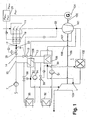
- FIG. 1 a gas turbine group is shown, which in a known manner a compressor 101, a combustion chamber 102, a turbine 103, and a generator 104 includes.
- the turbine drives the compressor and the generator via a shaft 105.
- the shown gas turbine group furthermore has an injection and atomization device 11 for a liquid, in particular water, arranged upstream of the compressor inlet.
- a liquid in particular water
- some of the liquid sprayed as droplet mist is still evaporated in the intake duct, whereby the compressor intake air is cooled, resulting in an increase in the density of the intake air and the delivered mass flow.
- liquid droplets entering the compressor continue to provide intense internal cooling in the compressor, which consequently absorbs less power so that more of the turbine power is available to drive the generator.
- a pump 7 delivers the pressurized demineralized liquid mass flow via the inflow line 14 to the atomizing device 11.
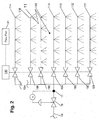
- the injection device 11 includes a plurality of nozzle pipes 111 to 11n. These are selectively switched on and off via shut-off elements 191 to 19n.
- Each nozzle tube 111 to 11n carries a number of non-individually illustrated, but familiar to the expert atomizer nozzles. In the case of Druckzerstäuberdüsen the fineness of the generated liquid mist is significantly dependent on the atomization pre-pressure.
- a pressure regulating valve 18 is arranged. This opens and closes in dependence on a pressure determined at the pressure measuring point 17 in order to keep it constant.
- a function block 21 detects the actual power P ACT of the generator and a power setpoint P set and forms therefrom the setpoint actual deviation P setpoint - P ACT .
- the desired-actual value deviation is forwarded to a control unit 190.
- at least one of the shut-off elements 191, 192,..., 19n is selectively opened.
- a nozzle tube is additionally acted upon with liquid, and increased at constant pre-pressure of the injected liquid mass flow.
- the actuator 18 is designed to keep the atomizing pre-pressure constant, or at least to keep within a setpoint range.
- the actuator 19, in this case a valve group, controls the mass flow of the liquid to be injected.
- the control of the mass flow and the liquid admission pressure are advantageously decoupled from each other.
- a temperature measuring point 22 located upstream of the compressor 101 and downstream of the atomizing device 11 a temperature of the moist air or of the air-droplet mixture in the inflow channel upstream of the compressor inlet is measured. Within certain thermodynamic limits, it is possible to control or regulate the temperature at the measuring point 22 by varying the temperature of the atomizing liquid.
- a heat supply device for a partial flow of the atomizing liquid as a heat exchanger, which, for example, in the exhaust gas flow of a Heat engine is arranged, or is in thermal communication with cooling units.
- the heat exchanger can be readily arranged in the cooling circuit of a diesel engine, or absorb heat from lube oil coolers, or, as explained below, be connected to cooling air coolers of a gas turbine group.
- the illustrated gas turbine group has a two-stage cooling air system.
- a high pressure cooling air path 106 branches out of the compressed air flow path downstream of the compressor 101 and supplies air to the combustion chamber pressure level.
- a low pressure cooling air path 107 branches off within the compressor, leading cooling air of a lower pressure level. With the high-pressure cooling air, the combustion chamber 102 and a first part of the turbine 103 are cooled; the low-pressure cooling air flows into the turbine downstream of a first expansion section.
- multistage cooling air systems are very complex, they are used for reasons of the necessary lossy cooling air throttling in gas turbine groups with high pressure ratios.
- both cooling air paths include cooling air coolers 108 and 109, in which heat is removed from the cooling air.
- the temperature of the cooling air flowing to the high-temperature cooling air cooler in modern gas turbine groups under full load conditions is readily in the range of over 400 ° C to well above 500 ° C, which illustrates the useful caloric potentials.
- a partial flow of the pumped by the pump 7 liquid is increasing in the direction
- the cooling air coolers are arranged in the flow path of the liquid downstream of the pump 7; the liquid pressure at this point is typically about 30 to well above 100 bar, in particular 100 to 150 bar. Therefore, a large amount of heat can be supplied without causing boiling of the liquid, which simplifies the structure of the heat exchanger apparatuses 108 and 109.
- the heated liquid flows via a line 13 with an actuator 12 to a common supply line 14. In this case, mixing takes place via a bypass line 15 brought up unheated fluid.
- a Mischvor lockerr can be arranged, such that the heat exchanger 108 would be designed as an evaporator, and in the line 13 heating steam would be passed to the guided over the bypass line liquid ,
- a temperature measuring point 22 is arranged in the inflow channel of the gas turbine group. The temperature measured there serves as a controlled variable for a control loop.
- the manipulated variable of the control circuit is the position of the actuator 12.
- the actuator 12 When the measured temperature increases, the actuator 12 is closed and the proportion of heated liquid is reduced, and when the measured temperature decreases, the actuator is opened and the proportion of heated liquid increases. This results in temperature changes of the temperature of the sputtering liquid, which is injected into the sputtering device 11 in the inflow channel, and thus the temperature in the inflow channel is influenced. Furthermore, a temperature measuring point 23 for measuring the temperature of the atomizing liquid is arranged downstream of the merging of the line 13 for the heated liquid and the bypass line 15. If this exceeds a certain upper limit, the actuator 12 is closed.
- actuators 33 and 36 are arranged, the opening of which is controlled in dependence on measured at measuring points 30 and 37 temperatures of the cooled cooling air.
- the actuator of the respective recirculation loop is opened, whereupon the recirculated mass flow increases and the temperature decreases.
- the cooling air temperature can be adjusted to a desired value; Heat which does not dissipate the sputtering liquid is dissipated in the coolers 32 and 35.
- the heat generated in the coolers 32 and 35 can be dissipated in a cooling tower, or used in a manner not relevant to the invention, for example, for efficiency-increasing fuel preheating.
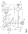
- FIG. 3 A second power plant operated according to the invention is known in FIG. 3 shown.
- the gas turbine group 1 is in conjunction with FIG. 1 described.
- the sputtering device 11 is operated here with flash atomization. That is, the sputtering liquid exits at a temperature above its boiling point at ambient temperature Nebulizer nozzles off.
- the temperature of water here is for example about 120 ° C to 300 ° C, in particular 150 ° C to 200 ° C. Due to the expansion at the nozzle outlet, spontaneous boiling of the liquid begins and the primary droplets produced at the nozzle outlet burst into small fragments.
- the flash atomization is in WO 9967519 been described. Accordingly, the atomization pre-pressure and the atomizing liquid temperature are decisive for the droplets produced.
- the sacreddüsende liquid is conveyed by the pump 7 through an exhaust gas heat exchanger 40 and heated in heat exchange with the exhaust gas of the gas turbine group.
- the liquid flows from the exhaust gas heat exchanger 40 and the line 13 to the actuator 12 and the pressure control unit 17, 18 to the in conjunction with FIG. 2 described sputtering device.
- the heat exchanger 40 is bypassed by a bypass line 15. Upstream of the pressure control valve 18 open the line 13 and the bypass line 15 in a common supply line.
- the temperature of the mixture of heated and unheated fluid is measured.
- the actuator 12 is controlled, and thus the mass flow rates of the preheated and Vietnamesevorgeracermten fluid are changed.
- the actuator 12 is closed.
- the heated mass flow rate decreases, and subsequently the temperature of the atomizing liquid.
- the actuator is opened when the measured temperature decreases. In this way, the temperature can be adjusted in a simple manner to a desired value, for which purpose, of course, a desired-actual-value comparison of the temperature is not shown, but familiar to those skilled in the art.
- a two-point control for setting the temperature can be implemented within a setpoint interval.
- An increase in the temperature of the atomizing liquid of course also to an increase in temperature in the inflow channel of the compressor 101. This temperature is limited to an allowable maximum value. Therefore, the temperature is measured at the measuring point 22, and used as a controlled variable of a limit control. If the permissible maximum temperature value is reached or exceeded, the actuator 12 is closed in the sense of a safety circuit, and optionally further measures initiated.
- gas turbine group has a steam injection into the combustion chamber 102.
- Steam injection via burner lances is well known, for example for nitrogen oxide minimization.
- Water is pumped by the pump 7 to a heat recovery steam generator 40 and evaporated there.
- a portion of the generated steam is injected via a mass flow control line, comprising an actuator 8 and a mass flow measuring point 10, in a known manner in the combustion chamber 102.
- injection downstream of the combustor 102 and upstream of the turbine 103 is known in the art.
- the criteria according to which the mass flow setpoint is determined, for example, as a function of the generator power P ACT and a fuel quantity, are adequately described elsewhere; more detailed explanations would go beyond the frame set here quite decidedly.
- a bypass line 15 branches off, which passes pressurized, unheated water to a mixing preheater 9. Downstream of the steam generator 40 branches off a line 13, which conducts a partial flow of the generated steam as a heating medium to the mixing preheater 9. Heated liquid flows via the supply line 14 in the manner described above to the sputtering device 11. The temperature of the sputtering liquid is determined at the measuring point 23, and adjusted to a desired value.
- a bypass actuator 16 is arranged both in the bypass line 15, and in the steam line 13, a heating steam control valve 12 is arranged. When the temperature of the atomizing liquid exceeds the set value, the bypass actuator 16 is opened and the heating steam control valve 12 is closed.
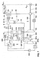
- power plant is a combined plant, and includes next to the gas turbine group 1 a water-steam cycle 2.
- the known per se water-steam cycle 2 includes a heat recovery steam generator 210, which in turn a preheater 211, an evaporator 212, a superheater 213, and a steam drum 214 and a circulation pump 215 for the evaporator.
- the heat recovery steam generator is flowed through in a well-known manner by the exhaust gases of the gas turbine group, and uses their residual heat to generate steam.
- the mode of operation of the water-steam cycle is likewise familiar to a person skilled in the art.
- the steam generated is fed via the live steam control valve 220 to a steam turbine 201 and is decompressed there to drive a generator 202.
- the live steam control valve is controlled in a known manner by a steam turbine power controller, not shown.
- the expanded vapor is passed into a condenser 203 and condensed there.
- the condensate which is present as a function of the condenser temperature at a pressure of about 30-50 mbar, is conveyed by a condensate pump 205 into the feedwater tank 204, which, as explained below, in this case simultaneously serves as a degasser.
- the boiler feed pump 217 conveys the condensate, which typically has a pressure in the feedwater tank in the range from 2 to 5 bar, to the live steam pressure and into the steam generator, which, as is also familiar to the person skilled in the art, is flowed through in the sequence preheater, evaporator, superheater with which the cycle is closed. Numerous modifications of the circuit shown are familiar to the person skilled in the art, which, however, is not essential to the invention in detail. In the present case, a partially relaxed steam mass flow 207 is taken from the steam turbine and as Degassing medium fed to the feedwater tank 204.
- the feedwater tank also has a level control, which is able to compensate for water loss due to unavoidable leaks or degassing of the condensate.
- the level measurement controls an inlet valve 206, which controls the supply of make-up water from a water treatment plant 216.
- the level control can be continuous or in the sense of a two-point control. In the flow path of the steam generator, in this case in the preheater 211, branches off a branch line 13 from the water-steam cycle, is passed through the heated liquid to the atomizing device 11.
- Both branch lines 13 and 15 open into a common supply line 14 to the sputtering device 11.
- the mixing of preheated and not preheated medium thus takes place upstream of the sputtering device, which makes this embodiment particularly in connection with not Hilfsiendienunterorganizen atomizers advantageous.
- Actuators 12 and 16 allow adjustment of the relative mass flow rates of the non-preheated liquid in the bypass line 15 and the preheated liquid in the conduit 13, and thus an adjustment of the temperature of the liquid in the supply line 14.
- a temperature measuring point 22 is arranged, which determines the temperature of the moist air or the air-drop mixture. Due to the evaporation effect and the acceleration of the flow towards the compressor inlet, the temperature at this point can be considerably lower than the ambient temperature.
- the actuators 12 and 16 are actuated. However, this regulates only the mass flow conditions of preheated and not preheated fluid; the total mass flow will continue to be as described above Way controlled by the shut-off valves 19 and the controller 21 in response to the net power of the gas turbine group. In a first operating state, the actuator 12 is completely closed.
- the entire mass flow of the sputtering device 11 is passed through the first bypass line 15 without heating.
- a maximum cooling of the intake air of the gas turbine group is achieved because the injected liquid has the lowest possible temperature.
- the actuator 12 is opened a piece, and actuator 16 a piece closed.
- a portion of the water to be injected flows through the preheater 211 of the steam generator 210 and is heated there. The temperature of the water to be injected is thus increased, and as a consequence, the temperature at the compressor inlet also increases.
- a further temperature measuring point 23 is arranged upstream of the atomizing device and downstream of the combination of the preheated and the non-preheated liquid. If the atomization temperature measured there falls below a certain safety margin of, for example, 5 ° C. or 8 ° C. to the boiling point of the liquid at ambient pressure, the actuator 12 is closed. At sea level and operating with water, the critical temperature reading is, for example, in the range of 90 ° C to 95 ° C, in lower-altitude installations correspondingly lower. Although this limit control can lead to operating restrictions, but prevents serious cavitation damage that would occur to not specially prepared injection nozzles of the sputtering device 11, when the liquid spontaneously boils on exiting the nozzle.
- the temperature control described is of interest in gas turbine groups, which are installed in locations where no so-called anti-icing system familiar to the person skilled in the art is required, but where the fogging or high fogging operation can cause it to fall below the ice formation temperature.
- the temperature increase achievable in this way is of course limited.
- a absolute temperature increase of the air can be realized if the mass flow of the liquid, which are carried as drops, is many times greater than the evaporated liquid mass flow, so that the additionally introduced sensible heat exceeds the heat of evaporation.
- the ambient temperature range in which a fogging or high fogging installation can be operated can be significantly expanded.
- the liquid mass flow to be injected in the atomizing device 11 is provided by the water treatment plant 216.
- the sputtering device can also be operated as a "genuine" anti-icing system.
- the mass flow control must be decoupled from the power control, and the mass flow must be operated with the measured value of the measuring point 22 as a controlled variable.
- an absolute temperature increase is only possible if in fact so much heated liquid is injected, that the air is supersaturated at the compressor inlet, so enter into the compressor with drops. In this way, in installations that do not require an anti-icing per se or only a few days a year, the operation can be ensured without having to specially arrange a complex anti-icing device.
- the embodiment according to FIG. 6 is different from the one in FIG. 5 Example shown, inter alia, that the bypass line 15 and the second line 13 do not open directly into the supply line 14, but in a mixing preheater 9, which in turn has an orifice in the supply line 14.
- the bypass line 15 guided water is mixed in the mixing preheater 9 with a removed in the heat recovery steam generator 210 and via a branch line and the actuator 12 guided heating medium and heated it.
- the heating medium is removed in the example shown as superheated steam in the superheater 213.
- This embodiment proves to be particularly suitable when a significant temperature increase is required for flash atomization, because the mass flow of heating media can be comparatively low.
- the branch line to the steam drum 214 for the removal of saturated steam or saturated water.
- Another possible embodiment is characterized in that in the evaporator 212 boiling water or a boiling water saturated steam mixture is removed.
- heated water is removed from the preheater 211 as the heating medium. The selection of the sampling point is ultimately to be made by a specialist with the aid of his expertise and under consideration of the thermodynamic boundary conditions. The exemplified use of energetically high-quality steam as the heating medium allows a large increase in temperature with a low mass flow of heating medium.
- the embodiment according to FIG. 7 characterized on the one hand by the fact that the temperature of the atomizing liquid, measuring point 23, is used as a controlled variable, with a limit control of the temperature in the inflow channel, measuring point 22 is implemented, in the sense of limiting the temperature measured there to a maximum value.
- the embodiment according to FIG. 7 is used as the heating medium bleed steam from the steam turbine.
- the mixing preheater 9 must be arranged downstream of the pressure control valve 18, and the pressure must be adjusted to a value which is below the pressure at the tapping point of the water-steam cycle. In a large number of cases, it will not be economical to specifically arrange a tapping point on the steam turbine. It is therefore shown a water-steam cycle with reheat.
- the steam turbine consists of a high pressure steam turbine 201 a and a medium / low pressure steam turbine 201 b.
- Fresh steam from the superheater 213 is expanded in the high-pressure turbine 201 a to about saturated steam state, and then brought back to fresh steam temperature in a reheater 218 and relaxed in the medium / low pressure turbine 201 b to condenser pressure. It can be particularly easy in the region of the reheater 218 connect the steam line 13. In this case, saturated steam is taken at the outlet from the high-pressure turbine 201a, as shown, or superheated steam at the inlet to the medium / low-pressure turbine 201 b.
- the branch line 13 can also connect to the reheater 218, but an access to the heat recovery steam generator is more complex in terms of apparatus than a connection to inlet and outlet lines located outside the steam generator.
- FIG. 8 embodiment shown has a two-pressure water-steam cycle, wherein the heat recovery steam generator is designed as a two-pressure single-pass boiler.
- a high-pressure branch branches with the high-pressure feed pump 221 and the high-pressure steam generator bore 222 as well as a medium / low-pressure branch with the medium / low-pressure feed pump 223 and the medium / low-pressure steam generator bore 224 from.
- the high-pressure steam generated is expanded over the entire steam turbine 201, while the medium / low-pressure branch opens at an intermediate feed, located farther downstream of the steam turbine, at a point of adapted pressure.
- This circuit variant of a water-steam cycle is familiar to those skilled in the art, and therefore requires no further explanation.
- a branch line 13 branches off downstream of the boiler from the middle / low-pressure bathtechnikerberohrung. Likewise, the diversion could in principle also be arranged inside the boiler. The illustrated variant is generally much easier to realize because no access to the boiler must be created. It is quite possible that a branch line immediately downstream the condensate pump 205 branches off from the water-steam circuit when the prevailing pressure is compatible with the required liquid pressure of the atomizing device; This is the case, for example, when using auxiliary-assisted atomizers, where no high liquid pre-pressure is required. Of course, a line branching off there could also be led via a separate heat exchanger arranged in the region of the waste heat steam generator.
- the line 13 leads via the actuator 12 a controllable mass flow superheated steam as a heating medium for Mischvor Anlagenr 9. From the Mischvor lockerr 9 preheated water flows into the supply line 14. Furthermore, in the embodiment according to FIG. 8 arranged in the liquid line 14, a radiator 24. The coolant flow to the radiator 24 and thus its cooling capacity is controlled by the actuator 25. In the interaction of the actuators 12 and 16, it is possible, as stated above, to regulate the temperature detected in the inflow channel by means of the temperature measuring point 22 before the entry of the compressor to a desired value or into a desired value interval or to a minimum value. It is also possible, at least within certain limits, to lower the temperature in the inflow channel by cooling the liquid in the cooler 24.
- the temperature at the measuring point 22 it is therefore possible, for example, to regulate the temperature at the measuring point 22 to a value as low as possible above the temperature in the compressor inlet starting ice formation. Limits are set by the fact that the temperature at the measuring point 23 must always remain above the freezing temperature of the liquid. For pure water, the additional intake air cooling by precooling the liquid to be atomized quite narrow limits.
- One measure is the metered addition of alcohols or other suitable antifreeze additives upstream of the cooler.
- an additive tank 26 is arranged, from which a suitable additive can be admixed via a pump 27, a shut-off valve 29, as well as an actuator 28 of the atomizing liquid upstream of the radiator 24 if necessary.
- the obturator 29 is opened.
- the actuator 28 is controlled so that the promoted additive mass flow increases with decreasing temperature according to a given additive concentration-temperature profile. It is possible in this way to achieve a maximum allowable cooling of the air at the compressor inlet with simultaneous supersaturation of the air with moisture and the resulting internal cooling effect in the compressor. This can maximize the net power output of the gas turbo group available to drive the generator.
Landscapes
- Engineering & Computer Science (AREA)
- Chemical & Material Sciences (AREA)
- Combustion & Propulsion (AREA)
- Mechanical Engineering (AREA)
- General Engineering & Computer Science (AREA)
- Engine Equipment That Uses Special Cycles (AREA)
- Nozzles (AREA)
Claims (28)
- Procédé de conduite d'une centrale électrique comprenant
une machine de combustion (1) consommant de l'air et dotée d'une admission d'air et d'un canal d'amenée disposé en amont de l'admission d'air, ainsi que
un ensemble (11) de pulvérisation disposé dans le canal d'amenée,
un liquide étant dans le procédé injecté dans l'ensemble de pulvérisation situé dans le canal d'amenée,
le procédé comportant les étapes supplémentaires qui consistent à :mesurer au moins l'une des températures suivantes : température du liquide de pulvérisation à injecter en amont de l'ensemble de pulvérisation ou température régnant dans le canal d'amenée en aval de l'ensemble de pulvérisation etfaire intervenir l'une desdites températures comme grandeur de régulation,caractérisé par l'étape qui consiste à :commander la température du liquide de pulvérisation en fonction de la grandeur de régulation. - Procédé selon la revendication 1, caractérisé en ce que la température du liquide de pulvérisation est régulée à l'intérieur d'un intervalle de valeurs de consigne ou à une valeur de consigne constante.
- Procédé selon la revendication 2, caractérisé en ce qu'une température du liquide de pulvérisation est régulée à une température située au-dessus du point d'ébullition à pression ambiante.
- Procédé selon l'une des revendications 2 ou 3, caractérisé par les étapes qui consistent à :déterminer la température qui règne dans le canal d'amenée en aval de l'ensemble de pulvérisation,interrompre l'injection de liquide si une valeur minimale admissible de la température qui règne dans le canal d'amenée n'est pas atteinte etinterrompre l'injection de liquide si une valeur maximale admissible de la température dans le canal d'amenée est dépassée.
- Procédé selon la revendication 1, caractérisé par les étapes qui consistent à :augmenter la température du liquide de pulvérisation si une valeur de consigne ou une valeur de seuil inférieure de la température qui règne dans le canal d'amenée n'est pas atteinte etabaisser la température du liquide de pulvérisation lorsqu'une valeur de consigne ou une valeur de seuil supérieure de la température qui règne dans le canal d'écoulement est dépassée.
- Procédé selon la revendication 1, caractérisé par l'étape qui consiste à augmenter la température du liquide de pulvérisation si une température limite inférieure n'est pas atteinte dans le canal d'écoulement.
- Procédé selon l'une des revendications 5 ou 6, caractérisé par l'étape qui consiste à limiter la température du liquide de pulvérisation à une valeur maximale.
- Procédé selon la revendication 7, caractérisé par l'étape qui consiste à interrompre l'injection de liquide si une température minimale admissible est atteinte ou n'est pas atteinte dans le canal d'écoulement d'amenée et si en même temps la température maximale admissible du liquide de pulvérisation est atteinte.
- Procédé selon l'une des revendications précédentes, caractérisé par l'étape qui consiste à abaisser la température du liquide de pulvérisation si une température supérieure est atteinte ou dépassée dans le canal d'aspiration.
- Procédé selon l'une des revendications précédentes, caractérisé par l'étape qui consiste à limiter la température du liquide de pulvérisation vers le bas à une valeur minimale.
- Procédé selon la revendication 10, caractérisé par l'étape qui consiste à interrompre l'injection de liquide si une température maximale admissible est dépassée dans le canal d'amenée et si simultanément la température minimale admissible du liquide de pulvérisation est atteinte.
- Procédé selon l'une des revendications précédentes, caractérisé par l'étape qui consiste à mélanger un additif et en particulier un agent de protection contre le gel au liquide de pulvérisation lorsqu'une température de seuil inférieure du liquide de pulvérisation n'est pas atteinte.
- Procédé selon l'une des revendications précédentes, caractérisé par l'étape qui consiste à faire passer au moins un premier écoulement massique partiel de liquide de pulvérisation dans un ensemble (40, 108, 109, 210) d'apport de chaleur.
- Procédé selon la revendication 13, caractérisé par l'étape qui consiste à commander l'apport de chaleur dans l'ensemble d'amenée de chaleur pour commander la température du liquide de pulvérisation.
- Procédé selon l'une des revendications 13 ou 14, caractérisé par les étapes qui consistent à :amener un deuxième écoulement partiel de liquide de pulvérisation par un conduit de dérivation (15),rassembler avant la pulvérisation le premier écoulement partiel et le deuxième écoulement partiel etpour commander la température du liquide de pulvérisation, commander de manière variable au moins l'un des écoulements partiels.
- Procédé selon la revendication 15, caractérisé en ce que la température du liquide de pulvérisation est mesurée en aval de l'emplacement de rassemblement des écoulements partiels.
- Procédé selon l'une des revendications 15 ou 16, caractérisé par les étapes qui consistent à :vaporiser le premier écoulement partiel dans l'agent d'amenée de chaleur etrassembler le premier écoulement partiel et le deuxième écoulement partiel dans un préchauffeur-mélangeur (9).
- Procédé selon l'une des revendications 13 à 17, caractérisé par l'étape qui consiste à transporter le premier écoulement partiel, avant son introduction dans l'ensemble d'apport de chaleur, à une pression qui correspond au moins à la pré-pression du liquide de l'ensemble de pulvérisation.
- Procédé selon l'une des revendications 15 à 18, caractérisé par les étapes qui consistent à :amener un écoulement massique de liquide à travers un échangeur de chaleur de gaz d'échappement (40) de la machine motrice,ramener le premier écoulement massique partiel au moins à travers une partie du parcours d'écoulement de 1'échangeur de chaleur de gaz d'échappement etdériver le deuxième écoulement partiel en amont de l'échangeur de chaleur de gaz d'échappement.
- Procédé selon l'une des revendications précédentes, caractérisé par les étapes qui consistent à :amener au moins une partie du liquide de pulvérisation à travers un refroidisseur (24) avant la pulvérisation etcommander la puissance de refroidissement du refroidisseur pour commander la température du liquide de pulvérisation.
- Procédé selon l'une des revendications précédentes, caractérisé en ce que la pulvérisation du liquide s'effectue comme pulvérisation sous pression, la pression de pulvérisation du liquide de pulvérisation dépassant de préférence 20 bars.
- Installation de centrale électrique en vue de la mise en oeuvre du procédé selon l'une des revendications précédentes, la machine motrice à combustion comprenant un groupe (1) de turbine à gaz, l'admission d'air étant l'admission d'air du compresseur du groupe (1) de turbine à gaz, le groupe (1) de turbine à gaz comprenant au moins un compresseur (101), une chambre de combustion (102), une turbine (103), un générateur (104), un ensemble de pulvérisation (11) pour un liquide et un dispositif (40, 108, 109, 210) d'amenée de chaleur qui chauffe le liquide à pulvériser,
le dispositif (40, 108, 109, 210) d'amenée de chaleur étant un générateur de chaleur doté d'un échangeur de chaleur. - Installation de centrale électrique selon la revendication 22, caractérisée en ce que le dispositif d'amenée de chaleur est couplé thermiquement à un circuit de refroidissement d'une machine motrice thermique.
- Installation de centrale électrique selon la revendication 22, caractérisée en ce que le dispositif d'amenée de chaleur est un refroidisseur (108, 109) d'air de refroidissement du groupe (1) de turbine à gaz.
- Installation de centrale électrique selon la revendication 22, caractérisée par un premier parcours d'écoulement (13) qui conduit à travers le dispositif (40, 108, 109, 210) d'amenée de chaleur, un deuxième parcours d'écoulement (15) qui contourne le dispositif (40, 108, 109, 210) d'amenée de chaleur ainsi qu'un conduit (14) d'amenée de liquide de pulvérisation, les deux parcours d'écoulement débouchant dans le conduit (14) qui amène à l'ensemble (11) de pulvérisation, un organe d'étranglement ajustable (12, 16) étant disposé dans au moins l'un des parcours d'écoulement (13, 15).
- Installation de centrale électrique selon la revendication 22, caractérisée en ce que le dispositif (40, 108, 109, 210) d'amenée de chaleur est un générateur (210) de vapeur de surchauffe d'un circuit d'eau et de vapeur.
- Installation de centrale électrique selon la revendication 22, caractérisée par un refroidisseur (24) disposé dans le parcours d'écoulement (14) du liquide de pulvérisation, en amont de l'ensemble de pulvérisation (11).
- Installation de centrale électrique selon l'une des revendications 22 à 27, caractérisée en ce que l'ensemble de pulvérisation (11) comporte des tuyères de pulvérisation sous pression.
Applications Claiming Priority (2)
| Application Number | Priority Date | Filing Date | Title |
|---|---|---|---|
| CH18562003 | 2003-10-30 | ||
| PCT/EP2004/052681 WO2005042947A1 (fr) | 2003-10-30 | 2004-10-28 | Procede pour faire fonctionner une centrale electrique |
Publications (2)
| Publication Number | Publication Date |
|---|---|
| EP1704313A1 EP1704313A1 (fr) | 2006-09-27 |
| EP1704313B1 true EP1704313B1 (fr) | 2016-03-30 |
Family
ID=34529361
Family Applications (1)
| Application Number | Title | Priority Date | Filing Date |
|---|---|---|---|
| EP04817390.0A Expired - Lifetime EP1704313B1 (fr) | 2003-10-30 | 2004-10-28 | Procede pour faire fonctionner une centrale electrique |
Country Status (3)
| Country | Link |
|---|---|
| US (1) | US7481060B2 (fr) |
| EP (1) | EP1704313B1 (fr) |
| WO (1) | WO2005042947A1 (fr) |
Families Citing this family (22)
| Publication number | Priority date | Publication date | Assignee | Title |
|---|---|---|---|---|
| DE10333208A1 (de) * | 2003-07-22 | 2005-03-31 | Alstom Technology Ltd | Verfahren zum Betrieb einer luftatmenden Kraftmaschine |
| US7703272B2 (en) * | 2006-09-11 | 2010-04-27 | Gas Turbine Efficiency Sweden Ab | System and method for augmenting turbine power output |
| BE1018906A3 (fr) * | 2006-10-16 | 2011-11-08 | Hitachi Ind Equipment Sys | Compresseur a injection d'eau. |
| US9863646B2 (en) * | 2007-01-26 | 2018-01-09 | David E. Johnson, Jr. | Modulation control of hydronic systems |
| JP2011508139A (ja) * | 2007-12-21 | 2011-03-10 | グリーン パートナーズ テクノロジー ホールディングス ゲゼルシャフト ミット ベシュレンクテル ハフツング | 気化性液体供給装置を採用するガスタービン・システム及び方法 |
| US8463445B2 (en) * | 2010-05-28 | 2013-06-11 | General Electric Company | Method and system for safe drum water level determination in a combined cycle operation |
| EP2623741B1 (fr) * | 2010-09-30 | 2018-11-28 | Mitsubishi Hitachi Power Systems, Ltd. | Installation de production d'électricité à cycle combiné utilisant la chaleur solaire |
| WO2012162533A2 (fr) * | 2011-05-25 | 2012-11-29 | Sam Houston State University | Systèmes de réacteurs à biorémédiation |
| ES2444340B1 (es) | 2012-07-23 | 2014-12-17 | Abengoa Solar New Technologies S.A. | Método de operación de una planta solar termoeléctrica |
| JP6056270B2 (ja) * | 2012-08-28 | 2017-01-11 | ダイキン工業株式会社 | ターボ圧縮機及びターボ冷凍機 |
| US9739476B2 (en) | 2013-11-21 | 2017-08-22 | General Electric Technology Gmbh | Evaporator apparatus and method of operating the same |
| JP6303700B2 (ja) * | 2014-03-28 | 2018-04-04 | 東京電力ホールディングス株式会社 | ガスタービンプラント及びガスタービンプラントの吸気冷却方法 |
| US10557413B1 (en) * | 2014-11-26 | 2020-02-11 | Caldwell Tanks, Inc. | Systems and methods for controlling liquid flow to a turbine fogging array |
| CN104697238B (zh) * | 2015-02-12 | 2017-01-11 | 清华大学 | 适于主动配电网的蓄能型热电冷联供装置及其运行方法 |
| EP3320146B1 (fr) * | 2016-03-07 | 2021-06-16 | Astec Industries, Inc. | Séchoir d'agrégats avec système d'extinction d'échappement |
| KR101953963B1 (ko) * | 2017-01-24 | 2019-03-04 | 두산중공업 주식회사 | 가스터빈 |
| SE542760C2 (en) * | 2018-12-14 | 2020-07-07 | Climeon Ab | Method and controller for preventing formation of droplets in a heat exchanger |
| JP7288413B2 (ja) * | 2020-02-28 | 2023-06-07 | 株式会社東芝 | 発電プラントの蒸気冷却制御システムおよび発電プラントの蒸気冷却設備 |
| CN118831339A (zh) * | 2023-04-24 | 2024-10-25 | 乔治洛德方法研究和开发液化空气有限公司 | 雾化装置、雾化方法及空分设备 |
| CN116771511B (zh) * | 2023-07-04 | 2025-12-05 | 中国航发沈阳发动机研究所 | 一种航空发动机射流预冷系统水流量的控制方法 |
| CN117052539B (zh) * | 2023-08-10 | 2025-09-02 | 中国航发沈阳发动机研究所 | 一种提升射流预冷控制系统温度控制效果的方法 |
| CN117869069B (zh) * | 2024-03-13 | 2024-07-12 | 济南中科先行燃气轮机科技有限公司 | 一种燃气轮机余热利用的闪蒸空气雾化系统及控制方法 |
Family Cites Families (11)
| Publication number | Priority date | Publication date | Assignee | Title |
|---|---|---|---|---|
| DE2549790A1 (de) | 1975-11-06 | 1977-05-18 | Bundesrep Deutschland | Vorrichtung zur kurzzeitigen leistungssteigerung von tragfluegelboot-gasturbinen |
| US5353585A (en) * | 1992-03-03 | 1994-10-11 | Michael Munk | Controlled fog injection for internal combustion system |
| US5463873A (en) * | 1993-12-06 | 1995-11-07 | Cool Fog Systems, Inc. | Method and apparatus for evaporative cooling of air leading to a gas turbine engine |
| JP2877098B2 (ja) | 1995-12-28 | 1999-03-31 | 株式会社日立製作所 | ガスタービン,コンバインドサイクルプラント及び圧縮機 |
| US5867977A (en) | 1996-05-14 | 1999-02-09 | The Dow Chemical Company | Method and apparatus for achieving power augmentation in gas turbines via wet compression |
| SG104914A1 (en) * | 1997-06-30 | 2004-07-30 | Hitachi Ltd | Gas turbine |
| NL1011383C2 (nl) | 1998-06-24 | 1999-12-27 | Kema Nv | Inrichting voor het comprimeren van een gasvormig medium en systemen die een dergelijke inrichting omvatten. |
| US6250064B1 (en) * | 1999-05-07 | 2001-06-26 | General Electric Co. | Gas turbine inlet air integrated water saturation and supersaturation system and related process |
| US6478289B1 (en) * | 2000-11-06 | 2002-11-12 | General Electric Company | Apparatus and methods for controlling the supply of water mist to a gas-turbine compressor |
| US6715916B2 (en) * | 2001-02-08 | 2004-04-06 | General Electric Company | System and method for determining gas turbine firing and combustion reference temperatures having correction for water content in fuel |
| EP1474595B1 (fr) * | 2002-01-07 | 2007-03-14 | ALSTOM Technology Ltd | Mode de fonctionnement d'un groupe a turbine a gaz |
-
2004
- 2004-10-28 WO PCT/EP2004/052681 patent/WO2005042947A1/fr not_active Ceased
- 2004-10-28 EP EP04817390.0A patent/EP1704313B1/fr not_active Expired - Lifetime
-
2006
- 2006-04-27 US US11/411,850 patent/US7481060B2/en not_active Expired - Fee Related
Also Published As
| Publication number | Publication date |
|---|---|
| US7481060B2 (en) | 2009-01-27 |
| EP1704313A1 (fr) | 2006-09-27 |
| US20060248897A1 (en) | 2006-11-09 |
| WO2005042947A1 (fr) | 2005-05-12 |
Similar Documents
| Publication | Publication Date | Title |
|---|---|---|
| EP1682750B1 (fr) | Centrale electrique | |
| WO2005042947A1 (fr) | Procede pour faire fonctionner une centrale electrique | |
| DE10041413B4 (de) | Verfahren zum Betrieb einer Kraftwerksanlage | |
| DE102012011294B4 (de) | Verfahren zum Kühlen einer Gasturbinenanlage sowie Gasturbinenanlage zur Durchführung des Verfahrens | |
| EP1442203B1 (fr) | Procede de regulation des debits massiques d'air de refroidissement d'un ensemble turbine a gaz | |
| EP1474595B1 (fr) | Mode de fonctionnement d'un groupe a turbine a gaz | |
| EP1440223B2 (fr) | Ensemble turbine a gaz | |
| DE602004011762T2 (de) | Verfahren zum betrieb einer gasturbinengruppe | |
| EP1288761B1 (fr) | Procédé de régulation d'un système de bipasse basse pression | |
| EP0591163B2 (fr) | Installation combinee a turbines a gaz et a vapeur | |
| EP1390606B2 (fr) | Dispositif de refroidissement du fluide de refroidissement d'une turbine a gaz et ensemble turbine a gaz et turbine a vapeur comportant un tel dispositif | |
| CH697746A2 (de) | Kombikraftwerk mit einer Vorrichtung für die Druckzufuhr an eine Sprühnebel-Einlasstemperaturreduktion von Gasturbinen sowie Verfahren zu dessen Betrieb. | |
| EP0779423A2 (fr) | Refroidisseur à trempe | |
| DE202007017723U1 (de) | Anlage für die Kälte-, Heiz- oder Klimatechnik, insbesondere Kälteanlage | |
| WO2003024559A1 (fr) | Procede et dispositif de degazage thermique | |
| WO2012034876A2 (fr) | Procédé de régulation d'une augmentation de puissance à court terme d'une turbine à vapeur | |
| CH497664A (de) | Hochdruck-Dampfkraftanlage | |
| DE2752283B1 (de) | Brennkraftmaschinen Anlage | |
| EP1801363A1 (fr) | Centrale électrique | |
| CH626426A5 (en) | Internal combustion engine system with a pressure-charged, water-cooled engine | |
| DE102004051260A1 (de) | Gasturbogruppe | |
| DE10205972A1 (de) | Verfahren zum Betrieb einer Gasturbogruppe | |
| DE69232521T2 (de) | Cheng-zweistoffwärmekraftmaschine und verfahren zum ihren betrieb | |
| DE102020007756A1 (de) | Kühlvorrichtung zum Kühlen von Ladeluft | |
| DE102004014151A1 (de) | Wärmekraftanlage und Verfahren zum Betrieb |
Legal Events
| Date | Code | Title | Description |
|---|---|---|---|
| PUAI | Public reference made under article 153(3) epc to a published international application that has entered the european phase |
Free format text: ORIGINAL CODE: 0009012 |
|
| 17P | Request for examination filed |
Effective date: 20060803 |
|
| AK | Designated contracting states |
Kind code of ref document: A1 Designated state(s): AT BE BG CH CY CZ DE DK EE ES FI FR GB GR HU IE IT LI LU MC NL PL PT RO SE SI SK TR |
|
| 17Q | First examination report despatched |
Effective date: 20061207 |
|
| DAX | Request for extension of the european patent (deleted) | ||
| GRAP | Despatch of communication of intention to grant a patent |
Free format text: ORIGINAL CODE: EPIDOSNIGR1 |
|
| INTG | Intention to grant announced |
Effective date: 20151123 |
|
| GRAS | Grant fee paid |
Free format text: ORIGINAL CODE: EPIDOSNIGR3 |
|
| GRAA | (expected) grant |
Free format text: ORIGINAL CODE: 0009210 |
|
| AK | Designated contracting states |
Kind code of ref document: B1 Designated state(s): AT BE BG CH CY CZ DE DK EE ES FI FR GB GR HU IE IT LI LU MC NL PL PT RO SE SI SK TR |
|
| REG | Reference to a national code |
Ref country code: DE Ref legal event code: R081 Ref document number: 502004015155 Country of ref document: DE Owner name: GENERAL ELECTRIC TECHNOLOGY GMBH, CH Free format text: FORMER OWNER: ALSTOM TECHNOLOGY LTD., BADEN, CH Ref country code: GB Ref legal event code: FG4D Free format text: NOT ENGLISH Ref country code: DE Ref legal event code: R081 Ref document number: 502004015155 Country of ref document: DE Owner name: ANSALDO ENERGIA IP UK LIMITED, GB Free format text: FORMER OWNER: ALSTOM TECHNOLOGY LTD., BADEN, CH |
|
| REG | Reference to a national code |
Ref country code: CH Ref legal event code: EP |
|
| REG | Reference to a national code |
Ref country code: AT Ref legal event code: REF Ref document number: 785670 Country of ref document: AT Kind code of ref document: T Effective date: 20160415 |
|
| REG | Reference to a national code |
Ref country code: IE Ref legal event code: FG4D Free format text: LANGUAGE OF EP DOCUMENT: GERMAN |
|
| REG | Reference to a national code |
Ref country code: DE Ref legal event code: R096 Ref document number: 502004015155 Country of ref document: DE |
|
| PG25 | Lapsed in a contracting state [announced via postgrant information from national office to epo] |
Ref country code: FI Free format text: LAPSE BECAUSE OF FAILURE TO SUBMIT A TRANSLATION OF THE DESCRIPTION OR TO PAY THE FEE WITHIN THE PRESCRIBED TIME-LIMIT Effective date: 20160330 Ref country code: GR Free format text: LAPSE BECAUSE OF FAILURE TO SUBMIT A TRANSLATION OF THE DESCRIPTION OR TO PAY THE FEE WITHIN THE PRESCRIBED TIME-LIMIT Effective date: 20160701 |
|
| REG | Reference to a national code |
Ref country code: NL Ref legal event code: MP Effective date: 20160330 |
|
| RAP2 | Party data changed (patent owner data changed or rights of a patent transferred) |
Owner name: GENERAL ELECTRIC TECHNOLOGY GMBH |
|
| PG25 | Lapsed in a contracting state [announced via postgrant information from national office to epo] |
Ref country code: SE Free format text: LAPSE BECAUSE OF FAILURE TO SUBMIT A TRANSLATION OF THE DESCRIPTION OR TO PAY THE FEE WITHIN THE PRESCRIBED TIME-LIMIT Effective date: 20160330 |
|
| PG25 | Lapsed in a contracting state [announced via postgrant information from national office to epo] |
Ref country code: NL Free format text: LAPSE BECAUSE OF FAILURE TO SUBMIT A TRANSLATION OF THE DESCRIPTION OR TO PAY THE FEE WITHIN THE PRESCRIBED TIME-LIMIT Effective date: 20160330 |
|
| PG25 | Lapsed in a contracting state [announced via postgrant information from national office to epo] |
Ref country code: EE Free format text: LAPSE BECAUSE OF FAILURE TO SUBMIT A TRANSLATION OF THE DESCRIPTION OR TO PAY THE FEE WITHIN THE PRESCRIBED TIME-LIMIT Effective date: 20160330 Ref country code: PL Free format text: LAPSE BECAUSE OF FAILURE TO SUBMIT A TRANSLATION OF THE DESCRIPTION OR TO PAY THE FEE WITHIN THE PRESCRIBED TIME-LIMIT Effective date: 20160330 |
|
| PG25 | Lapsed in a contracting state [announced via postgrant information from national office to epo] |
Ref country code: RO Free format text: LAPSE BECAUSE OF FAILURE TO SUBMIT A TRANSLATION OF THE DESCRIPTION OR TO PAY THE FEE WITHIN THE PRESCRIBED TIME-LIMIT Effective date: 20160330 Ref country code: ES Free format text: LAPSE BECAUSE OF FAILURE TO SUBMIT A TRANSLATION OF THE DESCRIPTION OR TO PAY THE FEE WITHIN THE PRESCRIBED TIME-LIMIT Effective date: 20160330 Ref country code: SK Free format text: LAPSE BECAUSE OF FAILURE TO SUBMIT A TRANSLATION OF THE DESCRIPTION OR TO PAY THE FEE WITHIN THE PRESCRIBED TIME-LIMIT Effective date: 20160330 Ref country code: CZ Free format text: LAPSE BECAUSE OF FAILURE TO SUBMIT A TRANSLATION OF THE DESCRIPTION OR TO PAY THE FEE WITHIN THE PRESCRIBED TIME-LIMIT Effective date: 20160330 Ref country code: PT Free format text: LAPSE BECAUSE OF FAILURE TO SUBMIT A TRANSLATION OF THE DESCRIPTION OR TO PAY THE FEE WITHIN THE PRESCRIBED TIME-LIMIT Effective date: 20160801 |
|
| REG | Reference to a national code |
Ref country code: DE Ref legal event code: R097 Ref document number: 502004015155 Country of ref document: DE |
|
| PG25 | Lapsed in a contracting state [announced via postgrant information from national office to epo] |
Ref country code: DK Free format text: LAPSE BECAUSE OF FAILURE TO SUBMIT A TRANSLATION OF THE DESCRIPTION OR TO PAY THE FEE WITHIN THE PRESCRIBED TIME-LIMIT Effective date: 20160330 |
|
| PLBE | No opposition filed within time limit |
Free format text: ORIGINAL CODE: 0009261 |
|
| STAA | Information on the status of an ep patent application or granted ep patent |
Free format text: STATUS: NO OPPOSITION FILED WITHIN TIME LIMIT |
|
| PG25 | Lapsed in a contracting state [announced via postgrant information from national office to epo] |
Ref country code: BE Free format text: LAPSE BECAUSE OF NON-PAYMENT OF DUE FEES Effective date: 20161031 |
|
| 26N | No opposition filed |
Effective date: 20170103 |
|
| REG | Reference to a national code |
Ref country code: DE Ref legal event code: R081 Ref document number: 502004015155 Country of ref document: DE Owner name: GENERAL ELECTRIC TECHNOLOGY GMBH, CH Free format text: FORMER OWNER: ALSTOM TECHNOLOGY LTD., BADEN, CH Ref country code: DE Ref legal event code: R081 Ref document number: 502004015155 Country of ref document: DE Owner name: ANSALDO ENERGIA IP UK LIMITED, GB Free format text: FORMER OWNER: ALSTOM TECHNOLOGY LTD., BADEN, CH Ref country code: DE Ref legal event code: R082 Ref document number: 502004015155 Country of ref document: DE Representative=s name: DREISS PATENTANWAELTE PARTG MBB, DE |
|
| PG25 | Lapsed in a contracting state [announced via postgrant information from national office to epo] |
Ref country code: SI Free format text: LAPSE BECAUSE OF FAILURE TO SUBMIT A TRANSLATION OF THE DESCRIPTION OR TO PAY THE FEE WITHIN THE PRESCRIBED TIME-LIMIT Effective date: 20160330 |
|
| REG | Reference to a national code |
Ref country code: CH Ref legal event code: PL |
|
| REG | Reference to a national code |
Ref country code: IE Ref legal event code: MM4A |
|
| REG | Reference to a national code |
Ref country code: FR Ref legal event code: ST Effective date: 20170630 |
|
| PG25 | Lapsed in a contracting state [announced via postgrant information from national office to epo] |
Ref country code: CH Free format text: LAPSE BECAUSE OF NON-PAYMENT OF DUE FEES Effective date: 20161031 Ref country code: LI Free format text: LAPSE BECAUSE OF NON-PAYMENT OF DUE FEES Effective date: 20161031 Ref country code: FR Free format text: LAPSE BECAUSE OF NON-PAYMENT OF DUE FEES Effective date: 20161102 |
|
| PG25 | Lapsed in a contracting state [announced via postgrant information from national office to epo] |
Ref country code: LU Free format text: LAPSE BECAUSE OF NON-PAYMENT OF DUE FEES Effective date: 20161028 |
|
| REG | Reference to a national code |
Ref country code: DE Ref legal event code: R082 Ref document number: 502004015155 Country of ref document: DE Representative=s name: DREISS PATENTANWAELTE PARTG MBB, DE Ref country code: DE Ref legal event code: R081 Ref document number: 502004015155 Country of ref document: DE Owner name: ANSALDO ENERGIA IP UK LIMITED, GB Free format text: FORMER OWNER: GENERAL ELECTRIC TECHNOLOGY GMBH, BADEN, CH |
|
| REG | Reference to a national code |
Ref country code: GB Ref legal event code: 732E Free format text: REGISTERED BETWEEN 20170824 AND 20170830 |
|
| PG25 | Lapsed in a contracting state [announced via postgrant information from national office to epo] |
Ref country code: IE Free format text: LAPSE BECAUSE OF NON-PAYMENT OF DUE FEES Effective date: 20161028 |
|
| REG | Reference to a national code |
Ref country code: BE Ref legal event code: MM Effective date: 20161031 |
|
| REG | Reference to a national code |
Ref country code: AT Ref legal event code: MM01 Ref document number: 785670 Country of ref document: AT Kind code of ref document: T Effective date: 20161028 |
|
| PG25 | Lapsed in a contracting state [announced via postgrant information from national office to epo] |
Ref country code: AT Free format text: LAPSE BECAUSE OF NON-PAYMENT OF DUE FEES Effective date: 20161028 |
|
| PGFP | Annual fee paid to national office [announced via postgrant information from national office to epo] |
Ref country code: GB Payment date: 20171019 Year of fee payment: 14 |
|
| PG25 | Lapsed in a contracting state [announced via postgrant information from national office to epo] |
Ref country code: HU Free format text: LAPSE BECAUSE OF FAILURE TO SUBMIT A TRANSLATION OF THE DESCRIPTION OR TO PAY THE FEE WITHIN THE PRESCRIBED TIME-LIMIT; INVALID AB INITIO Effective date: 20041028 Ref country code: CY Free format text: LAPSE BECAUSE OF FAILURE TO SUBMIT A TRANSLATION OF THE DESCRIPTION OR TO PAY THE FEE WITHIN THE PRESCRIBED TIME-LIMIT Effective date: 20160330 |
|
| PG25 | Lapsed in a contracting state [announced via postgrant information from national office to epo] |
Ref country code: MC Free format text: LAPSE BECAUSE OF FAILURE TO SUBMIT A TRANSLATION OF THE DESCRIPTION OR TO PAY THE FEE WITHIN THE PRESCRIBED TIME-LIMIT Effective date: 20160330 Ref country code: TR Free format text: LAPSE BECAUSE OF FAILURE TO SUBMIT A TRANSLATION OF THE DESCRIPTION OR TO PAY THE FEE WITHIN THE PRESCRIBED TIME-LIMIT Effective date: 20160330 |
|
| PG25 | Lapsed in a contracting state [announced via postgrant information from national office to epo] |
Ref country code: BG Free format text: LAPSE BECAUSE OF FAILURE TO SUBMIT A TRANSLATION OF THE DESCRIPTION OR TO PAY THE FEE WITHIN THE PRESCRIBED TIME-LIMIT Effective date: 20160330 |
|
| PGFP | Annual fee paid to national office [announced via postgrant information from national office to epo] |
Ref country code: DE Payment date: 20181019 Year of fee payment: 15 |
|
| PGFP | Annual fee paid to national office [announced via postgrant information from national office to epo] |
Ref country code: IT Payment date: 20181024 Year of fee payment: 15 |
|
| GBPC | Gb: european patent ceased through non-payment of renewal fee |
Effective date: 20181028 |
|
| PG25 | Lapsed in a contracting state [announced via postgrant information from national office to epo] |
Ref country code: GB Free format text: LAPSE BECAUSE OF NON-PAYMENT OF DUE FEES Effective date: 20181028 |
|
| REG | Reference to a national code |
Ref country code: DE Ref legal event code: R119 Ref document number: 502004015155 Country of ref document: DE |
|
| PG25 | Lapsed in a contracting state [announced via postgrant information from national office to epo] |
Ref country code: DE Free format text: LAPSE BECAUSE OF NON-PAYMENT OF DUE FEES Effective date: 20200501 |
|
| PG25 | Lapsed in a contracting state [announced via postgrant information from national office to epo] |
Ref country code: IT Free format text: LAPSE BECAUSE OF NON-PAYMENT OF DUE FEES Effective date: 20191028 |