EP1704397B1 - Capteur de pression - Google Patents
Capteur de pression Download PDFInfo
- Publication number
- EP1704397B1 EP1704397B1 EP04820819.3A EP04820819A EP1704397B1 EP 1704397 B1 EP1704397 B1 EP 1704397B1 EP 04820819 A EP04820819 A EP 04820819A EP 1704397 B1 EP1704397 B1 EP 1704397B1
- Authority
- EP
- European Patent Office
- Prior art keywords
- membrane
- pressure sensor
- basic body
- opening
- recess
- Prior art date
- Legal status (The legal status is an assumption and is not a legal conclusion. Google has not performed a legal analysis and makes no representation as to the accuracy of the status listed.)
- Expired - Lifetime
Links
Images



Classifications
-
- G—PHYSICS
- G01—MEASURING; TESTING
- G01L—MEASURING FORCE, STRESS, TORQUE, WORK, MECHANICAL POWER, MECHANICAL EFFICIENCY, OR FLUID PRESSURE
- G01L23/00—Devices or apparatus for measuring or indicating or recording rapid changes, such as oscillations, in the pressure of steam, gas, or liquid; Indicators for determining work or energy of steam, internal-combustion, or other fluid-pressure engines from the condition of the working fluid
- G01L23/08—Devices or apparatus for measuring or indicating or recording rapid changes, such as oscillations, in the pressure of steam, gas, or liquid; Indicators for determining work or energy of steam, internal-combustion, or other fluid-pressure engines from the condition of the working fluid operated electrically
- G01L23/18—Devices or apparatus for measuring or indicating or recording rapid changes, such as oscillations, in the pressure of steam, gas, or liquid; Indicators for determining work or energy of steam, internal-combustion, or other fluid-pressure engines from the condition of the working fluid operated electrically by resistance strain gauges
-
- G—PHYSICS
- G01—MEASURING; TESTING
- G01L—MEASURING FORCE, STRESS, TORQUE, WORK, MECHANICAL POWER, MECHANICAL EFFICIENCY, OR FLUID PRESSURE
- G01L23/00—Devices or apparatus for measuring or indicating or recording rapid changes, such as oscillations, in the pressure of steam, gas, or liquid; Indicators for determining work or energy of steam, internal-combustion, or other fluid-pressure engines from the condition of the working fluid
- G01L23/08—Devices or apparatus for measuring or indicating or recording rapid changes, such as oscillations, in the pressure of steam, gas, or liquid; Indicators for determining work or energy of steam, internal-combustion, or other fluid-pressure engines from the condition of the working fluid operated electrically
- G01L23/12—Devices or apparatus for measuring or indicating or recording rapid changes, such as oscillations, in the pressure of steam, gas, or liquid; Indicators for determining work or energy of steam, internal-combustion, or other fluid-pressure engines from the condition of the working fluid operated electrically by changing capacitance or inductance
Definitions
- the invention relates to a pressure sensor, consisting of a membrane which separates the pressure-induced membrane deformation measuring device from the pressurized pressure chamber and the pressure sensor is formed by a base body which is inserted into an opening of the pressure chamber bounding wall.
- the arrangement is chosen so that the membrane parallel to the wall bounding the pressure chamber is oriented.
- the membrane is also arranged unprotected at the end of the sensor projecting into the pressure chamber. This unprotected construction can cause, for example, the membrane to be damaged during installation and then the pressure sensor is unusable.
- the size of the membrane is limited in this variant by the available opening in the pressure chamber, such prior art pressure sensors, for example, are not installed in the cylinder head, since there may be provided only a small opening under certain circumstances, since the remaining space, for example, from inlet - and exhaust valves is occupied.
- the membrane is not oriented parallel to the wall, but preferably at right angles, ie parallel to its surface normal (this is perpendicular to the imaginary in the opening area). This makes it easy to protect the sensitive membrane, for example, to arrange a corresponding housing.
- the housing has a recess in order to bring the membrane into communication with the pressure chamber.
- an inventive pressure sensor is installed in a cylinder-like combustion chamber whose wall is, for example, the lateral surface of the cylinder, or the installation space is spherical (for example in the cylinder head) is formed.
- the opening is not described by a flat surface, but possibly by a corresponding curved surface.
- the opening should be understood as meaning the opening in view and the membrane surface being oriented parallel or at an acute angle to the surface normal of this opening represented by the view.
- the preferred orientation of the membrane is in relation to the installation direction of the pressure sensor in the wall.
- the pressure sensor in the surrounding the pressure chamber body for example, the cylinder wall or the cylinder head, installed, first in the wall is to introduce a corresponding hole.
- This hole is defined by a longitudinal axis, which is usually parallel to the surface normal. Therefore, the installation direction is parallel to the surface normal in the context of this application.
- a particular advantage of the invention lies in the fact that the available membrane area is no longer dependent on the opening in the wall by this inventive arrangement of the membrane.
- the membrane can extend at right angles to the wall and be optimized according to the desired properties. This opens up the possibility of installing the pressure sensor according to the invention, for example in areas where usually only space for a small opening is available and where the known pressure sensors can not be installed due to the required surface or opening.
- the invention therefore combines optimum protection of the sensitive membrane with a very space-saving arrangement of the sensor in the pressure chamber, without having to make the membrane necessarily very small, which is at the expense of accuracy.
- the pressure sensor needs a corresponding access to the pressure chamber whose pressure is to be measured.
- a bore is provided in the wall bounding the pressure chamber into which the pressure sensor is inserted.
- the base body has a membrane recess or membrane opening, in which the membrane is inserted and tightly connected, for example, welded or glued.
- the multi-part variant has corresponding advantages in the production of the pressure sensor. Since it is provided that the membrane carries the pressure-induced membrane deformation measuring device, it is convenient to prepare the membrane as a separate component with the measuring device and then install the membrane into the body, which may serve as a carrier or housing of the membrane. It is also possible to provide the membrane in the multi-part design of a different material as the body. In order to be able to mount the membrane accordingly, a membrane recess or a membrane opening is provided on the base body. The membrane seals the opening, since the membrane is considered a sealing surface between the pressurized and the normal pressure room.
- the arrangement can also be chosen so that a diaphragm recess is provided in the base body and this is closed by the membrane. In this case, for example, the diaphragm would be mounted from the pressurized side, in FIG The area covered by the membrane would then be arranged, for example, the evaluation electronics.
- the pressure sensor has contact lines for connecting the measuring device to a connection area or an evaluation unit.
- the information received by the measuring device is passed through the contact lines to the outside.
- the pressure sensor also comprises an evaluation unit or only one connection area, for example plug contacts and so on, and the evaluation unit is provided away from the sensor.
- an evaluation unit then has a connection area in order to forward the determined data accordingly.
- the contact line is provided on the side facing away from the pressure chamber. According to the invention it is provided that at least one contact line is provided, but conveniently several, for example, four contact lines are arranged in parallel. The proposed position protects the contact lines through the membrane from the pressure prevailing in the pressure chamber.
- the contact line can be designed, for example, cable-like or wire-like or the contact line is designed as a conductor, for example in thin-film technology.
- the membrane is part of a membrane holder and the membrane holder is inserted in particular in the membrane recess and / or membrane opening of the base body.
- the handling in such a variant according to the invention is facilitated since the membrane holder carries the sensitive membrane only within a certain range. Since the membrane has to show a certain mobility, at least only the membrane area is actually exposed to the pressure, the remaining membrane holder is for example full, bed-like embedded in the main body (for example, in the mounting recess), wherein the configuration in the base body is made so that the membrane is a safe support is required and only the area of the membrane holder acts as a membrane, which also cooperates with the corresponding measuring device. It does not necessarily have to be provided a diaphragm recess, but it facilitates the leadership or assembly.
- the arrangement is chosen in a variant according to the invention so that the membrane holder carries contact lines.
- the membrane holder comprises on the one hand the membrane, on the other hand, the membrane holder takes on the task of positioning the membrane at the appropriate location and hold. Furthermore, the membrane holder also takes on the task of providing contact lines, with which the measuring device is connected to the remote from the membrane evaluation unit and so on.
- the basic body is, as already described, significantly larger, since it also fulfills a housing function for the sensor.
- the manufacturing process is significantly cheaper if not the entire pressure sensor, for example, in a thin-film coating process is equipped with the contact lines, but only the membrane holder.
- the coating of the large-volume pressure sensor only in a certain range would be expensive, the coating of only the membrane holder with the contact lines and the measuring device, however, leads to a very high efficiency and significantly better utilization of these complex coating systems.
- the multi-part structure allows the membrane or the membrane holder and the base body can be optimized with respect to their respective functions and properties.
- the membrane holder is elongated and the contact lines preferably run parallel to this elongated extension. This means that the adhesion of corresponding wires or cables for forwarding the information not in the front region in which the membrane is arranged, must be made, as there may occur during operation significant temperature peaks that could damage the cable connection under certain circumstances.
- the membrane is sealed in the body, for example, welded.
- appropriate laser welding methods are used, which make it possible to perform very filigree welds.
- the membrane has to have some flexibility and the welding process should not affect or destroy the functionality of the membrane.
- the pressure sensor consists of a main body to which the membrane is integrally connected or formed.
- the membrane is thereby obtained by a weakening of the material body at a suitable location.
- the advantage of this variant is precisely that is dispensed with a separate component as a membrane and the base body is designed so that a part of the body serves as a membrane. This can be easily achieved by appropriate machining or material detaching processing.
- This variant saves complex assembly and bonding techniques. Also, the one-piece design from the outset is dense and it There is no need for additional efforts here.
- the pressure sensor according to the invention is simply inserted into a bore of the wall bounding the pressure chamber, the pressure sensor can be used as desired.
- the main body is used according to the invention in the wall bounding the pressure chamber.
- the base body has a thread which can be screwed into a bore of the wall.
- the base body conveniently has a corresponding external thread.
- the wall bore may be either a through hole or a blind bore with subsequent opening to the pressure chamber.
- the base body is indirectly used in the wall bounding the base body and that by means of a sleeve receiving the base body.
- the sleeve has an inner and an outer thread. With the external thread, the sleeve is in the bore, this in turn can be a through hole or a blind bore, screwed and with the internal threads of the main body is connected to the sleeve.
- the membrane is machined in one piece from the main body.
- the membrane is a filigree component.
- the quality of the membrane ultimately defines the quality of the pressure sensor.
- a same quality of the pressure sensors can be realized when the membrane in one piece from the body is worked out.
- the proposal saves complex assembly work of the membrane on the membrane carrier. For working out of the membrane by appropriate weakening of the body material consist machining or material detaching machining processes that ensure a sufficiently high quality and reproducibility. In addition to the normal, known machining techniques, corresponding laser processing or laser cutting methods are also known and usable.
- the thread is arranged in the rear region of the base body.
- the location behind refers to the installation direction.
- At the front in this context is the area of the pressure sensor in which the membrane is arranged. It is quite sufficient to equip only a part of the body with a thread and screw it firmly into the wall and secure it accordingly.
- the invention provides that the pressure sensor is inserted in a blind bore of the wall and in the bottom of the blind bore an opening is provided to the pressure chamber.
- Such a configuration is favorable in that the bottom of the blind bore is used for sealing purposes.
- blind hole or blind hole in the wall limiting the pressure chamber it is always meant a blind hole hole with opening in the ground.
- the basic body tapers from the rear to the front.
- the arrangement is chosen so that the diameter of the base body in the rear region, in which the thread is arranged, is greater than in the front region, in which the membrane located.
- the embodiment is clever in that the tapered design of the body, the blind bore and the wall in which the pressure sensor is inserted, for example, is screwed together so cooperates that only a relatively small opening must be provided to connect make the pressure sensor with the pressure chamber.
- the base body consists of several individual parts which can be securely connected to each other.
- the main body is created in one piece in a first variant and obtained for example in a machining process from a piece of metal.
- it is also favorable to make installations which are then correspondingly protected by outer housing parts.
- the base body consists of several individual parts, which are then firmly connected to each other, for example, welded or glued. It can be used the same connection techniques, as in the connection of the membrane holder with the main body.
- the opening and the blind bore are made coaxial.
- the pressure sensor in the blind bore is not important because the pressure sensor is always optimally oriented to the opening.
- a seal between the pressure sensor and the bottom of the blind bore is arranged.
- the seal also seals the membrane sides from each other.
- the seal is disc but annular and conveniently has a breakthrough. Through the breakthrough there is a connection between the blind bore and the pressure chamber.
- the pressure sensor has a support edge, which is arranged in the region of the membrane and cooperates with the seal in the installed state.
- the support edge serves in this variant of the invention to improve the mechanical stability of the membrane. It also serves to make the membrane better and more reliable sealable on the seal, since the support edge has a certain width. Conveniently, while the support edge is also machined in one piece from the body. This is possible by corresponding highly accurate, mechanical processing.
- Abstützrandes offer several variants. This may, for example, extend web-like or else be designed like a disk and rest on the cylinder edge of the bore.
- This disc-like or semi-disc-like configuration has the further advantage that a relatively large sealing surface is available, which is able to cooperate with the seal.
- the support edge in another variant of the invention has the task to support the membrane against the cylinder wall of the bore.
- the membrane is optionally arranged freelyrovorkragend on the base body.
- the membrane is taken at least on two sides, namely connected to the one side of the base body and on the other side carries the support edge, which preferably against the cylinder wall of the bore or the bottom of the membrane Blind hole supported. The mechanical stability of the arrangement is thereby increased.
- the front end of the pressure sensor has a sealing seat, in particular has a cone-like sealing seat, and the sealing seat with the wall surrounding the opening cooperates.
- the task of the sealing seat is very similar or almost identical to the task of the above-described Abstützrandes.
- the sealing seat is designed so that it seals without additional mechanical seal.
- Corresponding conical seats are known.
- the aforementioned advantages in the described embodiment with the support edge are transferable in the same way to this embodiment described here with the sealing seat.
- the opening of the wall, the opening in the seal and the blind hole in the wall are coaxial. Accurate radial alignment of the seal and pressure sensor in the bore is no longer important.
- the pressure sensor at its, the pressure chamber facing the end or end face has a preferred blind hole-like recess, and this recess of material weakening to form the membrane is at least used.
- the base body is formed like a bolt.
- This blind-hole-like recess serves to introduce a material weakening into the base body and thus to create a wall of the base body which serves as a membrane.
- This measure alone may be sufficient for the formation of the membrane, but it is also beneficial, if necessary, to combine this recess with another measure.
- the base body has a preferably blind hole-like recess at its end facing the pressure chamber.
- This blind-hole-like Recess connects the pressure chamber with the pressure-facing side of the membrane.
- this recess at least mitdient for material weakening to form the membrane.
- the membrane in the one-piece configuration, it is possible to design the membrane by appropriate design of the blind hole, just in the area of interest.
- the base body has a flattening in the area facing the pressure chamber.
- the base body as a rotary member, for example, tube-like or bolt-like (with heels, projections and so on) is formed and has a spherical outer surface.
- the flattening achieved that the body is partially formed flat, which on the one hand facilitates the installation, since the elements arranged on the flattening, for example, the contact lines are not damaged during installation. They stand opposite a sleeve, in which the body is inserted, already back accordingly and are protected.
- the flattening at least co-serves as a material weakening for the formation of the membrane.
- the flats may be configured so that a lip or membrane plate stops. But it is also possible to combine this flattening with the recess and the forming narrow web between the flattening and the recess to use as a membrane.
- the flattening carries the contact line (s).
- the contact line (s) are / are applied in a manner cited, for example, in thin-film technology.
- the flattening leads to a flat surface on the base body, which facilitates, for example, the application of the thin layer, since the coating, especially when using masks, more accurate and accurate on flat surfaces.
- the membrane extends substantially parallel to the axis of the bore (the surface normal). This is the case in particular if a corresponding recess for forming the material weakening is provided, which is incorporated in the body in the axial direction. But this is not the invention. There is also the possibility that the membrane extends substantially perpendicular to the axis of the bore. Of course, the invention also embraces solutions in which the membrane includes any angle with respect to the axis of the bore.
- the membrane is formed like a disk.
- a configuration can be realized by the use of a material weakening on the base body.
- the membrane is obtained by a Schufräsung the body.
- a membrane plate By appropriate, for example also in Fig. 3 As shown embodiment, it is possible to realize a membrane plate.
- the base body carries a sleeve and the sleeve in a bore can be tightly connected to the wall, in particular screwed.
- the sleeve also serves to mechanically support the membrane, such that the membrane is supported at least on a part of the sleeve edge.
- the base body has at its end remote from the pressure chamber an end opening which receives the evaluation unit and / or the connection area.
- the thread for securing the base body in the wall is provided in the region of the end opening.
- This region of the body is relatively wide, since it tapers forward in the direction of the membrane. Since the evaluation unit or the connection region has a certain extent, it is expedient to install these elements in an end opening provided at the end, as a result of which the main body protects these elements in the manner of a housing.
- the evaluation unit is arranged on a circuit board and in the end opening guide grooves for receiving the board are provided.
- the board is securely guided.
- the guide grooves are oriented parallel to the longitudinal axis of the body and arranged diametrically in order to exploit the maximum width of the body. This creates sufficient space for the realization of the evaluation unit on the board.
- the board may also have independent, additional connections, for example, to be able to connect corresponding control lines.
- the board thus also includes a connection area.
- the design with guide grooves also has advantages in terms of temperature transfer, since a relatively low mechanical contact only a small heat flow takes place in the board.
- the guide grooves form only a small or small thermal bridge out.
- the contact lines have contact surfaces at least on their side facing away from the membrane, in order to allow adhesion of connecting lines to the evaluation unit.
- the adhesion of connecting lines takes place, for example, by appropriate connection methods such as bonding or soldering. This results in a mechanically strong, even within limits, electrically conductive connection. But if a correspondingly larger contact area is provided, the connection can be made easier and more reliable.
- the flattening at its end facing away from the membrane has a Druchbruch to the end opening.
- This variant is particularly in the Fig. 4 . 5 (Reference numeral 27) to see well.
- the flattening which is arranged on the outside, is connected in accordance with the proposed breakthrough with the end opening in order to be able to arrange in particular connecting lines here. Cleverly then a sleeve covering the flattening is pushed over the entire arrangement, thus protecting the entire arrangement.
- the measuring device is formed resistive, capacitive or inductive acting.
- the arrangement is chosen so that the pressure-induced membrane deformation changes the resistance, the capacitance or the inductance of a corresponding component and detects these parameters and evaluated for pressure measurement.
- a preferred arrangement is, for example, by the design of the measuring device as a arranged on the diaphragm strain gauges specified.
- Such an arrangement is, for example, a proposal for a resistive or even capacitive design of the measuring device, in which optionally also a Wheatstone bridge circuit can be used.
- a temperature sensor on or on the membrane. For example, five or six contact lines are then provided, one or two for the temperature sensor. With the temperature sensors, heat-induced deflections of the membrane, for example in the evaluation unit, can be excluded. But also the temperature information is interesting as an evaluation result.
- the measuring device is applied to the membrane in a thin-film technology.
- Such generally also known as epitaxial or sputtering coating method allow thin layers of different materials with different physical properties to be applied to substrates and to realize corresponding components.
- a resistive or capacitive strain gauge is applied in a thin-film coating process on the opposite side of the pressure chamber membrane side and the pressure-induced membrane deformation by the strain gauges evaluated and processed accordingly.
- contact lines for the electrical connection of the measuring device are provided on the base body.
- the contact line is also constructed using thin-film technology.
- a apply insulating layer is first advantageous to the main body, if this is also electrically conductive. Again, this can be done in thin-film technology, it is first applied, for example, a sapphire layer. In this insulating layer, the contact lines are then preferably applied in thin-film technology, as well as the measuring device realized.
- the advantage of this embodiment is that the realized in thin-film technology lines, especially for areas of application of the pressure sensor, where high temperatures prevail, work reliably. Otherwise known solder connections for contacting contact lines to the measuring device are not sufficiently temperature-stable and therefore not reliable.
- the variant of the invention shows that the membrane holder from the front end of the body over a wide range to the rear, away from the front , the diaphragm holding part, extends to the main body.
- the contact lines as also advantageously mentioned, it is achieved with such a variant that only at a great distance from the hot pressure space, a connecting line must be bonded. In this area already prevail lower temperatures, so that the chosen bonding techniques can be used safely at the prevailing temperatures there.
- the pressure sensor if it is used for example in a cylinder or cylinder head, is cooled by the cooling provided on the cylinder head accordingly.
- the specified aspect ratio is chosen so that the membrane holder has at least the length of the width of the front end of the body and extends to about a factor of 10 to 15 thereof. But there are even bigger ones Ratios are achieved, which also belong to the invention.
- the contact lines in a terminal and at the terminal terminate at the end remote from the pressure chamber of the base body, the contact lines in a terminal and at the terminal, for example, a conventional cable and dergeichen is connected.
- the arrangement of the connection to the end facing away from the pressure chamber prepares usually no more thermal problems, since this terminal is relatively far away from the point at which the pressure is measured and where appropriate, corresponding temperatures arise or occur.
- the main body or the membrane of metal or sintered materials such as ceramic and the like.
- the basic body and membrane do not necessarily have to be made exactly of the same material, they can be optimized for the respective tasks by their special choice of material. It is also possible, for example, to use sintered materials such as ceramics in the membrane and to incorporate this membrane in a base made of metal. A reverse procedure is also conceivable.
- the recess receives a glow plug.
- the recess is arranged according to the prediction at the front end of the base body and is in contact with the pressure chamber. Through the recess, the membrane gains contact with the pressure chamber to measure its pressure.
- the glow plug is part of a known as a glow plug or glow plug arrangement, which is used for example for starting diesel engines.
- the object of the glow plug is that the diesel oil-air mixture in as short as possible To heat up to a temperature of approx. 850 ° C.
- the inventive design of the pressure sensor to the effect that an elongated configuration of the membrane, preferably parallel to the longitudinal extent of the pressure sensor or perpendicular to the surface normal of the pressure sensor receiving opening, this case is complemented favorably, if the anyway existing opening is then additionally used with the glow plug.
- the membrane is arranged so that the use of the glow plug is not hindered, although the space conditions, for example, in the cylinder head are extremely small and narrow.
- the arrangement can therefore also be used, for example, for retrofit purposes, in which, for example, the glow plug is modified in the sense of a pressure sensor as described. This can be retrofitted without additional openings in the engine, this will be retrofitted for the pressure measurement with the pressure sensors according to the invention.
- the glow plug spaced from the inner wall of the recess or the membrane is.
- the arrangement is chosen so that a certain annular or sleeve-like space between the glow plug and the inner wall of the recess remains so as not to hinder the pressure measurement through the membrane.
- the arrangement is cleverly chosen so that the glow plug does not close the recess and projects beyond the edge of the recess to the front. Such an arrangement is favorable, since the glow plug anyway should heat the largest possible volume in the engine compartment and a possible central arrangement of the glow plug can solve this task easier.
- the glow plug consists for example of a glow tube, which receives heating and control coil.
- the arrangement in the further development according to the invention is chosen such that the area of the glow plug extending beyond the edge of the recess into the pressure chamber heats up when the glow plug is energized.
- the recess in which the membrane is installed in the wall acts as an advantage, since the wall already acts here as a "heat shield".
- the invention is not limited to a pressure sensor as described, but nevertheless extends to a pressure sensing arrangement, in particular for internal combustion engines.
- the invention is in principle suitable for use, for example, in internal combustion engines such as gasoline or diesel engines, the arrangement being possible at any point in the cylinder or in the cylinder head.
- the application possibilities are clearly limited.
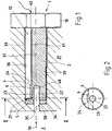
- the pressure sensor 1 consists of a base body 2, which is formed like a bolt 20.
- the main body 2 is, however, for example, prismatic or cylindrical, with all the geometries are considered as a prism, which have axially parallel, mutually parallel generatrices.
- the base body 2 is flattened over its entire length such that, in particular in the front region facing the pressure chamber 3, a flattening 24 results.
- the pressure sensor 1 is installed in a wall 31 which surrounds the pressure chamber 3.
- the pressure sensor 1 has an external thread and is equipped at the rear with a screw head 10 or a nut or the like. In the pressure chamber 3, there is the pressure to be measured 30.
- the pressure sensor 1 in a blind bore 32 (according to Fig. 1 ), or in a through hole 32 after Fig. 3 ,
- a seal 5 is arranged at the bottom 34 of the blind bore 32.
- the pressure sensor 1 or the main body 2 presses in the installed state on this seal. 5
- the membrane 4 is formed by a material weakening 23.
- This material weakening 23 of the main body 2 is realized on the one hand by the flattening 24 and on the other hand by a blind hole-like recess 22, which is arranged on the front side, the pressure chamber 3 facing the end of the main body 2 in this. It forms a web-like 40 membrane.
- the recess 32 can also be formed as an undercut, whereby, for example, a free-standing membrane plate is formed.
- the recess 22 is connected to the pressure chamber 3, such that in the recess 22, the same pressure 30 prevails as in the pressure chamber 3.
- an opening 35 is provided in the bottom 34 of the blind bore 32.
- the seal 5 here has an opening 50, the seal 5 is ring-shaped or disc-like.
- a measuring device 6 On the side facing away from the pressure 30 of the membrane 4, a measuring device 6 is arranged.
- the measuring device 6 serves to absorb the membrane deformation caused by the pressure 30 and to provide it as an evaluable signal.
- the measuring device 6 is connected to contact lines 61, such that the preferred electrical information, for example, a voltage drop or the like, depending on the type of measuring device 6, is passed to the back, where the contact line 61 opens into a terminal 62.
- the measuring device 6 as well as the contact line 61 is applied in a thin-film technology on the flattening 24 of the base body 2.
- a strain gauge 60 is preferably used as a measuring device 6. But there are also other concepts known and used.
- the membrane 4 acts directly on the seal 5 with its front, the pressure chamber 3 facing the end.
- the membrane 4 at the front end, facing the pressure chamber 3 is adjoined by a support rim 21, which mechanically stabilizes the membrane or supports it on the cylinder wall 36.
- a support rim 21 which mechanically stabilizes the membrane or supports it on the cylinder wall 36.
- an improved seal between the membrane and the pressure chamber 3 is produced by this support edge 21, because a considerably larger sealing surface on the support edge, if it is formed, for example, three-segmented, is provided for cooperation with the seal 5.
- the membrane 4 is obtained by a material weakening 23 in the pressure chamber 3 facing the end of the base body 2 by appropriate processing are provided on the base body 2, which lead to this material weakening.
- a recess 22 is provided, facing away from the pressure chamber, facing the measuring device 6, the flattening 24 is provided.
- the flattening 24 is arranged over the entire length of the base body 2 in order to facilitate the application of the contact lines 61.
- the recess 22 is oriented coaxially to the opening 35, whereby it does not depend on the exact radial arrangement of the bolt-like base body 2 in the bore 32.
- the recess 22 has the same diameter as the opening 35, but it can also be chosen different diameters, although this must be taken into account for a possible throttling effect, which may lead to an impairment of the pressure to be measured.
- the membrane 4 is disk-like 41. But here, too, the membrane 4 has been obtained from a material weakening of the main body 2.
- a Deutschenfräsung 25 which causes a disc or plate-like membrane 4, 41 is.
- a sleeve 7 is provided which receives the base body 2.
- the main body 2 in turn has an external thread, which cooperates with a corresponding internal thread of the sleeve 7.
- the arrangement is chosen so that the sleeve 7 supports the membrane 4 in the front, the pressure chamber 3 facing area.
- the disk-like membrane 41 rests on the sleeve edge 70.
- the sleeve in turn has an external thread through which the pressure sensor in the bore 32 can be screwed. By an appropriate fit, the arrangement is tight.
- the membrane is oriented at right angles to the bore axis 37. Of course, this arrangement can be used in the same way even when configured as a blind hole bore.
- the measuring device 6 is arranged, which is electrically connected by the contact line 61 to a terminal.
- the main body 2 is formed over its entire length as a flattened bolt 20 which carries at its end facing away from the pressure chamber 3, a fastening nut or a screw head, which is designed so that the contacting takes place through it.
- Fig. 4 an improved embodiment of the pressure sensor according to the invention is shown.
- the pressure sensor has a longitudinal extent.
- the pressure sensor 1 has in the right part of Fig. 4 a screw or nut head 10, through which the pressure sensor 1 by means of the thread 29, which is located on the left in front of the screw or nut head 10, in a corresponding thread of the opening of the pressure chamber (not shown here) can rotate.
- the pressure sensor 1 also has its greatest width, forwardly, in the direction of the membrane 4 (shown at the left end), the pressure sensor tapers regularly.
- the pressure sensor has high similarity with a spark plug or a glow plug in this embodiment.
- the membrane 4 which is followed only by the sealing seat 26 at the front end.
- the sealing seat 26 has, as described, the same tasks as the support edge 21 after Fig. 2 , the entire pressure sensor 1 is installed in a not shown (blind hole) bore 32 and the sealing seat 26 cooperates with a gradation, the bottom of the blind hole.
- the arrangement is chosen so that the front, end-side recess 22 is aligned with the opening 35 in the wall or communicates and so there is an immediate access to the volume of the pressure chamber 3.
- the underside of the membrane 4 is thus in contact with the pressure of the pressure chamber 3.
- the measuring device 6 which is designed as Dehnmeßstsammlung 60.
- four contact lines 61 are provided, can be tapped on the corresponding voltage changes due to the changed resistances of the strain gauges. This happens for example, according to a Wheatstone bridge principle. It is shown that the contact lines 61 initially run parallel and then spread apart, approximately in the same area in which the pressure sensor expands, and then run parallel again, in order then to open into corresponding contact surfaces 64.
- the contact surfaces 64 are arranged almost in the middle of the pressure sensor 1. It is favorable to arrange the contact surfaces 64 as far as possible in the rear region, which is generally cooler than the front region of the pressure sensor, since temperature-sensitive cable connections have to be applied to the contact surfaces 64.
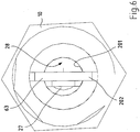
- Fig. 6 is the rear view of the pressure sensor after Fig. 4 shown.
- the end opening 28 is formed so that it is suitable to receive the board of an evaluation unit 63.
- 202 grooves 202 are incorporated, for example, in the side walls, which serve as a guide for the board of the evaluation unit 63.
- connection lines can now connect the contact surface 64 with the board of the evaluation unit 63.
- pressure sensor 1 is formed integrally at least in the region of the membrane, that is, the membrane 4 was by a corresponding taper created the wall thickness.
- the arrangement is chosen so that the conical sealing seat 26 is completely circumferential, the flattening 24 is thus discontinued in the foremost area, in the region of the sealing seat 26.
- This one-piece design has advantages in the tightness of the entire arrangement.
- Both the strain gauge 60 and the contact lines 61, including the contact surfaces 64, have preferably been applied in a common thin-film coating process.
- the entire pressure sensor is adjusted accordingly in a coating system and the flattening 24 is coated as desired. Since an electrically conductive base body is provided, for example, a corresponding insulating buffer layer is first applied, for example coated or sputtered, which then receives the strain gauge or the contact lines.
- silicon dioxide, sapphire (AL 2 O 3 ) and other known insulating materials which can be applied to a coating process are used as insulating substances.
- the traces are conveniently made of metal with the lowest possible resistivity such as gold or the like.
- Fig. 5 The structure shown is essentially the same as in Fig. 4 The structure shown is identical, which is why there is no repetition.
- the variant according to the invention Fig. 5 is different from the one in Fig. 4 in that the membrane 4 is not machined in one piece from the main body 1, but the base body 1 has a diaphragm opening 42 in the front region, through which when not built Membrane 4, as shown here, access from the top, the flattening 24 into the recess 22 is made.
- a corresponding membrane 4 is then installed in the membrane opening 42.
- the membrane 4 then has, for example, a relatively short contact line 61 and is then connected to the evaluation unit 63, for example by appropriate cable connections.
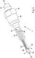
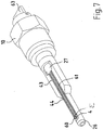
- Fig. 7 is another variant shown.
- the variant after Fig. 7 different from the one after Fig. 5 in that a significantly larger element is installed in the pressure sensor.
- a diaphragm opening 42 is provided.
- a diaphragm recess 43 which has just such a depth, as the element which is inserted into this there afterwards.
- These are the membrane holder 44.
- the membrane recess 43 is just created so that the membrane holder 44 is able to absorb rich.
- the membrane holder 44 holds the membrane 4 at its front end.
- the installation is of course such that the entire assembly is tight and the membrane is functional.
- the membrane holder 44 also carries the contact lines 61 at the same time.
- This variant is very favorable with regard to the thermal boundary conditions, since the membrane holder 44 extends over a long area, almost half of the total pressure sensor length, and the contact lines 61 thereafter are arranged and only at a relatively far inward, cooler place the bonding of the cable for connection to the evaluation unit 63 (through the opening 27) has to be done.
- a relatively long membrane holder is also optimal, if it serves completely, that is, in its entire length as a contact line 61, with regard to the utilization of the coating capacities.
- the contact lines 61 as well as the measuring device. 6
- Pressure sensors shown are usually just in the sensitive area of the measuring device 6 to protect.
- a sleeve 7 is conveniently pushed onto the front region of the pressure sensor 1.
- Such a sleeve 7 is for example in the variant after Fig. 8 shown.
- the variant shown here additionally has a glow plug 8, which dives out of the front end recess 22. Between the glow plug 8 and the wall of the recess 22 remains sufficient space to not hinder the pressure measurement by the membrane 4, which is hidden in this arrangement.
- the glow plug 8 has the task, for example, in a diesel engine, to provide for a preheating and thus to influence the starting behavior of the diesel engine low.
Landscapes
- Chemical & Material Sciences (AREA)
- Engineering & Computer Science (AREA)
- Combustion & Propulsion (AREA)
- Physics & Mathematics (AREA)
- General Physics & Mathematics (AREA)
- Measuring Fluid Pressure (AREA)
Claims (19)
- Capteur de pression, pouvant être placé dans une chambre à combustion cylindrique d'un moteur à combustion, consistant en une membrane séparant un dispositif de mesure, qui mesure la déformation de la membrane sous l'effet de la pression dans la chambre de pression et, étant formé à partir d'un corps de base, pouvant être introduit dans une ouverture dans une paroi délimitant la chambre de pression, avec la membrane orientée parallèlement ou sous un angle aigu par rapport à la normale à la surface de l'ouverture, et avec un corps de base possédant dans l'extrémité proche de la chambre de pression un trou borgne et dans l'extrémité proche de la chambre de pression une zone aplatie, caractérisé en ce que le corps de base comporte une ouverture pour la membrane formant un accès de la surface supérieure de la zone aplatie au trou borgne (22) et en ce que la membrane est introduit dans l'ouverture pour la membrane et fixé de façon étanche, par exemple pour soudage ou collage.
- Capteur de pression selon la revendication 1, caractérisé en ce que le capteur de pression (1) comporte des conducteurs de contact (61) pour interconnecter le dispositif de mesure (6) et une zone de contact (62) ou une unité d'analyse (63) et/ou en ce que le conducteur de contact (61) est prévu sur la face opposée de la chambre de pression (3) et/ou en ce que la membrane (4) fait partie d'un porte-membrane (44) et en ce que le porte-membrane (44) est placé dans un évidement (43) pour la membrane et/ou dans une ouverture (42) pour la membrane.
- Capteur de pression selon la revendication 2, caractérisé en ce que le porte-membrane (44) comporte des conducteurs de contact (61) et/ou en ce que le porte-membrane (44) s'étend le long de l'axe longitudinal du corps de base (2) avec une longueur supérieure à celle de l'extrémité avant du corps de base (2).
- Capteur de pression selon une des revendications précédentes, caractérisé en ce que la membrane (4) est créée par un affaiblissement du matériau (23) du corps de base (2) et/ou en ce que le corps de base (2) peut être lié de façon étanche à la paroi (31) et/ou en ce que le corps de base (2) peut être vissé dans un perçage (32) à filet (33) dans la paroi (31) et/ou en ce que le capteur de pression (1) est placé dans un perçage borgne (32) de la paroi (31) ayant au fond (34) une ouverture de passage (35) vers la chambre de pression.
- Capteur de pression selon la revendication 4, caractérisé en ce que le filet (33) est situé dans la partie arrière du corps de base (2) et/ou en ce que le corps de base (2) s'effile vers l'avant et/ou en ce que le corps de base (2) consiste en plusieurs parties élémentaires pouvant être liées de façon rigide entre elles et/ou en ce que le corps de base (2) comporte une tête de vis (10) et/ou en ce que le corps de base (2) possède une forme de boulon ou de tube.
- Capteur de pression selon une ou les deux revendications précédentes 4 et 5, caractérisé en ce que l'ouverture (35) et le perçage borgne (32) sont coaxiaux et/ou en ce qu'un joint d'étanchéité (5) est situé entre le capteur de pression (1) et le fond (34) du perçage (32) et/ou en ce que la membrane forme un angle aigu avec l'ouverture (35).
- Capteur de pression selon la revendication 6, caractérisé en ce que le capteur de pression (1) possède un bord d'appui (21) dans la zone de la membrane (4) qui interagit à l'état monté avec le joint d'étanchéité (5) et/ou en ce que l'extrémité avant du capteur de pression possède un siège d'étanchéité (26), en particulier un siège d'étanchéité conique (26) et en ce que le siège d'étanchéité (26) interagit avec la zone de la paroi (31) entourant l'ouverture (35).
- Capteur de pression selon la revendication 7, caractérisé en ce que le bord d'appui (21) possède une forme de disque et s'appuie contre la paroi cylindrique (36) du perçage (32) et/ou en ce que le bord d'appui (21) appuie la membrane (4) contre la paroi cylindrique (36) du perçage (32) et/ou en ce que le joint d'étanchéité (5) possède un perçage (50) et/ou en ce que l'ouverture (35), le perçage (50) et le perçage borgne (32) sont coaxiaux.
- Capteur de pression selon la revendication 1, caractérisé en ce que l'évidement (22) sert au moins partiellement par l'affaiblissement de matière (23) à la création de la membrane (4) et/ou en ce que l'aplatissement (24) sert au moins partiellement comme affaiblissement de matière (23) à la création de la membrane (4) et/ou en ce que l'aplatissement (24) comporte les conducteurs de contact (61).
- Capteur de pression selon la revendication 9, caractérisé en ce que la membrane (4) s'étend essentiellement parallèlement à l'axe (37) du perçage (32) et/ou en ce que la membrane (4) possède une forme d'une bande et/ou en ce que l'évidement (22) est coaxial par rapport à l'ouverture (35) et parallèle à la normale à la surface ou orienté à un angle aigu par rapport à la normale à la surface et/ou en ce que l'évidement (22) et l'ouverture (35) possèdent le même diamètre.
- Capteur de pression selon une des revendications 9 ou 10 ou selon plusieurs des revendications précédentes, caractérisé en ce que la membrane (4) est formée par un affaiblissement de matériau (23) du corps de base (2) de façon à ce que d'un côté est situé l'évidement (22) et de l'autre côté l'aplatissement (24) du corps de base (2) et/ou en ce que le corps de base (2) possède une ouverture d'extrémité (28) à son extrémité opposée à la chambre de pression recevant une unité d'analyse (63) et/ou une zone d'interconnexion (62).
- Capteur de pression selon la revendication 11, caractérisé en ce que l'unité d'analyse (63) est située sur une platine et en ce que des gorges de guidage (202) prévues pour recevoir la platine existe au niveau de l'ouverture d'extrémité (28) et/ou en ce que les conducteurs de contact (61) comportent au moins à leur face opposée à la membrane (4) des surfaces de contact (64) permettant l'adhésion de conducteurs d'interconnexion.
- Capteur de pression selon une des revendications 11 ou 12, caractérisé en ce que l'aplatissement (24) possède à son extrémité opposée à la membrane (4) un perçage (27) vers l'ouverture d'extrémité (28) et/ou en ce que le corps de base (2) comporte une douille (7) et, le cas échéant, la douille (7) pouvant être fixée, voire vissée dans un perçage (32) dans la paroi (31).
- Capteur de pression selon une des revendications précédentes, caractérisé en ce que la membrane (4) possède une forme de disque (41) et/ou en ce que la membrane (4) est générée par un fraisage arrière (25) du corps de base (2) et/ou en ce que la membrane (4) s'appuie au moins sur une partie du bord de douille (70).
- Capteur de pression selon une des revendications précédentes, caractérisé par un dispositif de mesure (6) à base résistive, capacitive ou inductive et/ou par un dispositif de mesure (6) est réalisée par une jauge de contrainte (60) située sur la membrane (4) et/ou caractérisé en ce que la dispositif de mesure (6) comportant de plus un capteur de température.
- Capteur de pression selon la revendication 15, caractérisé en ce que le dispositif de mesure (6) est réalisé selon la technologie en couches minces déposées sur la membrane et/ou en ce que les conducteurs de contact (61) est formé par des couches minces ou fabriqué selon la technologie en couches minces et/ou en ce que le dispositif de mesure (6) et les conducteurs de contact (61) sont déposés en une étape de fabrication commune sur le corps de base ou sur le porte-membrane et/ou en ce qu'au niveau de l'extrémité du corps de base (2) opposé à la chambre de pression (3), le conducteur de contact (61) est terminé par un connecteur (62).
- Capteur de pression selon l'une des revendications précédentes 9 à 16, caractérisé en ce que le corps de base (2) possède au moins partiellement une forme de prisme et, au moins dans la zone faisant face à la chambre de pression (3), un aplatissement (24) et en ce que le corps de base (2) possède un évidement (22) au niveau de sa face frontale située en face de la chambre de pression de sorte que la membrane (4) est située entre l'aplatissement (24) et l'évidement (22) et/ou en ce que le corps de base (2) ou la membrane (4) est en métal ou en un matériau fritté, tel que de la céramique ou des matériaux similaires.
- Capteur de pression selon une des revendications précédentes 9 à 17, caractérisé en ce que l'évidement (22) reçoit une tige d'allumage (8) et/ou en ce que la tige d'allumage (8) est située à une distance donnée de la paroi intérieure de l'évidement (22) et de la membrane (4) et/ou en ce que la tige d'allumage (8) ne ferme pas l'évidement (22) et dépasse le bord de l'évidement (22) et/ou en ce que l'extrémité de la tige d'allumage (8) dépassant le bord de l'évidement (22) vers l'intérieur de la chambre de pression (3) s'échauffe lors de l'application d'un courant électrique sur cette tige d'allumage.
- Dispositif de détection de la pression destiné aux moteurs à combustion ayant une paroi (31) délimitant la chambre de pression (3) et comportant un perçage ou un perçage non débouchant (32) afin de recevoir un capteur de pression selon une des revendications précédentes.
Applications Claiming Priority (2)
| Application Number | Priority Date | Filing Date | Title |
|---|---|---|---|
| DE10360941A DE10360941A1 (de) | 2003-12-23 | 2003-12-23 | Rohrförmiger Drucksensor |
| PCT/EP2004/013970 WO2005064298A2 (fr) | 2003-12-23 | 2004-12-08 | Capteur de pression |
Publications (2)
| Publication Number | Publication Date |
|---|---|
| EP1704397A2 EP1704397A2 (fr) | 2006-09-27 |
| EP1704397B1 true EP1704397B1 (fr) | 2017-02-08 |
Family
ID=34706526
Family Applications (1)
| Application Number | Title | Priority Date | Filing Date |
|---|---|---|---|
| EP04820819.3A Expired - Lifetime EP1704397B1 (fr) | 2003-12-23 | 2004-12-08 | Capteur de pression |
Country Status (4)
| Country | Link |
|---|---|
| US (1) | US7530275B2 (fr) |
| EP (1) | EP1704397B1 (fr) |
| DE (1) | DE10360941A1 (fr) |
| WO (1) | WO2005064298A2 (fr) |
Families Citing this family (16)
| Publication number | Priority date | Publication date | Assignee | Title |
|---|---|---|---|---|
| DE102004063750A1 (de) * | 2004-12-29 | 2006-07-13 | Robert Bosch Gmbh | Glühstiftkerze mit integriertem Brennraumdrucksensor |
| DE102005050502B3 (de) * | 2005-10-21 | 2007-04-05 | Giese, Erhard, Dr. | Glühkerze für einen Dieselmotor |
| DE102006041124B4 (de) * | 2006-09-01 | 2008-06-26 | Beru Ag | Glühkerze mit eingebautem Drucksensor |
| DE102007009994A1 (de) | 2007-03-01 | 2008-09-04 | Robert Bosch Gmbh | Induktiver Sensor |
| US8028584B2 (en) * | 2007-08-20 | 2011-10-04 | Denso Corporation | Pressure sensor and method for manufacturing the same |
| DE102008017151B3 (de) * | 2008-04-03 | 2009-08-27 | Continental Automotive Gmbh | Kraftstoff-Einspritzsystem für eine Brennkraftmaschine |
| US9354132B2 (en) | 2009-02-12 | 2016-05-31 | Continental Automotive Systems, Inc. | Jointless pressure sensor port |
| US8365605B2 (en) * | 2009-02-12 | 2013-02-05 | Continental Automotive Systems, Inc. | Jointless pressure sensor port |
| DE102009050911B4 (de) * | 2009-10-26 | 2014-06-12 | Borgwarner Beru Systems Gmbh | Zylinderdrucksensor |
| US20120227507A1 (en) * | 2011-01-10 | 2012-09-13 | Hani Sabri Mitri | Instrumented coupler load cell for rock anchors |
| DE102014010116B4 (de) | 2013-04-29 | 2018-11-15 | Elmos Semiconductor Aktiengesellschaft | MEMS Sensor für schwierige Umgebungen und Medien |
| WO2015066310A1 (fr) * | 2013-10-30 | 2015-05-07 | Lime Instruments Llc | Ensemble capteur pour mesure de pression dynamique dans des pompes alternatives |
| DE102015206468A1 (de) * | 2015-04-10 | 2016-10-13 | Robert Bosch Gmbh | Vorrichtung zum Bestimmen eines Drucks und Verfahren zum Herstellen derselben |
| DE102015207307A1 (de) * | 2015-04-22 | 2016-10-27 | Robert Bosch Gmbh | Kraftstoffinjektor |
| CN108814689B (zh) * | 2018-06-12 | 2024-06-04 | 南昌大学 | 一种差动式膜片光纤压力传感系统 |
| CN114812898B (zh) * | 2022-03-10 | 2023-10-27 | 森霸传感科技股份有限公司 | 一种带有薄膜传感器的构件及制备方法 |
Citations (1)
| Publication number | Priority date | Publication date | Assignee | Title |
|---|---|---|---|---|
| US3645136A (en) * | 1970-04-15 | 1972-02-29 | Charles W Calhoun | Fluid pressure measuring device |
Family Cites Families (11)
| Publication number | Priority date | Publication date | Assignee | Title |
|---|---|---|---|---|
| DE3313261A1 (de) * | 1983-04-13 | 1984-10-25 | Ermeto Armaturen Gmbh, 4800 Bielefeld | Sensor |
| DE3528768A1 (de) * | 1984-10-25 | 1986-05-07 | Robert Bosch Gmbh, 7000 Stuttgart | Drucksensor |
| DE3616308C2 (de) * | 1986-05-14 | 1995-09-21 | Bosch Gmbh Robert | Sensor |
| DE3912177A1 (de) * | 1989-04-13 | 1990-10-18 | Siemens Ag | Drucksensor fuer den verbrennungsraum von kolben-verbrennungsmotoren |
| US5195365A (en) * | 1990-08-24 | 1993-03-23 | Toyota Jidosha Kabushiki Kaisha | Device for detecting combustion pressure of an internal combustion engine |
| JPH0719981A (ja) * | 1993-06-01 | 1995-01-20 | Nippondenso Co Ltd | 高温用圧力センサ |
| US5714680A (en) * | 1993-11-04 | 1998-02-03 | The Texas A&M University System | Method and apparatus for measuring pressure with fiber optics |
| US5712424A (en) * | 1996-03-25 | 1998-01-27 | The United States Of America As Represented By The Secretary Of The Navy | Method and apparatus for measuring diesel engine cylinder pressure |
| US6622549B1 (en) * | 1997-02-06 | 2003-09-23 | Marek T. Wlodarczyk | Fuel injectors with integral fiber optic pressure sensors and associated compensation and status monitoring devices |
| WO2004081510A1 (fr) * | 2003-03-10 | 2004-09-23 | Danfoss A/S | Capteur de pression sur silicium a egalisation de pression reduite entre une pression mesuree et une chambre de pression |
| DE102005022087B4 (de) * | 2004-05-17 | 2013-10-31 | Denso Corporation | Druckerfassungsvorrichtung |
-
2003
- 2003-12-23 DE DE10360941A patent/DE10360941A1/de not_active Withdrawn
-
2004
- 2004-12-08 WO PCT/EP2004/013970 patent/WO2005064298A2/fr not_active Ceased
- 2004-12-08 EP EP04820819.3A patent/EP1704397B1/fr not_active Expired - Lifetime
-
2006
- 2006-06-23 US US11/473,054 patent/US7530275B2/en not_active Expired - Lifetime
Patent Citations (1)
| Publication number | Priority date | Publication date | Assignee | Title |
|---|---|---|---|---|
| US3645136A (en) * | 1970-04-15 | 1972-02-29 | Charles W Calhoun | Fluid pressure measuring device |
Also Published As
| Publication number | Publication date |
|---|---|
| US20070006641A1 (en) | 2007-01-11 |
| EP1704397A2 (fr) | 2006-09-27 |
| US7530275B2 (en) | 2009-05-12 |
| DE10360941A1 (de) | 2005-07-28 |
| WO2005064298A2 (fr) | 2005-07-14 |
| WO2005064298A3 (fr) | 2006-04-20 |
Similar Documents
| Publication | Publication Date | Title |
|---|---|---|
| EP1704397B1 (fr) | Capteur de pression | |
| EP1847777B1 (fr) | Bougie de préchauffage dotée d'un capteur de pression intégré | |
| EP0594808B1 (fr) | Dispositif permettant de mesurer la pression et la pression differentielle avec une boite filetee en trois parties et une corniere annulaire | |
| DE10212908B4 (de) | Temperatursensor und Herstellungsverfahren dafür | |
| DE4010609C2 (de) | Zündkerze mit Einrichtungen zur Temperatur- und Druckerfassung | |
| DE102014209404B4 (de) | Gassensor | |
| EP1881308A1 (fr) | Sonde de température pour un thermomètre à résistance, en particulier destiné à l'utilisation dans un système d'échappement de moteurs à combustion | |
| DE10127932A1 (de) | Ventil zum Steuern von Fluiden sowie Verfahren zur Bestimmung von Drücken | |
| EP2047223B1 (fr) | Dispositif de détection de pression | |
| EP1856497A1 (fr) | Composant pour capteurs de force ou de pression, dont les elements sont maintenus les uns avec les autres par un film electro-isolant | |
| EP3176555B1 (fr) | Capteur de pression piezoelectrique et son procédé de fabrication | |
| EP0938651A1 (fr) | Capteur de pression et de temperature | |
| WO2010060616A2 (fr) | Bougie de préchauffage et son procédé de fabrication | |
| DE69614429T2 (de) | Widerstandsschweiss-Sensor | |
| EP2002254B9 (fr) | Procede de fabrication d'une sonde de mesure pour applications a haute temperature | |
| EP0056383B1 (fr) | Detecteur | |
| EP0140066A1 (fr) | Dispositif pour la détection de forces, tensions resp. des accélérations de machines, appareils ou similaires | |
| DE102013211479B4 (de) | Vorrichtung zur Erfassung eines Drucks und einer Temperatur eines Mediums | |
| DE69405788T2 (de) | Zündkerze mit eingebautem Drucksensor | |
| EP1255099B1 (fr) | Capteur de pression pour capter la pression dans la chambre de combustion d'un moteur et son procédé de fabrication | |
| EP1967834B1 (fr) | Bougie d'allumage avec un capteur de mesure de pression | |
| CH666127A5 (de) | Messwertaufnehmer zur messung heisser medien, sowie verfahren zu seiner montage. | |
| DE10058013A1 (de) | Gasmeßfühler | |
| EP2853874A2 (fr) | Dispositif destiné à déterminer au moins une propriété d'un milieu liquide | |
| EP0179278A2 (fr) | Capteur de pression |
Legal Events
| Date | Code | Title | Description |
|---|---|---|---|
| PUAI | Public reference made under article 153(3) epc to a published international application that has entered the european phase |
Free format text: ORIGINAL CODE: 0009012 |
|
| 17P | Request for examination filed |
Effective date: 20060713 |
|
| AK | Designated contracting states |
Kind code of ref document: A2 Designated state(s): AT BE BG CH CY CZ DE DK EE ES FI FR GB GR HU IE IS IT LI LT LU MC NL PL PT RO SE SI SK TR |
|
| AX | Request for extension of the european patent |
Extension state: AL BA HR LV MK YU |
|
| RAP1 | Party data changed (applicant data changed or rights of an application transferred) |
Owner name: KMW KAUFBEURER MIKROSYSTEME WIEDMANN GMBH |
|
| DAX | Request for extension of the european patent (deleted) | ||
| 17Q | First examination report despatched |
Effective date: 20090416 |
|
| REG | Reference to a national code |
Ref country code: DE Ref legal event code: R079 Ref document number: 502004015457 Country of ref document: DE Free format text: PREVIOUS MAIN CLASS: G01L0023180000 Ipc: G01L0023120000 |
|
| RIC1 | Information provided on ipc code assigned before grant |
Ipc: G01L 23/12 20060101AFI20160108BHEP Ipc: G01L 23/18 20060101ALI20160108BHEP |
|
| GRAP | Despatch of communication of intention to grant a patent |
Free format text: ORIGINAL CODE: EPIDOSNIGR1 |
|
| INTG | Intention to grant announced |
Effective date: 20160310 |
|
| GRAJ | Information related to disapproval of communication of intention to grant by the applicant or resumption of examination proceedings by the epo deleted |
Free format text: ORIGINAL CODE: EPIDOSDIGR1 |
|
| INTC | Intention to grant announced (deleted) | ||
| GRAP | Despatch of communication of intention to grant a patent |
Free format text: ORIGINAL CODE: EPIDOSNIGR1 |
|
| INTG | Intention to grant announced |
Effective date: 20160908 |
|
| GRAS | Grant fee paid |
Free format text: ORIGINAL CODE: EPIDOSNIGR3 |
|
| GRAA | (expected) grant |
Free format text: ORIGINAL CODE: 0009210 |
|
| AK | Designated contracting states |
Kind code of ref document: B1 Designated state(s): AT BE BG CH CY CZ DE DK EE ES FI FR GB GR HU IE IS IT LI LT LU MC NL PL PT RO SE SI SK TR |
|
| REG | Reference to a national code |
Ref country code: GB Ref legal event code: FG4D Free format text: NOT ENGLISH |
|
| REG | Reference to a national code |
Ref country code: CH Ref legal event code: EP Ref country code: AT Ref legal event code: REF Ref document number: 867084 Country of ref document: AT Kind code of ref document: T Effective date: 20170215 |
|
| REG | Reference to a national code |
Ref country code: IE Ref legal event code: FG4D Free format text: LANGUAGE OF EP DOCUMENT: GERMAN |
|
| REG | Reference to a national code |
Ref country code: DE Ref legal event code: R096 Ref document number: 502004015457 Country of ref document: DE |
|
| REG | Reference to a national code |
Ref country code: LT Ref legal event code: MG4D |
|
| REG | Reference to a national code |
Ref country code: NL Ref legal event code: MP Effective date: 20170208 |
|
| PG25 | Lapsed in a contracting state [announced via postgrant information from national office to epo] |
Ref country code: GR Free format text: LAPSE BECAUSE OF FAILURE TO SUBMIT A TRANSLATION OF THE DESCRIPTION OR TO PAY THE FEE WITHIN THE PRESCRIBED TIME-LIMIT Effective date: 20170509 Ref country code: FI Free format text: LAPSE BECAUSE OF FAILURE TO SUBMIT A TRANSLATION OF THE DESCRIPTION OR TO PAY THE FEE WITHIN THE PRESCRIBED TIME-LIMIT Effective date: 20170208 Ref country code: LT Free format text: LAPSE BECAUSE OF FAILURE TO SUBMIT A TRANSLATION OF THE DESCRIPTION OR TO PAY THE FEE WITHIN THE PRESCRIBED TIME-LIMIT Effective date: 20170208 |
|
| PG25 | Lapsed in a contracting state [announced via postgrant information from national office to epo] |
Ref country code: SE Free format text: LAPSE BECAUSE OF FAILURE TO SUBMIT A TRANSLATION OF THE DESCRIPTION OR TO PAY THE FEE WITHIN THE PRESCRIBED TIME-LIMIT Effective date: 20170208 Ref country code: BG Free format text: LAPSE BECAUSE OF FAILURE TO SUBMIT A TRANSLATION OF THE DESCRIPTION OR TO PAY THE FEE WITHIN THE PRESCRIBED TIME-LIMIT Effective date: 20170508 Ref country code: PT Free format text: LAPSE BECAUSE OF FAILURE TO SUBMIT A TRANSLATION OF THE DESCRIPTION OR TO PAY THE FEE WITHIN THE PRESCRIBED TIME-LIMIT Effective date: 20170608 Ref country code: ES Free format text: LAPSE BECAUSE OF FAILURE TO SUBMIT A TRANSLATION OF THE DESCRIPTION OR TO PAY THE FEE WITHIN THE PRESCRIBED TIME-LIMIT Effective date: 20170208 Ref country code: NL Free format text: LAPSE BECAUSE OF FAILURE TO SUBMIT A TRANSLATION OF THE DESCRIPTION OR TO PAY THE FEE WITHIN THE PRESCRIBED TIME-LIMIT Effective date: 20170208 |
|
| PG25 | Lapsed in a contracting state [announced via postgrant information from national office to epo] |
Ref country code: EE Free format text: LAPSE BECAUSE OF FAILURE TO SUBMIT A TRANSLATION OF THE DESCRIPTION OR TO PAY THE FEE WITHIN THE PRESCRIBED TIME-LIMIT Effective date: 20170208 Ref country code: CZ Free format text: LAPSE BECAUSE OF FAILURE TO SUBMIT A TRANSLATION OF THE DESCRIPTION OR TO PAY THE FEE WITHIN THE PRESCRIBED TIME-LIMIT Effective date: 20170208 Ref country code: RO Free format text: LAPSE BECAUSE OF FAILURE TO SUBMIT A TRANSLATION OF THE DESCRIPTION OR TO PAY THE FEE WITHIN THE PRESCRIBED TIME-LIMIT Effective date: 20170208 Ref country code: IT Free format text: LAPSE BECAUSE OF FAILURE TO SUBMIT A TRANSLATION OF THE DESCRIPTION OR TO PAY THE FEE WITHIN THE PRESCRIBED TIME-LIMIT Effective date: 20170208 Ref country code: SK Free format text: LAPSE BECAUSE OF FAILURE TO SUBMIT A TRANSLATION OF THE DESCRIPTION OR TO PAY THE FEE WITHIN THE PRESCRIBED TIME-LIMIT Effective date: 20170208 |
|
| REG | Reference to a national code |
Ref country code: DE Ref legal event code: R097 Ref document number: 502004015457 Country of ref document: DE |
|
| PG25 | Lapsed in a contracting state [announced via postgrant information from national office to epo] |
Ref country code: DK Free format text: LAPSE BECAUSE OF FAILURE TO SUBMIT A TRANSLATION OF THE DESCRIPTION OR TO PAY THE FEE WITHIN THE PRESCRIBED TIME-LIMIT Effective date: 20170208 Ref country code: PL Free format text: LAPSE BECAUSE OF FAILURE TO SUBMIT A TRANSLATION OF THE DESCRIPTION OR TO PAY THE FEE WITHIN THE PRESCRIBED TIME-LIMIT Effective date: 20170208 |
|
| PLBE | No opposition filed within time limit |
Free format text: ORIGINAL CODE: 0009261 |
|
| STAA | Information on the status of an ep patent application or granted ep patent |
Free format text: STATUS: NO OPPOSITION FILED WITHIN TIME LIMIT |
|
| 26N | No opposition filed |
Effective date: 20171109 |
|
| PG25 | Lapsed in a contracting state [announced via postgrant information from national office to epo] |
Ref country code: SI Free format text: LAPSE BECAUSE OF FAILURE TO SUBMIT A TRANSLATION OF THE DESCRIPTION OR TO PAY THE FEE WITHIN THE PRESCRIBED TIME-LIMIT Effective date: 20170208 |
|
| REG | Reference to a national code |
Ref country code: CH Ref legal event code: PL |
|
| GBPC | Gb: european patent ceased through non-payment of renewal fee |
Effective date: 20171208 |
|
| REG | Reference to a national code |
Ref country code: IE Ref legal event code: MM4A |
|
| PG25 | Lapsed in a contracting state [announced via postgrant information from national office to epo] |
Ref country code: LU Free format text: LAPSE BECAUSE OF NON-PAYMENT OF DUE FEES Effective date: 20171208 |
|
| REG | Reference to a national code |
Ref country code: FR Ref legal event code: ST Effective date: 20180831 |
|
| REG | Reference to a national code |
Ref country code: BE Ref legal event code: MM Effective date: 20171231 |
|
| PG25 | Lapsed in a contracting state [announced via postgrant information from national office to epo] |
Ref country code: FR Free format text: LAPSE BECAUSE OF NON-PAYMENT OF DUE FEES Effective date: 20180102 Ref country code: IE Free format text: LAPSE BECAUSE OF NON-PAYMENT OF DUE FEES Effective date: 20171208 |
|
| PG25 | Lapsed in a contracting state [announced via postgrant information from national office to epo] |
Ref country code: GB Free format text: LAPSE BECAUSE OF NON-PAYMENT OF DUE FEES Effective date: 20171208 Ref country code: LI Free format text: LAPSE BECAUSE OF NON-PAYMENT OF DUE FEES Effective date: 20171231 Ref country code: CH Free format text: LAPSE BECAUSE OF NON-PAYMENT OF DUE FEES Effective date: 20171231 Ref country code: BE Free format text: LAPSE BECAUSE OF NON-PAYMENT OF DUE FEES Effective date: 20171231 |
|
| REG | Reference to a national code |
Ref country code: AT Ref legal event code: MM01 Ref document number: 867084 Country of ref document: AT Kind code of ref document: T Effective date: 20171208 |
|
| PG25 | Lapsed in a contracting state [announced via postgrant information from national office to epo] |
Ref country code: AT Free format text: LAPSE BECAUSE OF NON-PAYMENT OF DUE FEES Effective date: 20171208 |
|
| PG25 | Lapsed in a contracting state [announced via postgrant information from national office to epo] |
Ref country code: MC Free format text: LAPSE BECAUSE OF FAILURE TO SUBMIT A TRANSLATION OF THE DESCRIPTION OR TO PAY THE FEE WITHIN THE PRESCRIBED TIME-LIMIT Effective date: 20170208 Ref country code: HU Free format text: LAPSE BECAUSE OF FAILURE TO SUBMIT A TRANSLATION OF THE DESCRIPTION OR TO PAY THE FEE WITHIN THE PRESCRIBED TIME-LIMIT; INVALID AB INITIO Effective date: 20041208 |
|
| REG | Reference to a national code |
Ref country code: DE Ref legal event code: R082 Ref document number: 502004015457 Country of ref document: DE Representative=s name: PATENTANWAELTE OLBRICHT, BUCHHOLD, KEULERTZ PA, DE |
|
| PG25 | Lapsed in a contracting state [announced via postgrant information from national office to epo] |
Ref country code: CY Free format text: LAPSE BECAUSE OF NON-PAYMENT OF DUE FEES Effective date: 20170208 |
|
| PG25 | Lapsed in a contracting state [announced via postgrant information from national office to epo] |
Ref country code: TR Free format text: LAPSE BECAUSE OF FAILURE TO SUBMIT A TRANSLATION OF THE DESCRIPTION OR TO PAY THE FEE WITHIN THE PRESCRIBED TIME-LIMIT Effective date: 20170208 |
|
| PGFP | Annual fee paid to national office [announced via postgrant information from national office to epo] |
Ref country code: DE Payment date: 20200114 Year of fee payment: 16 |
|
| PG25 | Lapsed in a contracting state [announced via postgrant information from national office to epo] |
Ref country code: IS Free format text: LAPSE BECAUSE OF FAILURE TO SUBMIT A TRANSLATION OF THE DESCRIPTION OR TO PAY THE FEE WITHIN THE PRESCRIBED TIME-LIMIT Effective date: 20170608 |
|
| REG | Reference to a national code |
Ref country code: DE Ref legal event code: R119 Ref document number: 502004015457 Country of ref document: DE |
|
| PG25 | Lapsed in a contracting state [announced via postgrant information from national office to epo] |
Ref country code: DE Free format text: LAPSE BECAUSE OF NON-PAYMENT OF DUE FEES Effective date: 20210701 |