EP2853874A2 - Dispositif destiné à déterminer au moins une propriété d'un milieu liquide - Google Patents
Dispositif destiné à déterminer au moins une propriété d'un milieu liquide Download PDFInfo
- Publication number
- EP2853874A2 EP2853874A2 EP14179956.9A EP14179956A EP2853874A2 EP 2853874 A2 EP2853874 A2 EP 2853874A2 EP 14179956 A EP14179956 A EP 14179956A EP 2853874 A2 EP2853874 A2 EP 2853874A2
- Authority
- EP
- European Patent Office
- Prior art keywords
- pressure
- throttle
- discharge nozzle
- fluid medium
- pressure sensor
- Prior art date
- Legal status (The legal status is an assumption and is not a legal conclusion. Google has not performed a legal analysis and makes no representation as to the accuracy of the status listed.)
- Ceased
Links
Images


Classifications
-
- G—PHYSICS
- G01—MEASURING; TESTING
- G01L—MEASURING FORCE, STRESS, TORQUE, WORK, MECHANICAL POWER, MECHANICAL EFFICIENCY, OR FLUID PRESSURE
- G01L19/00—Details of, or accessories for, apparatus for measuring steady or quasi-steady pressure of a fluent medium insofar as such details or accessories are not special to particular types of pressure gauges
- G01L19/06—Means for preventing overload or deleterious influence of the measured medium on the measuring device or vice versa
- G01L19/0609—Pressure pulsation damping arrangements
-
- G—PHYSICS
- G01—MEASURING; TESTING
- G01L—MEASURING FORCE, STRESS, TORQUE, WORK, MECHANICAL POWER, MECHANICAL EFFICIENCY, OR FLUID PRESSURE
- G01L19/00—Details of, or accessories for, apparatus for measuring steady or quasi-steady pressure of a fluent medium insofar as such details or accessories are not special to particular types of pressure gauges
- G01L19/0092—Pressure sensor associated with other sensors, e.g. for measuring acceleration or temperature
Definitions
- the invention relates to a device for detecting at least one property of a fluid medium having the features of the independent claim.
- a fluid medium may be, for example, a gas and / or a liquid.
- the at least one property which can be detected qualitatively or quantitatively, can be any physical and / or chemical property of the fluid medium or a flow of the fluid medium.
- sensors are known, which are set up to detect at least one temperature of the fluid medium.
- combination sensors which in addition to a temperature can still detect a pressure of the fluid medium (pT sensors), also called pressure sensors with integrated temperature sensor.
- PT sensors pressure sensors with integrated temperature sensor.
- Such sensors are for example in Konrad Reif: Sensors in the motor vehicle, 2nd edition 2012, pages 134-136 , described.
- Such pT sensors are used in particular in hydraulic systems.
- An important field of application for pT sensors is the automotive technology, in particular in a fuel-carrying system and / or an oil circuit of a motor vehicle.
- alternative fuels such as compressed natural gas (CNG), liquefied petroleum gas (LPG), ethanol, or similar alternative fuels necessitates the use of adapted sensors to determine physical variables such as pressure and temperature in the intake manifold or in the fuel system ,
- so-called medium-pressure sensors make it possible to measure pressure and temperature in a motor system operated with ethanol-containing fuel.
- Such pT sensors usually have a housing which has a discharge nozzle with a Has external thread and which can be screwed into the fuel or oil system.
- a pressure sensor element On the discharge nozzle, a pressure sensor element is applied, which is connected via a bore with the fuel system. Furthermore protrudes from the discharge nozzle a temperature measuring finger in the fluid medium, in which a temperature sensor in the form of an NTC resistor (resistor with negative temperature coefficient) is added.
- NTC resistor resistor with negative temperature coefficient
- changes in the flow velocity of the fluid medium can occur, for example, by actuation of a valve.
- this can lead to rapid pressure changes, so-called pressure surges, and cavitation pulses, which can damage the measuring elements of the sensors.
- throttle elements For pressure sensors without temperature sensor is known from the prior art, additional components, so-called throttle elements, also called throttle, to install a reduction in cross section of the bore in pressure sensors to prevent such damage.
- throttle elements can dampen a dynamics and amplitude of such undesirable pressure changes.
- a pressure sensor is used for example in DE 10 2006 051 192 B4 described.
- the pressure sensor has a housing which has a pressure introduction opening for introducing a medium to be measured.
- the pressure introduction port has at least one throttle-like location in the form of a reduced diameter section where a cross-sectional area of the pressure introduction port is reduced.
- a relative pressure sensor with two chambers and two separation membranes for a process pressure and an ambient pressure is described.
- the chambers are separated by a pressure sensitive element and filled with a transfer medium.
- a hydraulic throttle is provided, which is arranged on the atmosphere side between the second separation membrane and the pressure-sensitive element.
- a limiting element for a pressure sensor which has a housing with a liquid inlet channel and a pressure element arranged in a chamber. Inside the chamber between the Pressure element and the liquid inlet channel is a limiting element arranged to protect the pressure element from flow-related damage.
- throttle elements are usually produced in a deep-drawing process.
- an additional manufacturing step for example, welding or caulking necessary to ensure loss of security of the throttle elements.
- a loss of the throttle element during operation of the fuel-carrying system and / or in the oil circuit of the motor vehicle may result in damage to the motor vehicle, in particular engine damage.
- additional components for damping pressure changes are not known for pressure sensors with integrated temperature sensor.
- a device for detecting at least one property of a fluid medium in a measuring space, which further develops the prior art described above in an advantageous manner.
- the fluid medium can basically be a gas and / or a liquid.
- the at least one property may be any physical and / or chemical property of the fluid medium, in particular the at least one property may be the pressure of the fluid medium.
- a measuring space is to be understood as a space encompassing the fluid medium.
- the invention can be used in particular in the field of automotive engineering, so that the measuring space can be, for example, an intake manifold, a fuel system or an oil system, for example for engine and / or transmission attachment.
- a device which comprises at least one pressure sensor element for detecting a pressure of the fluid medium.
- a pressure sensor element can be understood to be a component which is set up to convert a physical measured variable, such as the pressure of a medium, into an electrical signal, preferably an electrical voltage and / or an electrical current.
- the pressure sensor element generates a corresponding pressure-dependent output signal, for example in the form of a voltage and / or a current, as a function of a pressure exerted on it.
- the device comprises a pressure port with at least one pressure bore for supplying the fluid medium to the pressure sensor element.
- a pressure connection may be understood to mean a component which is set up to guide the fluid medium to the pressure sensor element.
- the discharge nozzle may for example be rotationally symmetrical, for example in the form of a hollow cylinder, designed. However, another embodiment is also conceivable.
- the discharge nozzle can for example be made of steel, light metal, aluminum or brass.
- the pressure bore can basically be a bore or opening with an arbitrary cross-sectional area, for example a cylindrical bore with a round or polygonal cross-section.
- the pressure sensor element is held by means of at least one support element and connected to the discharge nozzle.
- a carrier element can be understood as meaning a component which is set up to hold further components, in particular the pressure sensor element, in the device.
- the term "held” may include that the carrier element may be formed separately from the pressure sensor element and the pressure sensor element may rest on the carrier element and be held in the device, and / or that the pressure sensor element may be fully or partially integrated in the carrier element.
- the carrier element may be configured as a separate component, independently of the pressure sensor element.
- the carrier element may also completely or partially comprise the pressure sensor element, for example as an integral component.
- the pressure sensor element may comprise a membrane, which is applied to the carrier element, wherein the carrier element may be configured for example in the form of a hollow cylinder or ring whose opening is completely or partially covered or covered by the membrane.
- the configuration that the pressure sensor element is held by means of at least one support member and connected to the discharge nozzle so be realized in that the pressure sensor element and the support element are designed as separate elements, wherein the support member spatially positions the pressure sensor element and / or fixed, or in that the pressure sensor element and the carrier element are at least partially formed in one piece and / or connected to one another.
- the carrier element may have a fundamentally arbitrarily shaped support on which the pressure sensor element rests.
- the support element can by a positive and / or cohesive connection to be connected to the discharge nozzle.
- the carrier element may consist wholly or partly of Kovar and / or steel.
- At least one throttle element is embedded in a form-fitting manner.
- a throttle element can generally be understood an element having at least one throttle channel, wherein the throttle channel has a smaller diameter or equivalent diameter than a pressure channel before and after the throttle element.
- a throttle channel can generally be understood to mean a bore or opening in the throttle element, for example a cylindrical bore of basically any cross-section, through which the fluid medium can pass into the pressure channel downstream of the throttle element.
- a channel between the measuring chamber and the pressure sensor element can be understood.
- the pressure channel may include the pressure bore of the pressure nozzle, the throttle channel and a carrier channel.
- the pressure bore of the pressure nozzle can, in an inflow direction of the fluid medium into the device, be arranged in front of the throttle element.
- the carrier channel can be understood as a channel section between the throttle element and the pressure sensor element.
- the throttle element can be understood as an element with a higher flow resistance than a flow resistance of adjacent sections of the pressure channel.
- the device can have at least one temperature sensor for detecting a temperature of the fluid medium.
- the temperature sensor may be, for example, a thermistor with a negative temperature coefficient (NTC) and / or another temperature-dependent resistance.
- NTC negative temperature coefficient
- the temperature sensor can be accommodated at least partially in at least one temperature sensor channel in the discharge nozzle.
- the temperature sensing channel may be a bore or opening in the discharge nozzle, for example a cylindrical or curved elongated cavity, which extends, for example obliquely, in particular at an angle, to an installation axis of the device.
- the angle between the temperature sensor channel and the installation axis may for example be between 0 ° and 45 °, in particular between 5 ° and 20 °.
- the installation axis can be defined here by the installation direction of the device in the measuring space.
- the temperature sensor can be accommodated at least partially in at least one measuring finger projecting into the fluid medium.
- the measuring finger can be arranged obliquely to the installation axis of the device.
- the temperature sensor can have at least one temperature sensor element.
- a measuring finger can generally be understood to mean a housing element, in particular a housing element which is closed at the end and has an interior space in which at least one measuring element can be received, and which projects into the measuring space.
- the measuring finger may be a region of the pressure port in which the temperature sensor element of the temperature sensor is arranged and which projects into the measuring space and which is preferably designed to be closed at the end projecting furthest into the measuring space.
- a temperature sensor element can basically be understood to be any sensor element for detecting a temperature, preferably a temperature-dependent resistor, for example a thermistor whose resistance decreases with increasing temperature.
- the temperature sensor element can be arranged in particular on the installation axis of the device.
- the temperature sensor may have connection lines. Furthermore, the device may have connection contacts for contacting the connection lines. The connection contacts may have plug contact pins connected to an evaluation electronics.
- the pressure bore of the pressure nozzle can extend obliquely to the installation axis of the device.
- the pressure bore can be arranged at the same angle to the installation axis as the measuring finger and / or the temperature sensor channel.
- the device may comprise a housing, wherein the carrier element may hold the pressure sensor element in the housing, wherein the housing may comprise an electronics compartment, wherein the pressure sensor may be at least partially disposed in the electronics compartment.
- the housing may have a housing body.
- the housing body can be manufactured independently of the discharge nozzle as a separate component.
- the housing body may be designed as a separate component from the pressure port, wherein optionally between the pressure port and the housing body at least one intermediate element, for example as a coupler, may be provided.
- between the discharge nozzle and the Housing body be arranged at least one base element, which will be described in more detail below.
- this base element may comprise at least one base plate and / or at least one hexagon.
- the base member may also be wholly or partially designed in one piece with the discharge nozzle.
- the housing body and the pressure nozzle can also be made completely or partially together or in one piece with the discharge nozzle, for example made of steel and / or light metal.
- a separate embodiment of these components is preferred, since this fundamentally facilitates the reception of the pressure sensor element and / or electronics, for example a control and / or evaluation electronics, in the housing body and / or the entirety formed from the housing body and the pressure connection.
- the housing in particular the housing body, in particular, can receive all or part of the pressure sensor element.
- the housing may, as stated above, in particular be wholly or partly made of steel and / or light metal.
- the housing body is wholly or partly made of a plastic material.
- the electronics compartment can, for example, comprise a possible evaluation electronics, which can be set up, for example, to evaluate the pressure-dependent output signal of the pressure sensor element and / or a signal of the temperature sensor element.
- the electronics compartment should be sealed against the fluid medium.
- At least one base element can be arranged between the discharge nozzle and the housing, in particular a plate-shaped base element, preferably a base element with an outer contour for the attachment of a tool, and particularly preferably a base element with an outer hexagon.
- a base element can basically be understood a component with which the device can be mounted in the measuring space.
- the discharge nozzle can have at least one external thread.
- the base member may be positively connected to the discharge nozzle and / or materially connected to secure the device in the measuring space.
- the base member and the discharge nozzle also, as stated above, be designed in one piece.
- the throttle element may be formed as a separate component.
- a separate component is to be understood as a component which can be produced in a production process that is independent of a production process of the housing, the pressure sensor element, the carrier element and / or pressure port and / or is to be arranged individually in the device.
- the throttle element may be designed as a disk-shaped component and / or as a cylindrical component. Another embodiment is possible.
- the throttle element can be produced at least partially by a stamping process.
- the throttle element may be at least partially made of a sintered material, in particular a porous sintered material.
- a sintered material can be understood that parts of the throttle element are made of a non-metallic, in particular of a ceramic material and / or a plastic material.
- the throttle element may be at least partially made of a ceramic material.
- a porous sintered material may be understood to mean a sintered material which has pores and in particular a sponge-like or sieve-like structure.
- the throttle element may be clamped between the discharge nozzle and the carrier element.
- At least one cavity can be formed between the discharge nozzle and the carrier element, wherein the throttle element can be completely or partially introduced into the cavity.
- This introduction for example, be designed such that the throttle element is not firmly connected to the discharge nozzle and / or the carrier element, so for example without a material connection between the throttle element on the one hand and the support member and / or the discharge nozzle on the other.
- a clamping force can be exerted on the throttle element by the support member and the discharge nozzle, or the throttle element can be loosely inserted into the cavity without a clamping force acting on this.
- the discharge nozzle may have at least one annular support surface enclosing the pressure bore, wherein the support element may rest on the support surface.
- Under a support surface can basically be understood any arbitrarily shaped surface, in particular a perpendicular to the mounting axis extending annular surface on which the support member can sit.
- the carrier element can in particular be welded and / or crimped to the discharge nozzle.
- the discharge nozzle may have an annular projection facing the carrier element, wherein the throttle element may rest on the annular projection.
- the throttle element may terminate flush with the annular projection on the circumference.
- the pressure port can have at least one depression assigned to the carrier element, wherein the throttle element can be at least partially let into the depression.
- a shape and length of the pressure nozzle, in particular of the cavity between the pressure nozzle and the carrier element, can define a geometry and size of the throttle element.
- the throttle element may have at least one throttle channel.
- the throttle element may have at least two throttle channels. In an embodiment with more than one throttle channel, for example with two throttle channels, a blockage of the throttle element can be prevented.
- the throttle channel may in particular be selected from the group consisting of: a straight throttle channel; an oblique throttle channel; an at least partially conical throttle channel; a throttle channel which widens toward the pressure sensor element; a throttle channel diverting the medium at a right angle; and an at least partially perpendicular to an axis pressure bore extending throttle channel.
- a straight throttle channel can be understood an axially extending throttle channel.
- Under an oblique throttle channel can be understood at an angle between 0 ° and 90 ° to the mounting axis extending throttle channel.
- the throttle channel which deflects the medium at a right angle can be set up such that occurring pressure pulses do not impinge directly on the pressure sensor element and additionally lengthen the length of the pressure channel.
- the pressure pulses can be attenuated all the more the throttle channel, the stronger the deflection and the lower the cross section.
- a reduction in the cross section of the pressure channel can dampen a dynamic and an amplitude of pressure pulses occurring.
- a length, a cross section and a course of the throttle channel can be executed.
- pressure pulses can be attenuated the more the more the cross-section of the pressure channel is reduced.
- the pressure sensor element may comprise a pressure sensor chip.
- a pressure sensor chip is generally understood to mean a component which can be used to convert a physical measured variable, for example the pressure of the fluid medium, into preferably an electrical current and / or an electrical voltage.
- the pressure sensor chip may in particular be a piezoresistive or capacitive pressure sensor chip.
- the pressure sensor chip can be connected to the evaluation electronics, which can evaluate, for example, the electrical voltage or the electrical current provided by the pressure sensor chip as an output signal.
- the proposed device for detecting at least one property of the fluid medium in a measuring space can be particularly advantageous due to the arrangement of the throttle element within the device between the carrier element and the discharge nozzle.
- a loss of security of the component can thus be ensured without an additional manufacturing process, for example a welding and / or flanging process.
- costs can be saved in a manufacturing process of the device.
- the throttle element within the device and / or by a modular throttle geometry, a reduction in the risk of clogging the throttle element can be achieved, for example by the throttle element is designed as a disc, for example as a disc with one or more holes, a screen structure or a sponge-like structure , Furthermore, damage to the throttle element during transport and / or installation of the device in a motor vehicle can be at least largely prevented.
- the efficient use of a throttle element in a combined pressure-temperature sensor is possible for the first time.
- non-metallic materials in particular ceramic and / or plastic materials for the throttle element can be used by the proposed positive embedding of the throttle element.
- the embedding of the throttle element in the vicinity of the pressure sensor element can prevent damage and / or destruction of the pressure sensor element.
- the design of the throttle element as a separate component can allow flexibility with respect to customer requirements. Customer requirements regarding the length of the cross-section and the course of the throttle channel can be easily realized, thus enabling installation of the device in different locations of the motor vehicle, with different densities and compositions of the fluid medium.
- the manufacturability of the throttle element as a separate, disk-shaped component by a stamping process can lead to cost savings compared to conventional manufacturing methods of the prior art by punching and deep drawing processes.
- the device 110 may include a housing 114. Further, the device 110 may include a discharge port 116. The housing 114 may in particular be manufactured independently of the pressure port 116.
- the device 110 can be introduced into the measuring space 112 and be fastened in the measuring space 112 with a base element 118 which can be arranged between the housing 114 and the pressure port 116.
- the base element 118 may optionally, as stated above, be designed in one piece with the discharge nozzle 116, for example made of steel.
- the base element 118 may preferably have an outer contour for the attachment of a tool, in particular an external hexagon.
- the discharge nozzle 116 can have at least one external thread 120, in which the base member 118 can be screwed.
- the device 110 has at least one pressure sensor element 122 for detecting a pressure of the fluid medium, which can be held in the housing 114 by means of at least one carrier element 124.
- the discharge nozzle 116 may have at least one pressure bore 126 through which the fluid medium can be supplied to the pressure sensor element 122.
- the pressure sensor element 122 may include a pressure sensor chip 128, which may be, for example, a piezoresistive pressure sensor chip.
- the pressure sensor element 122 can furthermore be arranged at least partially in an electronics compartment 130 of the housing 114.
- an evaluation electronics 132 may be arranged in the electronics compartment 130, which may be configured, for example, to evaluate a pressure-dependent output signal of the pressure sensor element 122.
- the device 110 has at least one throttle element 134 which is embedded in a form-fitting manner between the carrier element 124 and the pressure port 116.
- the throttle element 134 may have at least one throttle channel 136.
- the throttle channel 136 may have a smaller diameter and / or equivalent diameter than a diameter of the pressure bore 126 and a diameter of a carrier channel 138.
- the carrier channel 138 may be a channel between the measuring chamber 112 and the pressure sensor element 122.
- the throttle element 134 may be configured to dampen pressure pulses which occur due to changes in the pressure of the fluid medium and thus to protect the pressure sensor element 122 from damage.
- FIG. 1B shows a further preferred embodiment of the device 110 according to the invention, in which the device 110 may include a pressure sensor element 122 and a temperature sensor 140.
- the temperature sensor 140 may be configured to detect a temperature of the fluid medium.
- the discharge port 116 may include a temperature sensing channel 142 into which the temperature sensor 140 may be at least partially received.
- the temperature sensor channel 142 may extend obliquely, in particular at an angle to an installation axis 144 of the device 110.
- the angle between the temperature sensing channel 142 and the mounting axis 144 may be between 0 ° and 45 °, in particular between 5 ° and 20 °.
- the temperature sensor 140 may be configured, for example, as a thermistor (NTC) and / or another temperature-dependent resistor. Preferably, the temperature sensor 140 may be at least partially received in at least one measuring finger 146 projecting into the fluid medium.
- the temperature sensor 140 may comprise a temperature sensor element 148, which may be arranged on the installation axis 144 of the device 110.
- the temperature sensor 140 may further comprise connection lines 150, with which the evaluation electronics 132 may be connected by connection contacts 152.
- the connection contacts 152 can be designed, for example, as plug contact pins and / or as contact pins.
- FIG. 1B shows an embodiment in which the pressure bore 126 can extend obliquely to the installation axis 144 of the device 110.
- the pressure bore 126 can run at an equal angle to the installation axis 144 as the measuring finger 146 and / or the temperature sensor channel 142.
- FIGS. 2A and 2B Two preferred embodiments of the embedding of the throttle element 134 according to the invention are shown. Between the discharge port 116 and the carrier element 124, at least one cavity 154 may be formed, in which the throttle element 134 can be embedded.
- the carrier element 124 can rest on an annular bearing surface 156 enclosing the pressure bore 126.
- the discharge port 116 may include an annular projection 158 facing the carrier member 124.
- the throttle element 134 may rest on the annular projection 158 and be clamped between the discharge port 116 and the support member 124.
- the carrier element 124 may in particular be welded to the discharge port 116.
- the discharge nozzle 116 may have a carrier element 124 facing the recess 160.
- the throttle element 134 may be at least partially embedded in the recess 160. Due to the positive embedding of the throttle element 134 between the discharge port 116 and the carrier element 124, a captive security of the throttle element 134 can be ensured.
- the throttle element 134 may preferably be formed as a separate component.
- the throttle element 134 may be a disk-shaped component be configured, in particular as a cylindrical member.
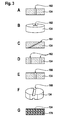
- FIG. 3A a throttle element 134 is shown, which has a straight throttle channel 162.
- FIG. 3B Figure 3 shows a three-dimensional representation of this embodiment.
- a diameter of the straight throttle channel 162 may be 0.2 mm.
- the throttle element 134 can furthermore be configured as a throttle element 134 with an oblique throttle channel 164, FIG. 2C, an at least partially conical throttle channel 166, which can expand toward the pressure sensor element 122, for example.
- FIG. 3E be designed.
- FIG. 3F shows a throttle element 134 with an at least partially perpendicular to an axis of the pressure bore 126 extending throttle channel 168.
- the throttle element 134 may have at least two throttle channels, shown in FIG Figure 3D , In particular, the throttle element 134 may have two straight throttle channels 162. In one embodiment of the throttle element 134 having more than one throttle passage 136, blockage of the throttle element 134 may be prevented.
- FIG. 3G shows a throttle element 134, which is at least partially made of a sintered material, in particular a porous sintered material.
- the throttle element 134 may be at least partially made of a ceramic material.
- the throttle element 134 may have many porous spongy or sieve-like channels 170 by which occurring pressure pulses can be damped.
- An embodiment of the throttle element 134 of non-metallic material is possible in particular by the positive fastening of the throttle element 134 between the discharge nozzle 116 and the carrier element 124.
Landscapes
- Physics & Mathematics (AREA)
- General Physics & Mathematics (AREA)
- Chemical & Material Sciences (AREA)
- Analytical Chemistry (AREA)
- Measuring Fluid Pressure (AREA)
Applications Claiming Priority (1)
| Application Number | Priority Date | Filing Date | Title |
|---|---|---|---|
| DE201310218479 DE102013218479A1 (de) | 2013-09-16 | 2013-09-16 | Vorrichtung zur Erfassung mindestens einer Eigenschaft eines fluiden Mediums |
Publications (2)
| Publication Number | Publication Date |
|---|---|
| EP2853874A2 true EP2853874A2 (fr) | 2015-04-01 |
| EP2853874A3 EP2853874A3 (fr) | 2015-04-22 |
Family
ID=51266169
Family Applications (1)
| Application Number | Title | Priority Date | Filing Date |
|---|---|---|---|
| EP20140179956 Ceased EP2853874A3 (fr) | 2013-09-16 | 2014-08-06 | Dispositif destiné à déterminer au moins une propriété d'un milieu liquide |
Country Status (2)
| Country | Link |
|---|---|
| EP (1) | EP2853874A3 (fr) |
| DE (1) | DE102013218479A1 (fr) |
Cited By (1)
| Publication number | Priority date | Publication date | Assignee | Title |
|---|---|---|---|---|
| CN113811748A (zh) * | 2019-03-18 | 2021-12-17 | 第一传感器移动有限公司 | 具有温度传感器元件的传感器装置和其制造方法 |
Families Citing this family (4)
| Publication number | Priority date | Publication date | Assignee | Title |
|---|---|---|---|---|
| DE102015221153A1 (de) | 2015-10-29 | 2017-05-04 | Robert Bosch Gmbh | Vorrichtung zur Erfassung mindestens einer Eigenschaft eines fluiden Mediums in einem Messgasraum |
| CN106197831B (zh) * | 2016-07-21 | 2022-06-07 | 安徽蓝润自动化仪表有限公司 | 一种流量自动控制型压力表 |
| US11098828B2 (en) * | 2018-12-07 | 2021-08-24 | The Boeing Company | Apparatus and methods for connecting a first electrically conductive tube and a second electrically conductive tube |
| DE102022101817A1 (de) | 2022-01-26 | 2023-07-27 | Danfoss A/S | Druckverbindungsanordnung und Drucksensoranordnung |
Citations (5)
| Publication number | Priority date | Publication date | Assignee | Title |
|---|---|---|---|---|
| US4413524A (en) * | 1982-03-26 | 1983-11-08 | Dresser Industries, Inc. | Pulsation throttling device for a pressure gauge |
| WO2004042338A1 (fr) | 2002-11-05 | 2004-05-21 | Endress + Hauser Gmbh + Co. Kg | Capteur de pression relative pourvu d'un amortisseur cote atmosphere |
| DE102006051192B4 (de) | 2005-10-31 | 2011-02-03 | DENSO CORPORATION, Kariya-shi | Drucksensor |
| US20110198171A1 (en) * | 2010-02-16 | 2011-08-18 | Alexander Lux | Device for reducing pressure pulses in pressure sensors |
| US8117920B2 (en) | 2006-11-22 | 2012-02-21 | Danfoss A/S | Pressure sensor |
Family Cites Families (7)
| Publication number | Priority date | Publication date | Assignee | Title |
|---|---|---|---|---|
| FR2730055B1 (fr) * | 1995-01-30 | 1997-04-04 | Sagem | Capteur de pression de fluide |
| JP3404257B2 (ja) * | 1997-07-11 | 2003-05-06 | 三菱電機株式会社 | 圧力センサ装置 |
| DE10137327A1 (de) * | 2001-07-31 | 2003-02-13 | Honsberg & Co Kg | Drucksensoreinheit |
| DE10232315B4 (de) * | 2001-11-12 | 2009-05-28 | Temperaturmeßtechnik Geraberg GmbH | Kombinierter Temperatur- und Druckfühler und Verfahren zur Ermittlung von physikalischen Kenngrößen |
| JP3870918B2 (ja) * | 2002-10-23 | 2007-01-24 | 株式会社デンソー | 温度センサ一体型圧力センサ装置 |
| DE102004025339B4 (de) * | 2004-05-19 | 2007-09-06 | Ifm Electronic Gmbh | Drucksensor |
| DE102005060651A1 (de) * | 2005-12-19 | 2007-06-28 | Robert Bosch Gmbh | Kombinierter Druck- und Temperatursensor |
-
2013
- 2013-09-16 DE DE201310218479 patent/DE102013218479A1/de not_active Withdrawn
-
2014
- 2014-08-06 EP EP20140179956 patent/EP2853874A3/fr not_active Ceased
Patent Citations (5)
| Publication number | Priority date | Publication date | Assignee | Title |
|---|---|---|---|---|
| US4413524A (en) * | 1982-03-26 | 1983-11-08 | Dresser Industries, Inc. | Pulsation throttling device for a pressure gauge |
| WO2004042338A1 (fr) | 2002-11-05 | 2004-05-21 | Endress + Hauser Gmbh + Co. Kg | Capteur de pression relative pourvu d'un amortisseur cote atmosphere |
| DE102006051192B4 (de) | 2005-10-31 | 2011-02-03 | DENSO CORPORATION, Kariya-shi | Drucksensor |
| US8117920B2 (en) | 2006-11-22 | 2012-02-21 | Danfoss A/S | Pressure sensor |
| US20110198171A1 (en) * | 2010-02-16 | 2011-08-18 | Alexander Lux | Device for reducing pressure pulses in pressure sensors |
Non-Patent Citations (1)
| Title |
|---|
| "Konrad Reif: Sensoren im Kraftfahrzeug", 2012, pages: 134 - 136 |
Cited By (1)
| Publication number | Priority date | Publication date | Assignee | Title |
|---|---|---|---|---|
| CN113811748A (zh) * | 2019-03-18 | 2021-12-17 | 第一传感器移动有限公司 | 具有温度传感器元件的传感器装置和其制造方法 |
Also Published As
| Publication number | Publication date |
|---|---|
| EP2853874A3 (fr) | 2015-04-22 |
| DE102013218479A1 (de) | 2015-03-19 |
Similar Documents
| Publication | Publication Date | Title |
|---|---|---|
| EP2831555B1 (fr) | Sonde pour mesurer une pression et une température | |
| EP2069739B1 (fr) | Capteur enfichable avec mesure combinée de pression et de température | |
| EP0594808B1 (fr) | Dispositif permettant de mesurer la pression et la pression differentielle avec une boite filetee en trois parties et une corniere annulaire | |
| EP2853874A2 (fr) | Dispositif destiné à déterminer au moins une propriété d'un milieu liquide | |
| DE102011088044A1 (de) | Drucksensoranordnung zur Erfassung eines Drucks eines fluiden Mediums in einem Messraum | |
| EP3071942B1 (fr) | Système de capteur de pression permettant de détecter la pression d'un milieu fluide dans une chambre de mesure | |
| DE102015206470A1 (de) | Vorrichtung zum Bestimmen eines Drucks und Verfahren zum Herstellen derselben | |
| WO2003076920A1 (fr) | Systeme de capteur | |
| DE102007000986A1 (de) | Piezoelektrischer Drucksensor | |
| EP1169202A1 (fr) | Dispositif pour mesurer une pression de fluide | |
| DE102014218949A1 (de) | Sensor zur Erfassung eines Drucks eines fluiden Mediums | |
| EP2223066A2 (fr) | Composant pour mesurer une force ou une pression et capteur comprenant un tel composant | |
| EP1704397B1 (fr) | Capteur de pression | |
| DE102016209773A1 (de) | Drosselelement zum Dämpfen von Druckpulsen eines fluiden Mediums in einem Messraum auf einen Drucksensor | |
| DE102013211479A1 (de) | Vorrichtung zur Erfassung eines Drucks und einer Temperatur eines Mediums | |
| EP3236222B1 (fr) | Sonde de temperature et de pression | |
| DE10361769A1 (de) | Druckaufnehmer mit einteiligem Gehäuse | |
| DE102014215752A1 (de) | Sensor zur Erfassung eines Drucks und einer Temperatur eines fluiden Mediums | |
| WO2015197254A1 (fr) | Capteur de pression pour enregistrer la pression d'un milieu fluide dans une chambre de mesure | |
| DE102012207856B4 (de) | Membran für eine Druckmesseinrichtung | |
| DE102014212261A1 (de) | Drucksensor zur Erfassung eines Drucks eines fluiden Mediums in einem Messraum | |
| EP2702378A1 (fr) | Dispositif pour détecter une pression, en particulier une pression de chambre de combustion d'un moteur à combustion interne | |
| EP3418707A1 (fr) | Capteur de pression montable | |
| DE10332284A1 (de) | Drucksensorelement mit integrierter Dichtfläche | |
| WO2012175244A1 (fr) | Détecteur destiné à la détection d'au moins une propriété d'un milieu fluide |
Legal Events
| Date | Code | Title | Description |
|---|---|---|---|
| PUAL | Search report despatched |
Free format text: ORIGINAL CODE: 0009013 |
|
| PUAI | Public reference made under article 153(3) epc to a published international application that has entered the european phase |
Free format text: ORIGINAL CODE: 0009012 |
|
| 17P | Request for examination filed |
Effective date: 20140806 |
|
| AK | Designated contracting states |
Kind code of ref document: A2 Designated state(s): AL AT BE BG CH CY CZ DE DK EE ES FI FR GB GR HR HU IE IS IT LI LT LU LV MC MK MT NL NO PL PT RO RS SE SI SK SM TR |
|
| AX | Request for extension of the european patent |
Extension state: BA ME |
|
| AK | Designated contracting states |
Kind code of ref document: A3 Designated state(s): AL AT BE BG CH CY CZ DE DK EE ES FI FR GB GR HR HU IE IS IT LI LT LU LV MC MK MT NL NO PL PT RO RS SE SI SK SM TR |
|
| AX | Request for extension of the european patent |
Extension state: BA ME |
|
| RIC1 | Information provided on ipc code assigned before grant |
Ipc: G01L 19/00 20060101ALI20150313BHEP Ipc: G01L 19/06 20060101AFI20150313BHEP |
|
| R17P | Request for examination filed (corrected) |
Effective date: 20151022 |
|
| RBV | Designated contracting states (corrected) |
Designated state(s): AL AT BE BG CH CY CZ DE DK EE ES FI FR GB GR HR HU IE IS IT LI LT LU LV MC MK MT NL NO PL PT RO RS SE SI SK SM TR |
|
| 17Q | First examination report despatched |
Effective date: 20160304 |
|
| 18R | Application refused |
Effective date: 20180204 |