EP1704662B1 - Vorrichtung für zeitliche unterabtastung eines otdm-signals, konverter otdm-wdm mit solch einer vorrichtung und wdm-otdm-konverter - Google Patents
Vorrichtung für zeitliche unterabtastung eines otdm-signals, konverter otdm-wdm mit solch einer vorrichtung und wdm-otdm-konverter Download PDFInfo
- Publication number
- EP1704662B1 EP1704662B1 EP04700264.7A EP04700264A EP1704662B1 EP 1704662 B1 EP1704662 B1 EP 1704662B1 EP 04700264 A EP04700264 A EP 04700264A EP 1704662 B1 EP1704662 B1 EP 1704662B1
- Authority
- EP
- European Patent Office
- Prior art keywords
- optical signal
- otdm
- converter
- wavelength
- signal
- Prior art date
- Legal status (The legal status is an assumption and is not a legal conclusion. Google has not performed a legal analysis and makes no representation as to the accuracy of the status listed.)
- Expired - Lifetime
Links
- 230000003287 optical effect Effects 0.000 title claims description 104
- 230000002123 temporal effect Effects 0.000 title claims description 14
- 238000006243 chemical reaction Methods 0.000 claims description 48
- 230000003111 delayed effect Effects 0.000 claims description 10
- 238000005070 sampling Methods 0.000 description 4
- 235000021183 entrée Nutrition 0.000 description 3
- 241001080024 Telles Species 0.000 description 2
- 238000005516 engineering process Methods 0.000 description 2
- 230000007613 environmental effect Effects 0.000 description 2
- 239000000835 fiber Substances 0.000 description 2
- 230000000712 assembly Effects 0.000 description 1
- 238000000429 assembly Methods 0.000 description 1
- 239000002800 charge carrier Substances 0.000 description 1
- 230000008878 coupling Effects 0.000 description 1
- 238000010168 coupling process Methods 0.000 description 1
- 238000005859 coupling reaction Methods 0.000 description 1
- 238000000034 method Methods 0.000 description 1
- 230000001902 propagating effect Effects 0.000 description 1
Images

Classifications
-
- H—ELECTRICITY
- H04—ELECTRIC COMMUNICATION TECHNIQUE
- H04J—MULTIPLEX COMMUNICATION
- H04J14/00—Optical multiplex systems
- H04J14/02—Wavelength-division multiplex systems
- H04J14/0223—Conversion to or from optical TDM
Definitions
- the present invention relates to an OTDM-WDM signal converter comprising such a device and a WDM-OTDM converter.
- An OTDM (Optical Time-Division Multiplexed) type signal is an optical signal resulting from a time multiplexing of original optical signals.
- a Wavelength Division Multiplexed (WDM) type signal is an optical signal resulting from a wavelength division multiplexing of original optical signals.
- Such a sub-sampling device is described in the document entitled “ Simultaneous All-Optical Demultiplexing of a 40-Gb / s Signal to 4 x 10 Gb / s WDM Channels Using an Ultrafast Fiber Wavelength Converter ", by L. Rau et al., Published in IEEE PHOTONICS TECHNOLOGY LETTERS, Volume 14, No. 12, from December 2002 .
- This document describes a time sub-sampling device comprising a wavelength conversion device consisting of a cross-phase modulator associated with a WDM filter, such as a networked waveguide router (of the English "arrayed wave-guide router”).
- This temporal subsampling device is generally difficult to implement and not very robust to environmental disturbances, such as temperature changes, vibrations, etc.
- the invention relates to a converter of a WDM type optical signal into an OTDM type optical signal, the WDM type optical signal consisting of several multiplexed optical signals, each being transmitted at a wavelength of its own, the converter comprising a continuous signal generator emitted at a predetermined conversion wavelength and at least one wavelength converting device receiving as input the continuous signal and the wavelength multiplexed optical signals, for outputting an OTDM optical signal transmitted at a frequency temporal multiple of the common frequency of optical signals multiplexed wavelength.
- Such a converter is described in the document entitled " WDM to OTDM Multiplexing Using an Ultrafast All-Optical Wavelength Converter, by BE Olsson et al., Published in IEEE PHOTONICS TECHNOLOGY LETTERS, Volume 13, No. 9, September 2001 .
- This document describes a WDM-OTDM converter comprising a wavelength conversion device consisting of a cross-phase modulator associated with a filter, such as a Bragg fiber.
- This converter is also difficult to implement and not very robust to environmental disturbances, such as temperature changes, vibrations, etc.
- the document EP1137213 also describes OTDM-WDM and WDM-OTDM converters.
- the aforementioned temporal subsampling device and the converter are also not suitable for OTDM type signals transmitted at frequencies of the order of 160 GHz or more.
- the object of the invention is to overcome these disadvantages by providing a simple and reliable OTDM-WDM converter and WDM-OTDM converter capable of operating for OTDM signals of 160 GHz or higher.
- the subject of the invention is a converter of an OTDM type optical signal into an optical signal of the WDM type, characterized in that it comprises a plurality of temporal subsampling devices as previously described, connected in parallel, each device temporal subsampling circuit comprising a clock pulse generator outputted at a predetermined downsampling frequency and a conversion wavelength specific to the subsampling device, and a wavelength conversion device receiving as input the OTDM optical signal and the clock pulses at the conversion wavelength specific to the subsampling device.
- the subject of the invention is also a converter of an optical signal of the WDM type into an OTDM type optical signal, of the aforementioned type, characterized in that the conversion device comprises on the one hand a linear optical amplifier disposed of for receiving the continuous optical signal and the wavelength division multiplexed optical signals in the opposite direction of propagation, the maximum linear power of the amplifier being set so as to be less than the peak power of the multiplexed optical signals in length wave and on the other hand a phase modulation converter in amplitude modulation.
- the conversion signal which propagates in reverse in the amplifier is not out of phase.
- the conversion signal then carries, in phase modulation, the information carried by the signal to be converted. It then passes through the modulation converter, to carry the information in amplitude modulation, as the signal to be converted.
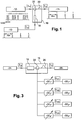
- the temporal subsampling device represented on the figure 1 comprises a generator 10 of clock pulses transmitted at a predetermined subsampling frequency, for example 40 Gb / s. In this way, the transmitted clock pulses are spaced from each other by 25 picoseconds.
- the device further comprises an optical signal receiver 12 of the OTDM type, that is to say resulting from a time multiplexing of optical signals.
- an optical signal receiver 12 of the OTDM type that is to say resulting from a time multiplexing of optical signals.
- This optical signal is transmitted at a frequency of 160 GHz, i.e. the pulses are spaced from each other by 6.25 picoseconds.
- This OTDM type optical signal is intended to be subsampled and converted to the conversion wavelength of the pulse train emitted by the generator 10, to provide, at the output of the temporal subsampling device, one multiplexed signals in the OTDM optical signal.
- the subsampling device comprises a connection interface 14 providing this output signal.
- the subsampling device comprises a wavelength conversion device 16 receiving as input the OTDM type optical signal and the clock pulses supplied by the generator 10.
- the conversion device comprises a linear optical amplifier 18 arranged to receive the OTDM type optical signal and the clock pulses in the opposite direction of propagation.
- a first terminal of the linear optical amplifier 18 is directly connected to the output of the clock pulse generator 10, while a second terminal of this linear optical amplifier is connected to a circulator 22 disposed between the receiver 12 and amplifier 18, so as to direct the OTDM optical signal to this second terminal.
- the maximum linear power of the linear optical amplifier 18 is set to be smaller than the peak power of the OTDM optical signal.
- the wavelength conversion device 16 comprises a phase modulation converter 20 in amplitude modulation.
- the amplitude modulated phase modulation converter is a delayed differential Mach-Zehnder interferometer.
- the circulator 22 is disposed between the linear optical amplifier 18 and this modulation converter, so as to direct the signals leaving the second terminal of the linear optical amplifier to this modulation converter.
- the time signal obtained at the output is a subsampled signal at a quarter of the time frequency of the OTDM type signal, by means of wavelength conversion from ⁇ s to ⁇ H.
- the temporal subsampling device described above can be used to realize an OTDM-WDM converter, as shown on the mounting of the figure 2 .
- wavelength conversion devices 16 1 , 16 2 , 16 3 , 16 4 identical to the device 16 are arranged in parallel and are all connected to the receiver 12.
- Each conversion device 16 i further receives on the first terminal of its linear optical amplifier 18 i , the signal supplied by a generator 10 i of clock pulses emitted at a frequency equal to one quarter of the frequency of the optical signal of the type. OTDM provided by the receiver 12.
- Each clock pulse generator 10 i is shifted by a bit-time corresponding to the frequency of the optical signal OTDM, relative to the clock pulse generator i-1 .
- connection interfaces 14 1 , 14 2 , 14 3 and 14 4 four signals represent a sub-sampling of the OTDM optical signal at a quarter of its frequency. That is, if the OTDM type signal results from the multiplexing of four original time signals, this arrangement makes it possible to output the four signals.
- Each clock pulse generator 10 i generates signals at a wavelength of its own equal to ⁇ Hi .
- ⁇ H1 1544.5 nm
- ⁇ H2 1 546.3 nm
- ⁇ H3 1 548.1 nm
- ⁇ H4 1 549.9 nm.
- the four subsampled signals obtained can then be recombined to obtain a multiplexed signal of the WDM type.
- a converter of an OTDM type optical signal has thus been made into a WDM type optical signal.
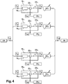
- a WDM-OTDM converter can be realized, as shown on the assembly of the figure 3 according to a first embodiment of the invention.
- the assembly represented in this figure comprises a wavelength conversion device 16 comprising a linear optical amplifier 18, a circulator 22 and a delayed differential Mach-Zehnder interferometer 20.
- the circulator 22, arranged between the linear optical amplifier 18 and the delayed differential Mach-Zehnder interferometer 20 is also connected to means for providing a WDM type optical signal, that is to say an optical signal consisting of several optical signals multiplexed in wavelength, each being transmitted at a wavelength of its own.
- the supply means consist of means 30 1 , 30 2 , 30 3 and 30 4 for receiving the multiplexed optical signals connected in parallel, and each associated with a retarder 32 1 , 32 2 , 32 3 and 32 4 .
- retarders enable the multiplexed optical signals from the means 30 1 , 30 2 , 30 3 and 30 4 to be time-shifted by a time-bit equivalent to the desired multiple frequency at the output of the OTDM-type optical signal.
- this frequency is equal to four times the time frequency of the original multiplexed optical signals, since the WDM signal consists of four original signals.
- connection interface 36 At the output of the WDM-OTDM converter, a connection interface 36 provides an OTDM type optical signal at the desired multiple time frequency and at the wavelength ⁇ s.
- the retarders 32 1 , 32 2 , 32 3 and 32 4 may be arranged at the output of each of the wavelength conversion devices, before the output signals are combined with each other to provide the signal of desired OTDM type.
Landscapes
- Engineering & Computer Science (AREA)
- Computer Networks & Wireless Communication (AREA)
- Signal Processing (AREA)
- Optical Communication System (AREA)
- Optical Modulation, Optical Deflection, Nonlinear Optics, Optical Demodulation, Optical Logic Elements (AREA)
Claims (8)
- Konverter eines optischen OTDM-Signals in ein optisches WDM-Signal, umfassend eine Vielzahl von parallel montierten Vorrichtungen zur zeitlichen Unterabtastung des optischen OTDM-Signals auf einer vorbestimmten Unterabtastfrequenz, wobei jede Vorrichtung zur zeitlichen Unterabtastung umfasst:- einen Generator (101, 102, 103, 104) von Zeitimpulsen, die auf der vorbestimmten Unterabtastfrequenz und mit einer eigenen Konversionswellenlänge λH1, λH2, λH3, λH4) der Unterabtastvorrichtung entsandt werden,- eine Vorrichtung (161, 162, 163, 164) zur Wellenlängenkonversion, die am Eingang das optische OTDM-Signal und die Zeitimpulse mit der eigenen Konversionswellenlänge λH1, λH2, λH3, λH4) der Unterabtastvorrichtung empfängt, um am Ausgang ein unterabgetastetes Signal des optischen Signals mit der Konversionswellenlänge zu liefern, wobei die Konversionsvorrichtung (161, 162, 163, 164) umfasst:* einen linearen optischen Verstärker (181, 182, 183, 184), der derart angeordnet ist, dass er das optische OTDM-Signal und die Zeitimpulse in umgekehrter Ausbreitungsrichtung empfängt, wobei die maximale lineare Leistung des Verstärkers derart eingestellt ist, dass sie niedriger als die Spitzenleistung des optischen OTDM-Signals sein kann,* einen Konverter (201, 202, 203, 204) von Phasenmodulation in Amplitudenmodulation.
- Konverter eines optischen OTDM-Signals in ein optisches WDM-Signal nach Anspruch 1, bei dem der Konverter (201, 202, 203, 204) von Phasenmodulation in Amplitudenmodulation ein verzögertes Mach-Zehnder-Differential-Interferometer umfasst.
- Konverter eines optischen OTDM-Signals in ein optisches WDM-Signal nach Anspruch 1 oder 2, umfassend einen Zirkulator (22), der zwischen dem Verstärker (181, 182, 183, 184) und dem Modulationskonverter (201, 202, 203, 204) derart angeordnet ist, dass er das optische OTDM-Signal zu dem Verstärker (181, 182, 183, 184) und das aus dem Verstärker (181, 182, 183, 184) austretende Signal zu dem Modulationskonverter (201, 202, 203, 204) lenkt.
- Konverter nach einem der Ansprüche 1 bis 3, bei dem jeder Generator von Zeitimpulsen in Bezug zu einem weiteren Generator von Zeitimpulsen um eine Zeit entsprechend der Frequenz des optischen OTDM-Signals versetzt ist.
- Konverter eines optischen WDM-Signals in ein optisches OTDM-Signal, wobei das optische WDM-Signal aus mehreren wellenlängengemultiplexten optischen Signalen besteht, wobei jedes mit einer Wellenlänge, die ihm eigen ist, übertragen wird, umfassend:- einen Generator (34) eines kontinuierlichen Signals, das mit einer vorbestimmten Konversionswellenlänge (λS) entsandt wird,- eine Vielzahl von Vorrichtungen (161, 162, 163, 164) zur Wellenlängenkonversion, die parallel angeordnet sind, wobei jede Konversionsvorrichtung am Eingang das kontinuierliche Signal und eines der wellenlängengemultiplexten optischen Signale empfängt, um am Ausgang an einer Anschlussschnittstelle das optische OTDM-Signal zu liefern, das mit einer multiplen Zeitfrequenz der gemeinsamen Frequenz der wellenlängengemultiplexten optischen Signale entsandt wird, wobei jede Konversionsvorrichtung umfasst:* einen linearen optischen Verstärker (18; 181, 182, 183, 184), der derart angeordnet ist, dass er das kontinuierliche optische Signal und das wellenlängengemultiplexte optische Signal in umgekehrter Ausbreitungsrichtung empfängt, wobei die maximale lineare Leistung des Verstärkers derart eingestellt ist, dass sie niedriger als die Spitzenleistung des wellenlängengemultiplexten optischen Signals sein kann,* einen Konverter von Phasenmodulation in Amplitudenmodulation (20; 201, 202, 203, 204).
- Konverter nach Anspruch 5, umfassend eine Vielzahl von Vorrichtungen für zeitlichen Versatz (321, 322, 323, 324), die jeweils spezifisch mit einer Konversionsvorrichtung (161, 162, 163, 164) verbunden sind.
- Konverter eines optischen WDM-Signals in ein optisches OTDM-Signal nach Anspruch 5 oder 6, bei dem der Konverter (20; 201, 202, 203, 204) von Phasenmodulation in Amplitudenmodulation ein verzögertes Mach-Zehnder-Differential-Interferometer umfasst.
- Konverter eines optischen WDM-Signals in ein optisches OTDM-Signal nach einem der Ansprüche 5 bis 7, umfassend mindestens einen Zirkulator (22; 221, 222, 223, 224), der zwischen jedem Verstärker und jedem Modulationskonverter derart angeordnet ist, dass er die wellenlängengemultiplexten optischen Signale zu dem Verstärker und das aus dem Verstärker austretende Signal zu dem Konverter eines modulierten Signals lenkt.
Applications Claiming Priority (1)
| Application Number | Priority Date | Filing Date | Title |
|---|---|---|---|
| PCT/FR2004/000009 WO2005076508A1 (fr) | 2004-01-06 | 2004-01-06 | Dispositif de sous-echantillonnage temporel d'un signal optique de type otdm, convertisseur otdm-wdm comportant un tel dispositif et convertisseur wdm-otdm |
Publications (2)
| Publication Number | Publication Date |
|---|---|
| EP1704662A1 EP1704662A1 (de) | 2006-09-27 |
| EP1704662B1 true EP1704662B1 (de) | 2016-05-18 |
Family
ID=34834300
Family Applications (1)
| Application Number | Title | Priority Date | Filing Date |
|---|---|---|---|
| EP04700264.7A Expired - Lifetime EP1704662B1 (de) | 2004-01-06 | 2004-01-06 | Vorrichtung für zeitliche unterabtastung eines otdm-signals, konverter otdm-wdm mit solch einer vorrichtung und wdm-otdm-konverter |
Country Status (3)
| Country | Link |
|---|---|
| US (1) | US7885544B2 (de) |
| EP (1) | EP1704662B1 (de) |
| WO (1) | WO2005076508A1 (de) |
Families Citing this family (3)
| Publication number | Priority date | Publication date | Assignee | Title |
|---|---|---|---|---|
| EP2779497B1 (de) * | 2013-03-14 | 2017-05-03 | Danmarks Tekniske Universitet | Volloptisches Regenerationssystem für optische Wellenlängenmultiplex-Kommunikationssysteme |
| EP3999655A4 (de) * | 2019-07-16 | 2023-06-14 | Dexcom, Inc. | Elektrodenanordnungen für analytsensoren |
| GB2601134B (en) * | 2020-11-18 | 2024-10-23 | Cisco Tech Inc | Optical modulator |
Family Cites Families (5)
| Publication number | Priority date | Publication date | Assignee | Title |
|---|---|---|---|---|
| JP2001274772A (ja) * | 2000-03-24 | 2001-10-05 | Kddi Corp | Tdm光多重装置、tdm光分離装置、wdm/tdm変換装置及びtdm/wdm変換装置 |
| US6437905B1 (en) * | 2000-07-07 | 2002-08-20 | Lucent Technologies Inc. | Optical wavelength converter |
| US6832053B2 (en) * | 2000-12-22 | 2004-12-14 | Lucent Technologies Inc. | Delayed interference wavelength converter and/or 2R regenerator |
| WO2003007068A1 (en) | 2001-07-11 | 2003-01-23 | Danmarks Tekniske Universitet | A method and an apparatus for reducing amplitude variations when modulating optical signals in semiconductor based components |
| FR2838836B1 (fr) * | 2002-04-19 | 2004-08-20 | France Telecom | Dispositif optique et procede pour convertir des signaux wdm en un signal otdm, et reciproquement |
-
2004
- 2004-01-06 EP EP04700264.7A patent/EP1704662B1/de not_active Expired - Lifetime
- 2004-01-06 US US10/585,357 patent/US7885544B2/en active Active
- 2004-01-06 WO PCT/FR2004/000009 patent/WO2005076508A1/fr not_active Ceased
Non-Patent Citations (1)
| Title |
|---|
| LEUTHOLD J ET AL: "Linear all-optical wavelength conversion based an linear optical amplifier", OPTICAL FIBER COMMUNICATIONS CONFERENCE. (OFC). POSTCONFERENCE TECHNICAL DIGEST. POSTDEADLINE PAPERS (IEEE CAT. NO.02CH37339) OPT SOC. AMERICA WASHINGTON, DC, USA; [TRENDS IN OPTICS AND PHOTONICS SERIES. (TOPS)], IEEE, vol. TOPS. VOL. 70, 17 March 2002 (2002-03-17), pages 597 - 598, XP010618003, ISBN: 978-1-55752-701-1, DOI: 10.1109/OFC.2002.1036586 * |
Also Published As
| Publication number | Publication date |
|---|---|
| WO2005076508A8 (fr) | 2006-08-17 |
| EP1704662A1 (de) | 2006-09-27 |
| WO2005076508A1 (fr) | 2005-08-18 |
| US20070183710A1 (en) | 2007-08-09 |
| US7885544B2 (en) | 2011-02-08 |
Similar Documents
| Publication | Publication Date | Title |
|---|---|---|
| EP0924552A2 (de) | Opto-electronische Frequenzteilerschaltung und deren Betriebsverfahren | |
| Cao et al. | Optimally-designed single fiber Bragg grating filter scheme for RZ-OOK/DPSK/DQPSK to NRZ-OOK/DPSK/DQPSK format conversion | |
| CN101258699A (zh) | 全光方法和系统 | |
| Tan et al. | Optical Nyquist filtering for elastic OTDM signals: Fundamentals and demonstrations | |
| FR2727771A1 (fr) | Dispositif convertisseur de longueur d'ondes | |
| EP1704662B1 (de) | Vorrichtung für zeitliche unterabtastung eines otdm-signals, konverter otdm-wdm mit solch einer vorrichtung und wdm-otdm-konverter | |
| Myslivets et al. | 1.56-µs continuously tunable parametric delay line for a 40-gb/s signal | |
| EP1087553A1 (de) | Optischer Regenerator für WDM Signalen | |
| US20050226624A1 (en) | Optical pulse position modulation discriminator | |
| JP5633876B2 (ja) | コヒーレント光時分割多重信号の復調方式 | |
| EP1511133B1 (de) | Mehrwellige Lichtquelle | |
| Calabretta et al. | All-optical packet switching and label rewriting for data packets beyond 160 Gb/s | |
| EP1497939A1 (de) | Optische vorrichtung und verfahren zur umwandlung eines wdm-signals in ein otdm-signal und umgekehrt | |
| FR2736480A1 (fr) | Disposif de coloration de signaux optiques | |
| EP1137208B1 (de) | Synchroner optischer Regenerator unter Verwendung von Intensitätsmodulation und Phasenmodulation mit gekreutzen Kerreffekt | |
| Takiguchi et al. | Gate-free integrated-optic tunable filter for demultiplexing various capacity optical OFDM signals | |
| Singh et al. | Optimization and efficient routing scenario of system using C-band: reconfigurable multiwavelength optical cross connect based on tunable fiber Bragg grating and optical circulator | |
| US6388781B1 (en) | Apparatus for time division/wave division conversion | |
| EP1398896A1 (de) | Frequenzkamm für ein Netzwerk mit optischer Frequenzmultiplexierung | |
| TWI299798B (en) | Optical Apparatus and Optical Method | |
| EP1224756B1 (de) | Alternierende phasenmodulation für nicht-soliton rz optische übertragung | |
| EP0859482B1 (de) | Optischer Regenerator für Soliton faseroptische WDM Systeme | |
| EP0924883A1 (de) | Reduktion von kollisionsinduziertem Zeitjitter in einem Wellenlängenmultiplexsolitonübertragungssystem durch Veränderung der Wellenlängen | |
| Vidal et al. | Photonic WDM microwave filter with negative taps | |
| Schneider | Photonics-Assisted Signal Processing Systems Using Parallelization in Time and Frequency Domain |
Legal Events
| Date | Code | Title | Description |
|---|---|---|---|
| PUAI | Public reference made under article 153(3) epc to a published international application that has entered the european phase |
Free format text: ORIGINAL CODE: 0009012 |
|
| 17P | Request for examination filed |
Effective date: 20060801 |
|
| AK | Designated contracting states |
Kind code of ref document: A1 Designated state(s): AT BE BG CH CY CZ DE DK EE ES FI FR GB GR HU IE IT LI LU MC NL PT RO SE SI SK TR |
|
| DAX | Request for extension of the european patent (deleted) | ||
| RAP1 | Party data changed (applicant data changed or rights of an application transferred) |
Owner name: FRANCE TELECOM |
|
| 17Q | First examination report despatched |
Effective date: 20090710 |
|
| RAP1 | Party data changed (applicant data changed or rights of an application transferred) |
Owner name: ORANGE |
|
| GRAP | Despatch of communication of intention to grant a patent |
Free format text: ORIGINAL CODE: EPIDOSNIGR1 |
|
| INTG | Intention to grant announced |
Effective date: 20160122 |
|
| GRAS | Grant fee paid |
Free format text: ORIGINAL CODE: EPIDOSNIGR3 |
|
| GRAA | (expected) grant |
Free format text: ORIGINAL CODE: 0009210 |
|
| AK | Designated contracting states |
Kind code of ref document: B1 Designated state(s): AT BE BG CH CY CZ DE DK EE ES FI FR GB GR HU IE IT LI LU MC NL PT RO SE SI SK TR |
|
| REG | Reference to a national code |
Ref country code: GB Ref legal event code: FG4D Free format text: NOT ENGLISH |
|
| REG | Reference to a national code |
Ref country code: CH Ref legal event code: EP |
|
| REG | Reference to a national code |
Ref country code: IE Ref legal event code: FG4D Free format text: LANGUAGE OF EP DOCUMENT: FRENCH Ref country code: AT Ref legal event code: REF Ref document number: 801260 Country of ref document: AT Kind code of ref document: T Effective date: 20160615 |
|
| REG | Reference to a national code |
Ref country code: DE Ref legal event code: R096 Ref document number: 602004049324 Country of ref document: DE |
|
| REG | Reference to a national code |
Ref country code: NL Ref legal event code: MP Effective date: 20160518 |
|
| PG25 | Lapsed in a contracting state [announced via postgrant information from national office to epo] |
Ref country code: FI Free format text: LAPSE BECAUSE OF FAILURE TO SUBMIT A TRANSLATION OF THE DESCRIPTION OR TO PAY THE FEE WITHIN THE PRESCRIBED TIME-LIMIT Effective date: 20160518 Ref country code: NL Free format text: LAPSE BECAUSE OF FAILURE TO SUBMIT A TRANSLATION OF THE DESCRIPTION OR TO PAY THE FEE WITHIN THE PRESCRIBED TIME-LIMIT Effective date: 20160518 |
|
| REG | Reference to a national code |
Ref country code: AT Ref legal event code: MK05 Ref document number: 801260 Country of ref document: AT Kind code of ref document: T Effective date: 20160518 |
|
| PG25 | Lapsed in a contracting state [announced via postgrant information from national office to epo] |
Ref country code: ES Free format text: LAPSE BECAUSE OF FAILURE TO SUBMIT A TRANSLATION OF THE DESCRIPTION OR TO PAY THE FEE WITHIN THE PRESCRIBED TIME-LIMIT Effective date: 20160518 Ref country code: SE Free format text: LAPSE BECAUSE OF FAILURE TO SUBMIT A TRANSLATION OF THE DESCRIPTION OR TO PAY THE FEE WITHIN THE PRESCRIBED TIME-LIMIT Effective date: 20160518 Ref country code: GR Free format text: LAPSE BECAUSE OF FAILURE TO SUBMIT A TRANSLATION OF THE DESCRIPTION OR TO PAY THE FEE WITHIN THE PRESCRIBED TIME-LIMIT Effective date: 20160819 Ref country code: PT Free format text: LAPSE BECAUSE OF FAILURE TO SUBMIT A TRANSLATION OF THE DESCRIPTION OR TO PAY THE FEE WITHIN THE PRESCRIBED TIME-LIMIT Effective date: 20160919 |
|
| REG | Reference to a national code |
Ref country code: FR Ref legal event code: PLFP Year of fee payment: 14 |
|
| PG25 | Lapsed in a contracting state [announced via postgrant information from national office to epo] |
Ref country code: IT Free format text: LAPSE BECAUSE OF FAILURE TO SUBMIT A TRANSLATION OF THE DESCRIPTION OR TO PAY THE FEE WITHIN THE PRESCRIBED TIME-LIMIT Effective date: 20160518 |
|
| PG25 | Lapsed in a contracting state [announced via postgrant information from national office to epo] |
Ref country code: DK Free format text: LAPSE BECAUSE OF FAILURE TO SUBMIT A TRANSLATION OF THE DESCRIPTION OR TO PAY THE FEE WITHIN THE PRESCRIBED TIME-LIMIT Effective date: 20160518 Ref country code: EE Free format text: LAPSE BECAUSE OF FAILURE TO SUBMIT A TRANSLATION OF THE DESCRIPTION OR TO PAY THE FEE WITHIN THE PRESCRIBED TIME-LIMIT Effective date: 20160518 Ref country code: RO Free format text: LAPSE BECAUSE OF FAILURE TO SUBMIT A TRANSLATION OF THE DESCRIPTION OR TO PAY THE FEE WITHIN THE PRESCRIBED TIME-LIMIT Effective date: 20160518 Ref country code: CZ Free format text: LAPSE BECAUSE OF FAILURE TO SUBMIT A TRANSLATION OF THE DESCRIPTION OR TO PAY THE FEE WITHIN THE PRESCRIBED TIME-LIMIT Effective date: 20160518 Ref country code: SK Free format text: LAPSE BECAUSE OF FAILURE TO SUBMIT A TRANSLATION OF THE DESCRIPTION OR TO PAY THE FEE WITHIN THE PRESCRIBED TIME-LIMIT Effective date: 20160518 |
|
| REG | Reference to a national code |
Ref country code: DE Ref legal event code: R097 Ref document number: 602004049324 Country of ref document: DE |
|
| PG25 | Lapsed in a contracting state [announced via postgrant information from national office to epo] |
Ref country code: AT Free format text: LAPSE BECAUSE OF FAILURE TO SUBMIT A TRANSLATION OF THE DESCRIPTION OR TO PAY THE FEE WITHIN THE PRESCRIBED TIME-LIMIT Effective date: 20160518 |
|
| PLBE | No opposition filed within time limit |
Free format text: ORIGINAL CODE: 0009261 |
|
| STAA | Information on the status of an ep patent application or granted ep patent |
Free format text: STATUS: NO OPPOSITION FILED WITHIN TIME LIMIT |
|
| 26N | No opposition filed |
Effective date: 20170221 |
|
| PG25 | Lapsed in a contracting state [announced via postgrant information from national office to epo] |
Ref country code: SI Free format text: LAPSE BECAUSE OF FAILURE TO SUBMIT A TRANSLATION OF THE DESCRIPTION OR TO PAY THE FEE WITHIN THE PRESCRIBED TIME-LIMIT Effective date: 20160518 Ref country code: BE Free format text: LAPSE BECAUSE OF NON-PAYMENT OF DUE FEES Effective date: 20170131 |
|
| REG | Reference to a national code |
Ref country code: CH Ref legal event code: PL |
|
| PG25 | Lapsed in a contracting state [announced via postgrant information from national office to epo] |
Ref country code: MC Free format text: LAPSE BECAUSE OF FAILURE TO SUBMIT A TRANSLATION OF THE DESCRIPTION OR TO PAY THE FEE WITHIN THE PRESCRIBED TIME-LIMIT Effective date: 20160518 |
|
| PG25 | Lapsed in a contracting state [announced via postgrant information from national office to epo] |
Ref country code: CH Free format text: LAPSE BECAUSE OF NON-PAYMENT OF DUE FEES Effective date: 20170131 Ref country code: LI Free format text: LAPSE BECAUSE OF NON-PAYMENT OF DUE FEES Effective date: 20170131 |
|
| REG | Reference to a national code |
Ref country code: IE Ref legal event code: MM4A |
|
| PG25 | Lapsed in a contracting state [announced via postgrant information from national office to epo] |
Ref country code: LU Free format text: LAPSE BECAUSE OF NON-PAYMENT OF DUE FEES Effective date: 20170106 |
|
| REG | Reference to a national code |
Ref country code: FR Ref legal event code: PLFP Year of fee payment: 15 |
|
| REG | Reference to a national code |
Ref country code: BE Ref legal event code: MM Effective date: 20170131 |
|
| PG25 | Lapsed in a contracting state [announced via postgrant information from national office to epo] |
Ref country code: IE Free format text: LAPSE BECAUSE OF NON-PAYMENT OF DUE FEES Effective date: 20170106 |
|
| PG25 | Lapsed in a contracting state [announced via postgrant information from national office to epo] |
Ref country code: HU Free format text: LAPSE BECAUSE OF FAILURE TO SUBMIT A TRANSLATION OF THE DESCRIPTION OR TO PAY THE FEE WITHIN THE PRESCRIBED TIME-LIMIT; INVALID AB INITIO Effective date: 20040106 |
|
| PG25 | Lapsed in a contracting state [announced via postgrant information from national office to epo] |
Ref country code: BG Free format text: LAPSE BECAUSE OF FAILURE TO SUBMIT A TRANSLATION OF THE DESCRIPTION OR TO PAY THE FEE WITHIN THE PRESCRIBED TIME-LIMIT Effective date: 20160518 |
|
| PG25 | Lapsed in a contracting state [announced via postgrant information from national office to epo] |
Ref country code: CY Free format text: LAPSE BECAUSE OF NON-PAYMENT OF DUE FEES Effective date: 20160518 |
|
| PG25 | Lapsed in a contracting state [announced via postgrant information from national office to epo] |
Ref country code: TR Free format text: LAPSE BECAUSE OF FAILURE TO SUBMIT A TRANSLATION OF THE DESCRIPTION OR TO PAY THE FEE WITHIN THE PRESCRIBED TIME-LIMIT Effective date: 20160518 |
|
| PGFP | Annual fee paid to national office [announced via postgrant information from national office to epo] |
Ref country code: GB Payment date: 20221221 Year of fee payment: 20 Ref country code: FR Payment date: 20221220 Year of fee payment: 20 |
|
| PGFP | Annual fee paid to national office [announced via postgrant information from national office to epo] |
Ref country code: DE Payment date: 20221220 Year of fee payment: 20 |
|
| REG | Reference to a national code |
Ref country code: DE Ref legal event code: R071 Ref document number: 602004049324 Country of ref document: DE |
|
| REG | Reference to a national code |
Ref country code: GB Ref legal event code: PE20 Expiry date: 20240105 |
|
| PG25 | Lapsed in a contracting state [announced via postgrant information from national office to epo] |
Ref country code: GB Free format text: LAPSE BECAUSE OF EXPIRATION OF PROTECTION Effective date: 20240105 |