EP1705009A1 - Automatische vorrichtung zum handhaben und transportieren von druckhülsen - Google Patents
Automatische vorrichtung zum handhaben und transportieren von druckhülsen Download PDFInfo
- Publication number
- EP1705009A1 EP1705009A1 EP04805128A EP04805128A EP1705009A1 EP 1705009 A1 EP1705009 A1 EP 1705009A1 EP 04805128 A EP04805128 A EP 04805128A EP 04805128 A EP04805128 A EP 04805128A EP 1705009 A1 EP1705009 A1 EP 1705009A1
- Authority
- EP
- European Patent Office
- Prior art keywords
- housing
- support
- route
- mobile unit
- basic mobile
- Prior art date
- Legal status (The legal status is an assumption and is not a legal conclusion. Google has not performed a legal analysis and makes no representation as to the accuracy of the status listed.)
- Granted
Links
- 238000006073 displacement reaction Methods 0.000 claims description 37
- 230000000712 assembly Effects 0.000 claims description 23
- 238000000429 assembly Methods 0.000 claims description 23
- 238000012546 transfer Methods 0.000 claims description 19
- 230000004913 activation Effects 0.000 claims description 14
- 238000002347 injection Methods 0.000 claims description 13
- 239000007924 injection Substances 0.000 claims description 13
- 230000033001 locomotion Effects 0.000 claims description 7
- 238000012545 processing Methods 0.000 claims description 7
- 230000008878 coupling Effects 0.000 claims description 5
- 238000010168 coupling process Methods 0.000 claims description 5
- 238000005859 coupling reaction Methods 0.000 claims description 5
- 230000003287 optical effect Effects 0.000 claims description 3
- 230000010339 dilation Effects 0.000 claims 1
- 238000011084 recovery Methods 0.000 claims 1
- 210000003414 extremity Anatomy 0.000 description 29
- 230000003993 interaction Effects 0.000 description 5
- 238000009434 installation Methods 0.000 description 4
- 238000000034 method Methods 0.000 description 4
- 239000011521 glass Substances 0.000 description 3
- 230000001681 protective effect Effects 0.000 description 3
- 230000008859 change Effects 0.000 description 2
- 238000000605 extraction Methods 0.000 description 2
- 238000012423 maintenance Methods 0.000 description 2
- 230000003213 activating effect Effects 0.000 description 1
- 238000007774 anilox coating Methods 0.000 description 1
- 210000000078 claw Anatomy 0.000 description 1
- 238000004140 cleaning Methods 0.000 description 1
- 238000013461 design Methods 0.000 description 1
- 238000011161 development Methods 0.000 description 1
- 230000018109 developmental process Effects 0.000 description 1
- 230000000694 effects Effects 0.000 description 1
- 230000005611 electricity Effects 0.000 description 1
- 239000000463 material Substances 0.000 description 1
- 238000003825 pressing Methods 0.000 description 1
- 210000001364 upper extremity Anatomy 0.000 description 1
Images




Classifications
-
- B—PERFORMING OPERATIONS; TRANSPORTING
- B41—PRINTING; LINING MACHINES; TYPEWRITERS; STAMPS
- B41F—PRINTING MACHINES OR PRESSES
- B41F27/00—Devices for attaching printing elements or formes to supports
- B41F27/12—Devices for attaching printing elements or formes to supports for attaching flexible printing formes
- B41F27/1206—Feeding to or removing from the forme cylinder
-
- B—PERFORMING OPERATIONS; TRANSPORTING
- B41—PRINTING; LINING MACHINES; TYPEWRITERS; STAMPS
- B41F—PRINTING MACHINES OR PRESSES
- B41F13/00—Common details of rotary presses or machines
- B41F13/08—Cylinders
-
- B—PERFORMING OPERATIONS; TRANSPORTING
- B41—PRINTING; LINING MACHINES; TYPEWRITERS; STAMPS
- B41F—PRINTING MACHINES OR PRESSES
- B41F27/00—Devices for attaching printing elements or formes to supports
-
- B—PERFORMING OPERATIONS; TRANSPORTING
- B41—PRINTING; LINING MACHINES; TYPEWRITERS; STAMPS
- B41N—PRINTING PLATES OR FOILS; MATERIALS FOR SURFACES USED IN PRINTING MACHINES FOR PRINTING, INKING, DAMPING, OR THE LIKE; PREPARING SUCH SURFACES FOR USE AND CONSERVING THEM
- B41N6/00—Mounting boards; Sleeves Make-ready devices, e.g. underlays, overlays; Attaching by chemical means, e.g. vulcanising
-
- B—PERFORMING OPERATIONS; TRANSPORTING
- B41—PRINTING; LINING MACHINES; TYPEWRITERS; STAMPS
- B41P—INDEXING SCHEME RELATING TO PRINTING, LINING MACHINES, TYPEWRITERS, AND TO STAMPS
- B41P2200/00—Printing processes
- B41P2200/10—Relief printing
- B41P2200/12—Flexographic printing
-
- B—PERFORMING OPERATIONS; TRANSPORTING
- B41—PRINTING; LINING MACHINES; TYPEWRITERS; STAMPS
- B41P—INDEXING SCHEME RELATING TO PRINTING, LINING MACHINES, TYPEWRITERS, AND TO STAMPS
- B41P2227/00—Mounting or handling printing plates; Forming printing surfaces in situ
- B41P2227/60—Devices for transferring printing plates
Definitions
- This invention relates to an automatic handling and transportation device for a printer housing suitable for use in flexographic printer cylinder changing operations whilst the printer is operating.
- Printing machines are well-known, especially flexographic printing machines which are fitted with a large, central support drum which rotates on a horizontal axis and along which moves a strip of material to be printed and a number of printing clusters are on each side of said support drum.
- Each printing cluster is designed to print, for example, one colour only for which it comprises a printing cylinder bearing a block with the design to be printed and one or more ink-rollers connected to their respective containers of ink of the corresponding colour positioned to ink the corresponding printing cylinder block.
- Both the inking rollers and the printing cylinder are positioned to turn on axes parallel to the axis of the support drum with means provided for moving the printing cylinder laterally into contact with the support drum and the inking rollers into contact with the printing cylinder or for separating them.
- Each block is mounted on a housing which in turn is mounted on a housing-bearing assembly supported at each extremity by existing supports on opposite sides of the printing machine and operated in turn from one of said extremities.
- the latest developments in flexographic printing machines incorporate means for maintaining the respective housing-bearing assembly projecting outwards by one of its extermities to allow the withdrawal of the corresponding block-bearing housing by the opposing extremity by sliding it axially along the assembly and the positioning of a new housing by reversing the procedure when a printing cylinder is separated from the support drum.
- housing-changing operations can be undertaken with the printer in operation they are extremely dangerous for the operator due to the proximity of the moving support drum.
- block-bearing housings can be both large in size and in weight requiring the assistance of a number of workers or the use of lifting devices such as cranes, pulleys etc. adding to the degree of risk with the machine in operation.
- housing-changing operations are undertaken with the machine at rest which brings with it a significant loss of productivity.
- Patent US-A-6644188 describes a procedure for changing housings with the printing machine of the type described above operating.
- such screens do not provide total protection and, taking into account that there are flexographic printers with ten or more print clusters and that a protective screen is required for each one, the means for mounting and dismounting such screens is of great complexity in relation to the low level of protection offered.
- document WO 03/095207 describes a housing-extraction device comprising an instrument in the shape of a glass adapted to fit the frontal extremity of the housing into its open end locating part of the extremity of the housing-bearing assembly inside said glass form and a means of injecting compressed air using various alternative methods, adapted so as to create air pressure in the interior of the glass-shaped instrument able to make the housing slide axially along the length of the housing-bearing assembly in order to extract it.
- a further version is known of where the piston of a pneumatic cylinder attached to the instrument in the form of a glass is what thrusts the assembly to move along the housing.
- an automatic printer housing handling and transportation device characterised by comprising a support to guide and support housings capable of being positioned in alignment with and close to a housing-bearing assembly and an instrument for attachment which can be moved from a transfer position in which the attachment instrument interacts with said housing mounted on the housing-bearing assembly to attach or to free it and a transportation position in which the housing attached by the attachment instrument is on the support.
- the support may have distinct configurations such as, for example, a mandril or cradle and the attachment instrument activated in order to hold the housing by one extremity.
- the attachment instrument when the attachment instrument is displaced, it drags the housing along transferring it from the said housing-bearing assembly which, for example, may be installed in a jutting position on a printing machine, to the support for the device.
- An operation in the reverse direction transfers the housing from the support for the device to the machine's housing-bearing assembly and frees it in the same operation.
- the device comprises a basic mobile unit and means of displacement arranged to move said basic mobile unit on a first route.
- Mounted on said basic mobile unit are one or more handles.
- Each handle includes one of the above-mentioned supports which juts out on a second route, transversal to the previous route and parallel to the said housing-bearing assembly.
- the attachment instrument is connected to a second means of displacement arranged to displace it in the other direction in relation to the support.
- the basic mobile unit is displaced by means of a guide such as, for example, ways arranged horizontally on the first route along a stretch including a first transfer area in which the handling unit mounted on the basic mobile unit is activated to interract with said printing machine and at least one second transfer area in which the basic mobile unit in which the handling unit mounted on the basic mobile unit is activated to interract with the transportation unit or with said storage place.
- a guide such as, for example, ways arranged horizontally on the first route along a stretch including a first transfer area in which the handling unit mounted on the basic mobile unit is activated to interract with said printing machine and at least one second transfer area in which the basic mobile unit in which the handling unit mounted on the basic mobile unit is activated to interract with the transportation unit or with said storage place.
- the handling unit mounted on the basic mobile unit changes over the housings from the printing machine and the transportation unit either by means of a motorised saddle or a self-propelled saddle and that this transportation unit will be specific for moving the housings between said second transfer area and various other places amongst which may be said storage place and a maintenance area where blocks may be changed, cleaning carried out etc.
- the installation may be arranged in such a way that the handling unit mounted on the basic mobile unit exchanges the housings between the printing machine and the storage place or between the printing machine, the storage place and the transportation unit or other combinations.
- the handling unit on the basic mobile unit there is mounted a single handling unit and a third means of displacement is provided, arranged to move the handling unit in relation to the basic mobile unit on a third route, vertical or transversal to either the first or the second route.
- the first, second and third routes correspond respectively to the three orthogonal axes X, Y, Z of a system of Cartesian coordinates where the axes X,Y are horizontal and axis Z is vertical.
- the single support mounted on the handling unit mounted in turn on the basic mobile unit may be positioned in alignment with any housing-bearing assembly on the printing machine or with any support in the storage place or the transportation unit and, by operating the second displacement means a housing may be transferred from the chosen housing-bearing assembly on the printing machine or support in the storage place or the transportation unit to the support on the transportation unit or the support on the handling unit or vice-versa.
- the basic mobile unit on the basic mobile unit are mounted various handling units in fixed positions in which the respective supports are at a height coinciding with the height of various housing-bearing assemblies on the printing machine or supports on the transportation unit or in the storage place.
- the third means of displacement on the vertical route is unnecessary and is not included.
- the said various housing-bearing assemblies of the printing machine comprise all the housing-bearing assemblies on one side of the support drum of the printing machine.
- the handling units mounted on the basic mobile support are useful for changing the housings from one side to the other of the printing machine although each handling unit should be individually lined-up with its corresponding housing-bearing assembly of the printing machine by means of the assembling of the first means of displacement.
- the various housings on one side of the printing machine are transferred sequentially, one after the other, but with minimal displacements of the basic mobile unit carrying-out at the same time, the transfers of the housings between said first and second transfer areas.
- the fixed positions of the various handling units on the basic mobile unit are such that the respective supports may be aligned at once with various housing-bearing assemblies on the printing machine or supports on the transportation unit or the storage place.
- a basic mobile unit may be built on which may be mounted the same number of handling units as printing clusters are arranged around the support drum of the printing machine and in fixed positions such that all the supports on the handling units may be aligned at once with the corresponding housing-bearing assemblies on both sides of the printing machine support drum by a single activation of the first means of displacement.
- a device may also be made with two basic mobile units which will move in opposite directions on the same ways or on different ways and each basic unit will carry as many handling units in fixed, concordant positions as printing assemblies distributed along the corresponding side of the printing machine's support drum with each basic mobile unit responsible for half of the printer's printing clusters.
- the supports on the transportation unit and/or the storage place have to be set out in identical positions relative to the housing-bearing assemblies of the printing machine if it is desired that transfer of all the housings from the handling units to the transportation unit or the storage area, or vice-versa, be carried out in one operation.
- any of the embodiment examples described can be controlled remotely using electronic means which may be programmable by which the automatic housing handling and transport device of this invention permits completely automatic changes of housing operations to be carried out on a printing machine whilst it is in operation without the intervention of the operator.
- the implied risk to the operator of changing housings whilst the machine is in operation is eliminated and, on the other, carrying out a change of housing whether or not the machine is in operation, significantly more quickly than manually even when aided by means for its drawing and lifting.
- the device also permits the carrying out of automatic operations of movement and storage of housings whether or not associated with operations to change housings on the printing machine.
- FIGs. 1 and 2 in which are shown an automatic handling and transportation device for a printer housing according to a first embodiment of the present invention.
- the device comprises a basic mobile unit 10 and a handling unit 30 mounted on said basic mobile unit 10.
- Said basic mobile unit 10 comprises a lower section 13 provided with the first means of displacement which comprise wheels 14 adapted for displacement along 1 which runs on first route X, at least one of the wheels 14 being a tractor wheel operated by motor 11.
- On this lower section 12 there is a raised section 15 on which the handling unit 30 supports.
- the basic mobile unit 10 comprises also an upper section 16 provided with wheels 17 arranged to run along the upper way 3 which also runs on said first route X, that is to say, parallel with lower way 1.
- the upper way 3 has, associated with it, running along its length, an electric current conduit track 43 and control signals and said upper section 16 of the basic mobile unit 10 includes a dynamic power socket 18 to take said electricity supply and control signals from said track 43.
- the control signals remotely control the operation of the device and are emitted by electronic means of remote processing, preferably programmable.
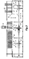
- the handling unit 30 mounted on said basic mobile unit 10 is provided with a support 31, for guiding and supporting the housings which is arranged on a second route Y, transversal to said first route X and parallel to at least one housing-bearing assembly 51 installed in a jutting position on a printing machine 50 (see Fig. 2) or support 71, 81 installed on a transportation unit 70, or in a storage place 80 (see also Fig. 3).
- Said supports 31, 71, 81 have, in the illustrated embodiment examples, the form of a mandril held in a jutting position with an extremity capable of being situated in alignment with said housing-bearing assembly 51 and capable of taking a housing inserted through the axial bore of the same, although this may equally well take the form of a cradle, with one extremity able to be placed in alignment with said housing bearing assembly 51 and to receive a housing supported by means of the cylindrical, external surface of the same.
- an attachment instrument 32 arranged to attach a housing 2 and a second means of displacement 35, 39, 40 adapted to displace the attachment instrument 32 on said second route Y between a transferral position in which the attachment instrument 32 interacts with said housing 2 installed on the housing-bearing assembly 51 (or support 71, 81 of the transportation unit 70 or storage place 80), and a transportation position in which the housing 2, being attached by the attachment instrument 32, is on the support 31.
- Said second means of displacement comprises guide means 40 on the second route Y, placed adjacent to the support 31 and at a distance from the same and a saddle 39 placed to move along the ways 40 being operated by a motor 35.
- the attachment instrument 32 is fixed to the saddle 39 and moves with it.
- the device preferably comprises means of movement 33, 37, 38 adapted to move said support 31 on said second route Y in order to bring its free extremity close to the corresponding free extremity of the housing-bearing assembly 51 (or support 71, 81 of the transportation unit 70 or place of storage 80).
- the support 31 takes the form of a mandril
- the free extremity of the same takes a convex, conical shape fitting into the concave, conical shape formed in the free extremity of the housing-bearing assembly 51, or of the support 71, 81 of the transportation unit 70, or place of storage 80 when this also takes the form of a jutting mandril.
- the means of movement 33, 37, 38 displace the support 31 to fit the tapered end into the tapered bore of the housing-bearing assembly 51, which helps to centre both as shown in Figs. 4 to 6.
- These means of movement 33, 37, 38 comprise guide-ways 38 in the second direction Y, with which is associated a saddle 37 to which is fixed an extremity of the support 31 and a motor 33 connected and adapted to move said saddle 37 along said guide-ways 38.
- said guide-ways 40 of the saddle 39 carrying the attachment instrument 32 are fixed to said saddle 37 carrying the support 31, and move with it.
- the only handling unit 30 is mounted on the basic mobile unit 10 by means of a third means of displacement 44, 45, 46 arranged to move the handling unit 30 in relation to the basic mobile unit 10 on a third route Z, vertically and transversally to the first and second routes X, Y.
- These third means of displacement comprise guide-ways 44, arranged in said third route Z along said elevated section 15 of the basic mobile unit 10 and a saddle 45, on which is mounted the handling unit 30, arranged to run along said guide-ways 44 by a motor 46 connected and arranged for that purpose.
- the support 31 of this single handling unit 30 can be positioned in alignment with any housing-bearing assembly 51 of the printing machine 50, or with any support 71, 81 on the transportation unit 70 or the place of storage 80, by a combined activation of said first and third means of displacement on routes X, Z, and by activating the second means of displacement on route Y, a housing can be transferred from the chosen housing-bearing assembly 50 on the printing machine 50, or support 71, 81 of the transportation unit 70 or from the place of storage 80, to the support 31 of the handling unit 30, or vice-versa.
- the handling unit 30 can be mounted on the basic mobile unit 10 by means of a means of rotation (not shown) arranged to rotate the handling unit 30 in relation to the basic mobile unit 10 around an axis parallel to the third route Z at a certain angle to the second route Y, such as, for example, 90° or 180°. This possibility of rotation gives the device greater versatility.
- FIG. 3 an installation equipped with a device in accordance with this invention is shown where said ways 1, 3, by means of which the basic mobile unit 10, are extended on said first horizontal route X, along a stretch which includes the first transferral area in which the handling unit 30 mounted on the basic mobile unit 10 operates in interaction with a printing machine 50 fitted with several printing clusters around a central support drum 52, a second transferral area in which the handling unit 30 mounted on the basic mobile unit 10 operates in interaction with a transportation unit 70, and a third transferral area where the handling unit 30 mounted on the basic mobile unit 10 operates in interaction with a place of storage 80.
- Said transportation unit 70 comprises a structure with a number of jutting supports 71 each able to hold a housing 2.
- the transportation unit is arranged to be transported by a motorised saddle 72, for instance to a place for maintenance.
- the transportation unit 70 includes a raising and lowering device operated by a means for that purpose and arranged to lower the supports 71 to a level which facilitates the manual handling of the housings 2, and to raise the supports 71 to a level suitable for handling by one or more supports 31 of one or more handling units 30 mounted on the basic mobile unit 10.
- Figs. 4 to 6 are shown a sequence of operations to transfer the housing 2 from the housing-bearing assembly 51 on the printing machine 50 to the support 31, in the form of a mandril on the handling unit 30.
- the support 31 has been aligned with the housing-bearing assembly 51 by operating the first and third means of operation on routes X, Z, and the support 31 has been brought up to and coupled with the housing-bearing assembly 51 by operating the transferral means as described above.
- the second means of displacement on route Y have moved the attachment instrument 32 until it is coupled with the extremity of the housing 2 and in this position the attachment instrument 32 is activated to take hold of the mandril 2 by an activation means 34, 49 which will be described below.
- the second means of displacement are activated in the opposite direction to route Y in order to transfer the housing 2 held by the attachment instrument 32 from the housing-bearing assembly 51 to the support 31.
- the means of transferral can remove the support 31 from the housing-bearing assembly 51 to a prudent distance and the first and third activiation means for routes X, Z can remove the basic mobile unit 10 and the handling unit 30 in order to transfer the housing 2 from the support 31 to a support 71, 81 on the transportation unit 70 or place of storage 80.
- reverse operations are carried out.
- the attachment instrument may be taken from the above description or based upon the description in said patent application WO 03/095207 .
- said attachment instrument 32 is described below and comprises a tubular body 41 with a hollow interior into which is inserted a support 31 in the form of a mandril, such that said tubular body 41 can slide along the support 31, as shown in Fig. 4.
- the tubular body 41 has an external surface situated at an extremity 42 and arranged to couple with an inner surface at one extremity of the housing 2, said internal surface facing a lesser diameter on the housing-bearing assembly 51 (or support 71, 81 of the transportation unit 70 or place of storage 80).
- the housing 2 is slightly longer than a cylindrical support portion on the respective assembly and said external surface of the extremity 42 of the tubular body 41 is sized to couple with the internal surface of the housing 2 which stands proud as shown in Fig. 5.
- Said means of activation of the attachment instrument 32 comprise a first device for injecting air including a first valve (not shown) to selectively connect said bore 34 to a source of compressed air 49, which can include a compressor 49 mounted on the basic mobile unit 10.
- the printer incorporates a second air injection device including a second set of valves arranged to connect injection nozzles located in different positions on the housing-bearing assembly 51 to a source of compressed air. Activation of this second air injection device creates a cushion of air between the housing 2 and the housing-bearing assembly 51 which allows the sliding of the first along the second.
- the first air injection device alternatively works in cooperation with the second to attach the housing 2 by the attachment instrument 32 and slide the housing 2 onto the assembly 5.
- the second injection device begins injecting compressed air between the housing 2 and the assembly 51 to create a cushion of air between the two whilst the second displacement means 35, 39, 40 act to transfer the housing 2, held by the attachment instrument 32, from the assembly 51 to the support 31.
- the same operations are carried out in reverse order.
- claws may be placed which are activated pneumatically or by one or more electric motors to grip corresponding configurations at the extremity of the housing or a rapid coupling of the bearing type with a retractible hose similarly activated or a bayonet type device with rotary activation amongst others.
- the support 71, 81 of the transportation unit 70 or of the place of storage 80 has the same characteristics as the housing-bearing assembly 51 on the printing machine including an injection device analogous to the second injection device described in relation to the housing-bearing assembly 51.
- the storage place 80 is equipped with a compressed air generator and a connection to a source of compressed air to supply the second injection devices fitted to the supports 81, and the second transferral area where the transportation unit 70 is stationed to interact with the handling unit 30 which is equipped with a flexible hose connected to a source of compressed air and fitted with a rapid connector able to be connected manually to an inlet port on the transportation unit 70 to supply the second injection devices fitted to the supports 71 on the same.
- housings bearing print-blocks whether of the type mounted directly on the assembly or those mounted on intermediate housings, to said intermediate housings as well as anilox housings (inkers).
- the attachment instrument 32 on the handling unit 30 will be adapted to the particular characteristics of each housing.
- Figs. 8 and 9 are shown both variants of a second embodiment of the device of the invention characterised by having mounted on the basic mobile unit 10 various handling units 30 in fixed positions in place of the sole handling unit 30 associated with the third means of displacement 44, 45, 46 on the third route Z foreseen in the first embodiment described above.
- said fixed positions in which the handling units 30 are placed are determined so that the respective supports 31 are found at a height which coincides with the height of various housing-bearing assemblies 51 on a printing machine 50 (and supports 71, 81 on the transportation unit 70 or place of storage 80).
- This arrangement allows the third means of displacement on route Z to be discarded with a saving of time in transferral operations at the expense of a lesser flexibility of the device.
- the various supports 31 on the different handling units 30 are found at heights coinciding with the heights of all the housing-bearing assemblies 51 placed on one side of the support drum 52 on the printing machine 50.
- the different handling units 30 on the basic mobile unit 10 are aligned vertically and at heights coinciding with those of all the housing-bearing assemblies 51 placed on each side of the support drum 52 on the printing machine 50.
- the device is able to transfer one after the other all the housings 2 on the printing clusters on one side of the printing machine 50 with short displacements of the basic mobile unit 10 on route X.
- the respective supports 71, 81 will be at heights which coincide with those of the supports 31 on the handling units 30 and similarly vertically aligned.
- the fixed positions of the various handling units 30 mounted on the basic mobile units 10 are such that the respective supports 31 can be aligned at once with various housing-bearing assemblies 51 on the printing machine 50 and advantageously with all of the housing-bearing assemblies 51 on the printing machine 50, that is to say, whether with those arranged on one side as well as the other of the support drum 52.
- the basic mobile unit 10 once the basic mobile unit 10 is in position, all of the housings on the printing clusters on the printing machine 50 can be transferred simultaneously without any further displacement of basic mobile unit 10 on route X.
- the housing-bearing assemblies 71, 81 on the transportation unit 70 and/or the place of storage 80 can be arranged in identical positions relative to the housing-bearing assemblies 51 on the printing machine 50 in order to permit the simultaneous transfer of all the housings 2 between the handling units 30 and the transportation unit 70 and/or the place of storage 80.
- the handling units 30 can be mounted on a giratory structure linked to the basic mobile unit 10 by a means of rotation (not shown) arranged to rotate the giratory structure with all the handling units 30 in relation to the basic mobile unit 10 around an axis parallel to the third route Z and at a certain angle to the second direction Y.
- a support 31 is designed to interact with various housings 2 with different internal diameters.
- Said support 31 is in the form of a jutting mandril with an external diameter equal or inferior to the smallest internal diameter of the various types of housing 2.
- this incorporates at least one radial centring device 47,48 which includes at least one pivoting arm 47 mounted in a cavity 61 on the mandril so that they can girate relative to the respective axes 60.
- An actuator 48 such as a fluo-dynamic cylinder is fitted and connected to activate the pivoting arms 47 in an extended position - the pivoting arms 47 project from the external surface of the support 31 pressing against the internal surface of the housing 2, and in folded position in which the pivoting arms 47 are hidden inside said cavity 61.
- each of the pivoting arms 47 has a wheel 63 mounted at its furthest extremity.
- Said fluo-dynamic cylinder 48 is housed in the cavity 61 and supplied through a bore 62 through the hollow interior of the mandril.
- the device of the present invention comprises also, a positioning device on the first route X (not shown) which is made up of at least one detector chosen from a group which includes a telemeter, a codifier and an optical gauge connected to other electronic processing means arranged to control the operation of said first means of displacement 11, 14.
- Said detector gives a rough position by which said positioning device on the first route X which also includes at least one photo-electric sensor connected to said electronic processing means in order to refine the rough positioning given by said detector.
- the device of the invention comprises a positioning device on the third route Z (not shown) which is made up of a detector chosen from a group which includes a telemeter, a codifier or an optic gauge connected to electronic processing means arranged to control the operation of said third means of displacement 44, 45, 46, and at least one photo-electric sensor connected to said electronic processing means in order to refine the rough positioning given by said detector.
- a detector chosen from a group which includes a telemeter, a codifier or an optic gauge connected to electronic processing means arranged to control the operation of said third means of displacement 44, 45, 46, and at least one photo-electric sensor connected to said electronic processing means in order to refine the rough positioning given by said detector.
Landscapes
- Engineering & Computer Science (AREA)
- Mechanical Engineering (AREA)
- Replacement Of Web Rolls (AREA)
- Treatment Of Fiber Materials (AREA)
- Rotary Presses (AREA)
- Specific Conveyance Elements (AREA)
- Intermediate Stations On Conveyors (AREA)
Applications Claiming Priority (2)
| Application Number | Priority Date | Filing Date | Title |
|---|---|---|---|
| ES200400066A ES2242520B1 (es) | 2004-01-14 | 2004-01-14 | Dispositivo automatico de manipulacion y transporte de camisas de impresion. |
| PCT/ES2004/000585 WO2005068201A1 (es) | 2004-01-14 | 2004-12-29 | Dispositivo automático de manipulación y transporte de camisas de impresión |
Publications (2)
| Publication Number | Publication Date |
|---|---|
| EP1705009A1 true EP1705009A1 (de) | 2006-09-27 |
| EP1705009B1 EP1705009B1 (de) | 2013-01-23 |
Family
ID=34778264
Family Applications (1)
| Application Number | Title | Priority Date | Filing Date |
|---|---|---|---|
| EP04805128A Expired - Lifetime EP1705009B1 (de) | 2004-01-14 | 2004-12-29 | Automatische vorrichtung zum handhaben und transportieren von druckhülsen |
Country Status (5)
| Country | Link |
|---|---|
| US (1) | US7748317B2 (de) |
| EP (1) | EP1705009B1 (de) |
| BR (1) | BRPI0418403A (de) |
| ES (1) | ES2242520B1 (de) |
| WO (1) | WO2005068201A1 (de) |
Cited By (7)
| Publication number | Priority date | Publication date | Assignee | Title |
|---|---|---|---|---|
| WO2009071054A1 (de) | 2007-12-04 | 2009-06-11 | Horst-Walter Hauer | Druckereianlage |
| EP2090432A1 (de) * | 2008-02-12 | 2009-08-19 | Müller Martini Holding AG | Zylinder für ein Druckwerk einer Druckmaschine sowie Verfahren zum Auswechseln einer Druckhülse eines solchen Zylinders |
| EP1776231B2 (de) † | 2004-07-31 | 2011-09-07 | Windmöller & Hölscher KG | Sleevewechselsystem |
| ITFI20130287A1 (it) * | 2013-11-26 | 2015-05-26 | Celli Nonwovens Spa | "sistema per la sostituzione di maniche intercambiabili in macchine da stampa e simili, e relativo metodo" |
| EP3199345A1 (de) | 2016-01-29 | 2017-08-02 | Comexi Group Industries, S.A.U | Druckeinrichtung und verfahren zur anordnung von hülsen in besagter druckeinrichtung |
| IT202200016581A1 (it) * | 2022-08-04 | 2024-02-04 | Uteco Converting Spa | Apparecchiatura per la sostituzione automatica di maniche da stampa. |
| IT202200016587A1 (it) * | 2022-08-04 | 2024-02-04 | Uteco Converting Spa | Apparecchiatura per la sostituzione di maniche da stampa. |
Families Citing this family (5)
| Publication number | Priority date | Publication date | Assignee | Title |
|---|---|---|---|---|
| EP2857200B1 (de) | 2013-10-07 | 2016-03-30 | Neopack, S.L. | Automatische Handhabungs- und Transportvorrichtung für Druckhülsen |
| CN107107524B (zh) * | 2014-12-04 | 2019-05-28 | 鲍勃斯脱梅克斯股份有限公司 | 工具保持头部、输送托架、以及用于安装和移除用于转换平坦基板单元的工具的方法 |
| EP3482939B1 (de) | 2017-11-10 | 2020-05-20 | Exentis Group AG | Siebbereitstellungssystem |
| EP3482934B1 (de) * | 2017-11-10 | 2021-06-30 | Exentis Group AG | 3d-siebdrucksystem zum drucken dreidimensional geformter strukturen |
| BR112023006116A2 (pt) * | 2020-10-19 | 2023-05-09 | Bobst Bielefeld Gmbh | Método para trocar automaticamente luva de ferramenta de impressão |
Family Cites Families (13)
| Publication number | Priority date | Publication date | Assignee | Title |
|---|---|---|---|---|
| GB1581233A (en) * | 1976-06-02 | 1980-12-10 | Drg Uk Ltd | Printing press |
| DE2941521C2 (de) * | 1979-10-12 | 1982-11-25 | Windmöller & Hölscher, 4540 Lengerich | Verfahren zum Austauschen der Formzylinder einer Flexodruckmaschine |
| US4386566A (en) * | 1980-10-06 | 1983-06-07 | Mosstype Corporation | Mandrel assembly for demountable printing cylinder |
| US4520728A (en) * | 1982-02-22 | 1985-06-04 | Paper Converting Machine Company | Method of operating a printing press and apparatus |
| CH686355A5 (fr) * | 1991-04-09 | 1996-03-15 | Bobst Sa | Machine d'impression rotative comprenant un cylindre amovible. |
| US5370047A (en) * | 1993-12-01 | 1994-12-06 | Paper Converting Machine Company | Flexographic press adapted for short runs and method |
| DE4413807C1 (de) * | 1994-04-20 | 1995-09-14 | Windmoeller & Hoelscher | Vorrichtung zum Wechseln der Zylinder an einer Druckmaschine |
| ATE176194T1 (de) * | 1995-10-18 | 1999-02-15 | Fischer & Krecke Gmbh & Co | Vorrichtung zum wechseln von druckzylinderhülsen in druckmaschinen |
| DE19805898C2 (de) * | 1998-02-13 | 2003-09-18 | Roland Man Druckmasch | Druckwerk für eine Rollenrotationsdruckmaschine |
| IT1299666B1 (it) * | 1998-05-05 | 2000-03-24 | Uteco Spa Roto Flexo & Convert | Macchina rotativa flessografica a tamburo centrale a piu' colori |
| ES2258989T5 (es) | 2001-01-04 | 2011-01-17 | FISCHER & KRECKE GMBH & CO. | Procedimiento para cambiar un casquillo de cilindro de impresión y máquina de impresión para la realización de este procedimiento. |
| AU2002302659A1 (en) | 2002-05-10 | 2003-11-11 | Comexi, S.A. | Device for removing printing cylinder sleeves |
| US6796238B2 (en) * | 2002-09-09 | 2004-09-28 | Delaware Capital Formation, Inc. | Plate roll loading and positioning apparatus and method |
-
2004
- 2004-01-14 ES ES200400066A patent/ES2242520B1/es not_active Expired - Fee Related
- 2004-12-29 WO PCT/ES2004/000585 patent/WO2005068201A1/es not_active Ceased
- 2004-12-29 EP EP04805128A patent/EP1705009B1/de not_active Expired - Lifetime
- 2004-12-29 US US10/586,465 patent/US7748317B2/en active Active
- 2004-12-29 BR BRPI0418403-3A patent/BRPI0418403A/pt active Search and Examination
Non-Patent Citations (1)
| Title |
|---|
| See references of WO2005068201A1 * |
Cited By (11)
| Publication number | Priority date | Publication date | Assignee | Title |
|---|---|---|---|---|
| EP1776231B2 (de) † | 2004-07-31 | 2011-09-07 | Windmöller & Hölscher KG | Sleevewechselsystem |
| WO2009071054A1 (de) | 2007-12-04 | 2009-06-11 | Horst-Walter Hauer | Druckereianlage |
| EP2090432A1 (de) * | 2008-02-12 | 2009-08-19 | Müller Martini Holding AG | Zylinder für ein Druckwerk einer Druckmaschine sowie Verfahren zum Auswechseln einer Druckhülse eines solchen Zylinders |
| ITFI20130287A1 (it) * | 2013-11-26 | 2015-05-26 | Celli Nonwovens Spa | "sistema per la sostituzione di maniche intercambiabili in macchine da stampa e simili, e relativo metodo" |
| EP3199345A1 (de) | 2016-01-29 | 2017-08-02 | Comexi Group Industries, S.A.U | Druckeinrichtung und verfahren zur anordnung von hülsen in besagter druckeinrichtung |
| IT202200016581A1 (it) * | 2022-08-04 | 2024-02-04 | Uteco Converting Spa | Apparecchiatura per la sostituzione automatica di maniche da stampa. |
| IT202200016587A1 (it) * | 2022-08-04 | 2024-02-04 | Uteco Converting Spa | Apparecchiatura per la sostituzione di maniche da stampa. |
| EP4316847A1 (de) * | 2022-08-04 | 2024-02-07 | Uteco Converting S.p.A. | Vorrichtung zum auswechseln von druckhülsen |
| EP4316846A1 (de) * | 2022-08-04 | 2024-02-07 | Uteco Converting S.p.A. | Vorrichtung und verfahren zum automatischen wechseln von druckhülsen |
| US20240042752A1 (en) * | 2022-08-04 | 2024-02-08 | Uteco Converting S.P.A. | Apparatus for automatically replacing printing sleeves |
| US12544916B2 (en) | 2022-08-04 | 2026-02-10 | Uteco Converting S.P.A. | Apparatus for automatically replacing printing sleeves |
Also Published As
| Publication number | Publication date |
|---|---|
| ES2242520B1 (es) | 2007-02-16 |
| US7748317B2 (en) | 2010-07-06 |
| WO2005068201A1 (es) | 2005-07-28 |
| US20070214978A1 (en) | 2007-09-20 |
| ES2242520A1 (es) | 2005-11-01 |
| BRPI0418403A (pt) | 2007-05-02 |
| EP1705009B1 (de) | 2013-01-23 |
Similar Documents
| Publication | Publication Date | Title |
|---|---|---|
| US7748317B2 (en) | Automatic handling and transportation device for a printer housing | |
| CA1114880A (en) | Operating table for medical purposes | |
| US20180086046A1 (en) | Sleeve exchange system | |
| US8141239B2 (en) | Drive assembly for a sleeve housing device in a magazine | |
| CN101104375A (zh) | 用于将车轮轮缘安装到车间机械上的主轴 | |
| US8596344B2 (en) | Handling device for pipes | |
| US20170217156A1 (en) | Printing facility and method for sleeves arrangement in said printing facility | |
| US8276633B2 (en) | Labelling machine | |
| US20050252399A1 (en) | Apparatus and method for changing printing sleeves on a printing machine | |
| JPH08108517A (ja) | グラビア印刷機の版胴交換装置 | |
| CN102897248A (zh) | 一种汽车拆解线设备 | |
| CN213384781U (zh) | 机轮检修更换的辅助安装平台 | |
| KR100440721B1 (ko) | 앞바퀴 착륙장치용 장착대 | |
| CN216524618U (zh) | 一种大缸体水密气密打码设备 | |
| US12122145B2 (en) | Method for automatically exchanging a sleeve of a printing tool | |
| CN112518192B (zh) | 一种门架多规格通用自动化焊接定位装置 | |
| JPH0390355A (ja) | グラビア輪転機の版胴交換装置 | |
| US20050166774A1 (en) | Printing machine | |
| ITMO20130128A1 (it) | Macchina per la movimentazione di ruote di veicoli o simili | |
| KR102275590B1 (ko) | 판동 교환 장치 | |
| KR200146648Y1 (ko) | 베어링 분해장치 | |
| CN216611953U (zh) | 对接模块和贴标签机 | |
| JP4601886B2 (ja) | 印刷機内の回転対称な構成部材を交換するための係止装置 | |
| CN202225942U (zh) | 一种汽车拆解线设备 | |
| CN218195146U (zh) | 一种拾取双轮胎辅助夹具工装 |
Legal Events
| Date | Code | Title | Description |
|---|---|---|---|
| PUAI | Public reference made under article 153(3) epc to a published international application that has entered the european phase |
Free format text: ORIGINAL CODE: 0009012 |
|
| 17P | Request for examination filed |
Effective date: 20060529 |
|
| AK | Designated contracting states |
Kind code of ref document: A1 Designated state(s): AT BE BG CH CY CZ DE DK EE ES FI FR GB GR HU IE IS IT LI LT LU MC NL PL PT RO SE SI SK TR |
|
| RIN1 | Information on inventor provided before grant (corrected) |
Inventor name: ESPARCH MARTI, LLUIS Inventor name: ROGER I COLOM, PERECOMEXI, S.A. Inventor name: SAHUN PERES, JORDI Inventor name: PUIG I VILA, JORDI |
|
| DAX | Request for extension of the european patent (deleted) | ||
| 17Q | First examination report despatched |
Effective date: 20090807 |
|
| RAP1 | Party data changed (applicant data changed or rights of an application transferred) |
Owner name: COMEXI GROUP INDUSTRIES, S.A. |
|
| GRAP | Despatch of communication of intention to grant a patent |
Free format text: ORIGINAL CODE: EPIDOSNIGR1 |
|
| GRAS | Grant fee paid |
Free format text: ORIGINAL CODE: EPIDOSNIGR3 |
|
| GRAA | (expected) grant |
Free format text: ORIGINAL CODE: 0009210 |
|
| AK | Designated contracting states |
Kind code of ref document: B1 Designated state(s): AT BE BG CH CY CZ DE DK EE ES FI FR GB GR HU IE IS IT LI LT LU MC NL PL PT RO SE SI SK TR |
|
| REG | Reference to a national code |
Ref country code: GB Ref legal event code: FG4D |
|
| REG | Reference to a national code |
Ref country code: CH Ref legal event code: EP |
|
| REG | Reference to a national code |
Ref country code: CH Ref legal event code: EP Ref country code: AT Ref legal event code: REF Ref document number: 594736 Country of ref document: AT Kind code of ref document: T Effective date: 20130215 |
|
| REG | Reference to a national code |
Ref country code: IE Ref legal event code: FG4D |
|
| REG | Reference to a national code |
Ref country code: DE Ref legal event code: R096 Ref document number: 602004040874 Country of ref document: DE Effective date: 20130321 |
|
| REG | Reference to a national code |
Ref country code: AT Ref legal event code: MK05 Ref document number: 594736 Country of ref document: AT Kind code of ref document: T Effective date: 20130123 |
|
| REG | Reference to a national code |
Ref country code: LT Ref legal event code: MG4D |
|
| REG | Reference to a national code |
Ref country code: NL Ref legal event code: VDEP Effective date: 20130123 |
|
| PG25 | Lapsed in a contracting state [announced via postgrant information from national office to epo] |
Ref country code: AT Free format text: LAPSE BECAUSE OF FAILURE TO SUBMIT A TRANSLATION OF THE DESCRIPTION OR TO PAY THE FEE WITHIN THE PRESCRIBED TIME-LIMIT Effective date: 20130123 Ref country code: LT Free format text: LAPSE BECAUSE OF FAILURE TO SUBMIT A TRANSLATION OF THE DESCRIPTION OR TO PAY THE FEE WITHIN THE PRESCRIBED TIME-LIMIT Effective date: 20130123 Ref country code: BG Free format text: LAPSE BECAUSE OF FAILURE TO SUBMIT A TRANSLATION OF THE DESCRIPTION OR TO PAY THE FEE WITHIN THE PRESCRIBED TIME-LIMIT Effective date: 20130423 Ref country code: IS Free format text: LAPSE BECAUSE OF FAILURE TO SUBMIT A TRANSLATION OF THE DESCRIPTION OR TO PAY THE FEE WITHIN THE PRESCRIBED TIME-LIMIT Effective date: 20130523 Ref country code: ES Free format text: LAPSE BECAUSE OF FAILURE TO SUBMIT A TRANSLATION OF THE DESCRIPTION OR TO PAY THE FEE WITHIN THE PRESCRIBED TIME-LIMIT Effective date: 20130504 Ref country code: BE Free format text: LAPSE BECAUSE OF FAILURE TO SUBMIT A TRANSLATION OF THE DESCRIPTION OR TO PAY THE FEE WITHIN THE PRESCRIBED TIME-LIMIT Effective date: 20130123 Ref country code: SE Free format text: LAPSE BECAUSE OF FAILURE TO SUBMIT A TRANSLATION OF THE DESCRIPTION OR TO PAY THE FEE WITHIN THE PRESCRIBED TIME-LIMIT Effective date: 20130123 |
|
| PG25 | Lapsed in a contracting state [announced via postgrant information from national office to epo] |
Ref country code: FI Free format text: LAPSE BECAUSE OF FAILURE TO SUBMIT A TRANSLATION OF THE DESCRIPTION OR TO PAY THE FEE WITHIN THE PRESCRIBED TIME-LIMIT Effective date: 20130123 Ref country code: PT Free format text: LAPSE BECAUSE OF FAILURE TO SUBMIT A TRANSLATION OF THE DESCRIPTION OR TO PAY THE FEE WITHIN THE PRESCRIBED TIME-LIMIT Effective date: 20130523 Ref country code: SI Free format text: LAPSE BECAUSE OF FAILURE TO SUBMIT A TRANSLATION OF THE DESCRIPTION OR TO PAY THE FEE WITHIN THE PRESCRIBED TIME-LIMIT Effective date: 20130123 Ref country code: NL Free format text: LAPSE BECAUSE OF FAILURE TO SUBMIT A TRANSLATION OF THE DESCRIPTION OR TO PAY THE FEE WITHIN THE PRESCRIBED TIME-LIMIT Effective date: 20130123 Ref country code: PL Free format text: LAPSE BECAUSE OF FAILURE TO SUBMIT A TRANSLATION OF THE DESCRIPTION OR TO PAY THE FEE WITHIN THE PRESCRIBED TIME-LIMIT Effective date: 20130123 Ref country code: GR Free format text: LAPSE BECAUSE OF FAILURE TO SUBMIT A TRANSLATION OF THE DESCRIPTION OR TO PAY THE FEE WITHIN THE PRESCRIBED TIME-LIMIT Effective date: 20130424 |
|
| PG25 | Lapsed in a contracting state [announced via postgrant information from national office to epo] |
Ref country code: RO Free format text: LAPSE BECAUSE OF FAILURE TO SUBMIT A TRANSLATION OF THE DESCRIPTION OR TO PAY THE FEE WITHIN THE PRESCRIBED TIME-LIMIT Effective date: 20130123 Ref country code: DK Free format text: LAPSE BECAUSE OF FAILURE TO SUBMIT A TRANSLATION OF THE DESCRIPTION OR TO PAY THE FEE WITHIN THE PRESCRIBED TIME-LIMIT Effective date: 20130123 Ref country code: SK Free format text: LAPSE BECAUSE OF FAILURE TO SUBMIT A TRANSLATION OF THE DESCRIPTION OR TO PAY THE FEE WITHIN THE PRESCRIBED TIME-LIMIT Effective date: 20130123 Ref country code: CZ Free format text: LAPSE BECAUSE OF FAILURE TO SUBMIT A TRANSLATION OF THE DESCRIPTION OR TO PAY THE FEE WITHIN THE PRESCRIBED TIME-LIMIT Effective date: 20130123 Ref country code: EE Free format text: LAPSE BECAUSE OF FAILURE TO SUBMIT A TRANSLATION OF THE DESCRIPTION OR TO PAY THE FEE WITHIN THE PRESCRIBED TIME-LIMIT Effective date: 20130123 |
|
| PG25 | Lapsed in a contracting state [announced via postgrant information from national office to epo] |
Ref country code: CY Free format text: LAPSE BECAUSE OF FAILURE TO SUBMIT A TRANSLATION OF THE DESCRIPTION OR TO PAY THE FEE WITHIN THE PRESCRIBED TIME-LIMIT Effective date: 20130123 |
|
| PLBE | No opposition filed within time limit |
Free format text: ORIGINAL CODE: 0009261 |
|
| STAA | Information on the status of an ep patent application or granted ep patent |
Free format text: STATUS: NO OPPOSITION FILED WITHIN TIME LIMIT |
|
| PG25 | Lapsed in a contracting state [announced via postgrant information from national office to epo] |
Ref country code: IT Free format text: LAPSE BECAUSE OF FAILURE TO SUBMIT A TRANSLATION OF THE DESCRIPTION OR TO PAY THE FEE WITHIN THE PRESCRIBED TIME-LIMIT Effective date: 20130123 |
|
| 26N | No opposition filed |
Effective date: 20131024 |
|
| REG | Reference to a national code |
Ref country code: DE Ref legal event code: R097 Ref document number: 602004040874 Country of ref document: DE Effective date: 20131024 |
|
| PG25 | Lapsed in a contracting state [announced via postgrant information from national office to epo] |
Ref country code: MC Free format text: LAPSE BECAUSE OF FAILURE TO SUBMIT A TRANSLATION OF THE DESCRIPTION OR TO PAY THE FEE WITHIN THE PRESCRIBED TIME-LIMIT Effective date: 20130123 |
|
| REG | Reference to a national code |
Ref country code: CH Ref legal event code: PL |
|
| GBPC | Gb: european patent ceased through non-payment of renewal fee |
Effective date: 20131229 |
|
| PG25 | Lapsed in a contracting state [announced via postgrant information from national office to epo] |
Ref country code: LU Free format text: LAPSE BECAUSE OF FAILURE TO SUBMIT A TRANSLATION OF THE DESCRIPTION OR TO PAY THE FEE WITHIN THE PRESCRIBED TIME-LIMIT Effective date: 20131229 |
|
| REG | Reference to a national code |
Ref country code: IE Ref legal event code: MM4A |
|
| REG | Reference to a national code |
Ref country code: FR Ref legal event code: ST Effective date: 20140829 |
|
| PG25 | Lapsed in a contracting state [announced via postgrant information from national office to epo] |
Ref country code: IE Free format text: LAPSE BECAUSE OF NON-PAYMENT OF DUE FEES Effective date: 20131229 Ref country code: CH Free format text: LAPSE BECAUSE OF NON-PAYMENT OF DUE FEES Effective date: 20131231 Ref country code: LI Free format text: LAPSE BECAUSE OF NON-PAYMENT OF DUE FEES Effective date: 20131231 |
|
| PG25 | Lapsed in a contracting state [announced via postgrant information from national office to epo] |
Ref country code: FR Free format text: LAPSE BECAUSE OF NON-PAYMENT OF DUE FEES Effective date: 20131231 Ref country code: GB Free format text: LAPSE BECAUSE OF NON-PAYMENT OF DUE FEES Effective date: 20131229 |
|
| PG25 | Lapsed in a contracting state [announced via postgrant information from national office to epo] |
Ref country code: TR Free format text: LAPSE BECAUSE OF FAILURE TO SUBMIT A TRANSLATION OF THE DESCRIPTION OR TO PAY THE FEE WITHIN THE PRESCRIBED TIME-LIMIT Effective date: 20130123 |
|
| PG25 | Lapsed in a contracting state [announced via postgrant information from national office to epo] |
Ref country code: HU Free format text: LAPSE BECAUSE OF FAILURE TO SUBMIT A TRANSLATION OF THE DESCRIPTION OR TO PAY THE FEE WITHIN THE PRESCRIBED TIME-LIMIT; INVALID AB INITIO Effective date: 20041229 |
|
| P01 | Opt-out of the competence of the unified patent court (upc) registered |
Effective date: 20230419 |
|
| PGFP | Annual fee paid to national office [announced via postgrant information from national office to epo] |
Ref country code: DE Payment date: 20240130 Year of fee payment: 20 |
|
| REG | Reference to a national code |
Ref country code: DE Ref legal event code: R071 Ref document number: 602004040874 Country of ref document: DE |