EP1707237A2 - Dispositif et procédé pour la réduction de susceptibilité chez un dispositif médical implantable active aux procédés médicaux comme l'imagerie par résonance magnétique - Google Patents
Dispositif et procédé pour la réduction de susceptibilité chez un dispositif médical implantable active aux procédés médicaux comme l'imagerie par résonance magnétique Download PDFInfo
- Publication number
- EP1707237A2 EP1707237A2 EP06002818A EP06002818A EP1707237A2 EP 1707237 A2 EP1707237 A2 EP 1707237A2 EP 06002818 A EP06002818 A EP 06002818A EP 06002818 A EP06002818 A EP 06002818A EP 1707237 A2 EP1707237 A2 EP 1707237A2
- Authority
- EP
- European Patent Office
- Prior art keywords
- assembly
- conductive
- insulator
- feedthrough
- magnetic shield
- Prior art date
- Legal status (The legal status is an assumption and is not a legal conclusion. Google has not performed a legal analysis and makes no representation as to the accuracy of the status listed.)
- Withdrawn
Links
- 238000002595 magnetic resonance imaging Methods 0.000 title abstract description 70
- 238000000034 method Methods 0.000 title abstract description 14
- 230000005291 magnetic effect Effects 0.000 claims abstract description 137
- 239000003990 capacitor Substances 0.000 claims abstract description 129
- 239000012212 insulator Substances 0.000 claims abstract description 77
- 229910000859 α-Fe Inorganic materials 0.000 claims abstract description 47
- PXHVJJICTQNCMI-UHFFFAOYSA-N Nickel Chemical compound [Ni] PXHVJJICTQNCMI-UHFFFAOYSA-N 0.000 claims description 42
- WABPQHHGFIMREM-UHFFFAOYSA-N lead(0) Chemical compound [Pb] WABPQHHGFIMREM-UHFFFAOYSA-N 0.000 claims description 41
- 230000000747 cardiac effect Effects 0.000 claims description 22
- 239000000463 material Substances 0.000 claims description 21
- 229910052759 nickel Inorganic materials 0.000 claims description 21
- 239000007943 implant Substances 0.000 claims description 12
- NOESYZHRGYRDHS-UHFFFAOYSA-N insulin Chemical compound N1C(=O)C(NC(=O)C(CCC(N)=O)NC(=O)C(CCC(O)=O)NC(=O)C(C(C)C)NC(=O)C(NC(=O)CN)C(C)CC)CSSCC(C(NC(CO)C(=O)NC(CC(C)C)C(=O)NC(CC=2C=CC(O)=CC=2)C(=O)NC(CCC(N)=O)C(=O)NC(CC(C)C)C(=O)NC(CCC(O)=O)C(=O)NC(CC(N)=O)C(=O)NC(CC=2C=CC(O)=CC=2)C(=O)NC(CSSCC(NC(=O)C(C(C)C)NC(=O)C(CC(C)C)NC(=O)C(CC=2C=CC(O)=CC=2)NC(=O)C(CC(C)C)NC(=O)C(C)NC(=O)C(CCC(O)=O)NC(=O)C(C(C)C)NC(=O)C(CC(C)C)NC(=O)C(CC=2NC=NC=2)NC(=O)C(CO)NC(=O)CNC2=O)C(=O)NCC(=O)NC(CCC(O)=O)C(=O)NC(CCCNC(N)=N)C(=O)NCC(=O)NC(CC=3C=CC=CC=3)C(=O)NC(CC=3C=CC=CC=3)C(=O)NC(CC=3C=CC(O)=CC=3)C(=O)NC(C(C)O)C(=O)N3C(CCC3)C(=O)NC(CCCCN)C(=O)NC(C)C(O)=O)C(=O)NC(CC(N)=O)C(O)=O)=O)NC(=O)C(C(C)CC)NC(=O)C(CO)NC(=O)C(C(C)O)NC(=O)C1CSSCC2NC(=O)C(CC(C)C)NC(=O)C(NC(=O)C(CCC(N)=O)NC(=O)C(CC(N)=O)NC(=O)C(NC(=O)C(N)CC=1C=CC=CC=1)C(C)C)CC1=CN=CN1 NOESYZHRGYRDHS-UHFFFAOYSA-N 0.000 claims description 10
- 239000003302 ferromagnetic material Substances 0.000 claims description 9
- CWYNVVGOOAEACU-UHFFFAOYSA-N Fe2+ Chemical compound [Fe+2] CWYNVVGOOAEACU-UHFFFAOYSA-N 0.000 claims description 7
- 229910000990 Ni alloy Inorganic materials 0.000 claims description 6
- 239000003814 drug Substances 0.000 claims description 6
- 206010007559 Cardiac failure congestive Diseases 0.000 claims description 5
- 206010019280 Heart failures Diseases 0.000 claims description 5
- 206010021639 Incontinence Diseases 0.000 claims description 5
- 102000004877 Insulin Human genes 0.000 claims description 5
- 108090001061 Insulin Proteins 0.000 claims description 5
- UELITFHSCLAHKR-UHFFFAOYSA-N acibenzolar-S-methyl Chemical compound CSC(=O)C1=CC=CC2=C1SN=N2 UELITFHSCLAHKR-UHFFFAOYSA-N 0.000 claims description 5
- 230000008468 bone growth Effects 0.000 claims description 5
- 210000004556 brain Anatomy 0.000 claims description 5
- 230000008878 coupling Effects 0.000 claims description 5
- 238000010168 coupling process Methods 0.000 claims description 5
- 238000005859 coupling reaction Methods 0.000 claims description 5
- 229940079593 drug Drugs 0.000 claims description 5
- 230000002496 gastric effect Effects 0.000 claims description 5
- 239000003324 growth hormone secretagogue Substances 0.000 claims description 5
- 229940125396 insulin Drugs 0.000 claims description 5
- 239000011858 nanopowder Substances 0.000 claims description 5
- 210000000278 spinal cord Anatomy 0.000 claims description 5
- 210000001186 vagus nerve Anatomy 0.000 claims description 5
- 230000002861 ventricular Effects 0.000 claims description 5
- 238000001465 metallisation Methods 0.000 description 18
- 230000003068 static effect Effects 0.000 description 17
- 210000001519 tissue Anatomy 0.000 description 17
- 235000014676 Phragmites communis Nutrition 0.000 description 15
- 238000010438 heat treatment Methods 0.000 description 15
- 210000001124 body fluid Anatomy 0.000 description 14
- 239000010839 body fluid Substances 0.000 description 14
- 230000000694 effects Effects 0.000 description 8
- 208000030990 Impulse-control disease Diseases 0.000 description 7
- 230000008901 benefit Effects 0.000 description 6
- PCHJSUWPFVWCPO-UHFFFAOYSA-N gold Chemical compound [Au] PCHJSUWPFVWCPO-UHFFFAOYSA-N 0.000 description 6
- 239000010931 gold Substances 0.000 description 6
- 229910052737 gold Inorganic materials 0.000 description 6
- PNEYBMLMFCGWSK-UHFFFAOYSA-N aluminium oxide Inorganic materials [O-2].[O-2].[O-2].[Al+3].[Al+3] PNEYBMLMFCGWSK-UHFFFAOYSA-N 0.000 description 5
- 238000010586 diagram Methods 0.000 description 5
- 229910000679 solder Inorganic materials 0.000 description 5
- 230000000712 assembly Effects 0.000 description 4
- 238000000429 assembly Methods 0.000 description 4
- 230000001413 cellular effect Effects 0.000 description 4
- 239000004020 conductor Substances 0.000 description 4
- 238000001914 filtration Methods 0.000 description 4
- 230000006870 function Effects 0.000 description 4
- 229910052751 metal Inorganic materials 0.000 description 4
- 239000002184 metal Substances 0.000 description 4
- 230000004044 response Effects 0.000 description 4
- 239000004642 Polyimide Substances 0.000 description 3
- 238000002679 ablation Methods 0.000 description 3
- 230000008859 change Effects 0.000 description 3
- 230000006378 damage Effects 0.000 description 3
- 238000006073 displacement reaction Methods 0.000 description 3
- 230000005672 electromagnetic field Effects 0.000 description 3
- 230000005294 ferromagnetic effect Effects 0.000 description 3
- 238000003384 imaging method Methods 0.000 description 3
- 238000004519 manufacturing process Methods 0.000 description 3
- 238000005259 measurement Methods 0.000 description 3
- 230000002107 myocardial effect Effects 0.000 description 3
- 229920001721 polyimide Polymers 0.000 description 3
- 230000008672 reprogramming Effects 0.000 description 3
- 229920006395 saturated elastomer Polymers 0.000 description 3
- 238000002560 therapeutic procedure Methods 0.000 description 3
- 239000004593 Epoxy Substances 0.000 description 2
- 230000005355 Hall effect Effects 0.000 description 2
- 206010047281 Ventricular arrhythmia Diseases 0.000 description 2
- 230000003187 abdominal effect Effects 0.000 description 2
- 230000004075 alteration Effects 0.000 description 2
- 230000005540 biological transmission Effects 0.000 description 2
- 239000000919 ceramic Substances 0.000 description 2
- 229910010293 ceramic material Inorganic materials 0.000 description 2
- 210000000038 chest Anatomy 0.000 description 2
- 238000013461 design Methods 0.000 description 2
- 238000005516 engineering process Methods 0.000 description 2
- 238000011156 evaluation Methods 0.000 description 2
- 239000011521 glass Substances 0.000 description 2
- 230000001939 inductive effect Effects 0.000 description 2
- 238000009413 insulation Methods 0.000 description 2
- 239000000696 magnetic material Substances 0.000 description 2
- 230000007246 mechanism Effects 0.000 description 2
- 239000002245 particle Substances 0.000 description 2
- 210000005241 right ventricle Anatomy 0.000 description 2
- 230000035939 shock Effects 0.000 description 2
- 239000000758 substrate Substances 0.000 description 2
- 238000012360 testing method Methods 0.000 description 2
- 239000013598 vector Substances 0.000 description 2
- 208000003663 ventricular fibrillation Diseases 0.000 description 2
- 208000033988 Device pacing issue Diseases 0.000 description 1
- 206010015856 Extrasystoles Diseases 0.000 description 1
- 206010028980 Neoplasm Diseases 0.000 description 1
- 208000001871 Tachycardia Diseases 0.000 description 1
- RTAQQCXQSZGOHL-UHFFFAOYSA-N Titanium Chemical compound [Ti] RTAQQCXQSZGOHL-UHFFFAOYSA-N 0.000 description 1
- 206010065341 Ventricular tachyarrhythmia Diseases 0.000 description 1
- 230000009471 action Effects 0.000 description 1
- 239000000853 adhesive Substances 0.000 description 1
- 230000001070 adhesive effect Effects 0.000 description 1
- 210000003484 anatomy Anatomy 0.000 description 1
- 206010003119 arrhythmia Diseases 0.000 description 1
- 230000006793 arrhythmia Effects 0.000 description 1
- 239000010953 base metal Substances 0.000 description 1
- 238000005219 brazing Methods 0.000 description 1
- 206010061592 cardiac fibrillation Diseases 0.000 description 1
- 238000013194 cardioversion Methods 0.000 description 1
- 230000006835 compression Effects 0.000 description 1
- 238000007906 compression Methods 0.000 description 1
- 229920001940 conductive polymer Polymers 0.000 description 1
- 238000013016 damping Methods 0.000 description 1
- 230000001419 dependent effect Effects 0.000 description 1
- 238000000151 deposition Methods 0.000 description 1
- 230000008021 deposition Effects 0.000 description 1
- 238000001514 detection method Methods 0.000 description 1
- 238000002405 diagnostic procedure Methods 0.000 description 1
- 230000005684 electric field Effects 0.000 description 1
- 238000009713 electroplating Methods 0.000 description 1
- 238000004146 energy storage Methods 0.000 description 1
- 230000007613 environmental effect Effects 0.000 description 1
- 125000003700 epoxy group Chemical group 0.000 description 1
- -1 ferrous metals Chemical class 0.000 description 1
- 230000002600 fibrillogenic effect Effects 0.000 description 1
- 238000010304 firing Methods 0.000 description 1
- 231100001261 hazardous Toxicity 0.000 description 1
- 230000036039 immunity Effects 0.000 description 1
- 238000001453 impedance spectrum Methods 0.000 description 1
- 230000006872 improvement Effects 0.000 description 1
- 239000011810 insulating material Substances 0.000 description 1
- 238000005304 joining Methods 0.000 description 1
- 230000004807 localization Effects 0.000 description 1
- 230000007774 longterm Effects 0.000 description 1
- 208000020816 lung neoplasm Diseases 0.000 description 1
- 230000005415 magnetization Effects 0.000 description 1
- 230000007257 malfunction Effects 0.000 description 1
- 239000000203 mixture Substances 0.000 description 1
- 238000012986 modification Methods 0.000 description 1
- 230000004048 modification Effects 0.000 description 1
- 238000012544 monitoring process Methods 0.000 description 1
- 208000031225 myocardial ischemia Diseases 0.000 description 1
- 239000002086 nanomaterial Substances 0.000 description 1
- 239000002105 nanoparticle Substances 0.000 description 1
- 230000017074 necrotic cell death Effects 0.000 description 1
- 239000012811 non-conductive material Substances 0.000 description 1
- 238000001208 nuclear magnetic resonance pulse sequence Methods 0.000 description 1
- 210000000056 organ Anatomy 0.000 description 1
- 238000013021 overheating Methods 0.000 description 1
- 230000035515 penetration Effects 0.000 description 1
- 230000002093 peripheral effect Effects 0.000 description 1
- 230000035699 permeability Effects 0.000 description 1
- 238000007747 plating Methods 0.000 description 1
- 229920000647 polyepoxide Polymers 0.000 description 1
- 230000035755 proliferation Effects 0.000 description 1
- 238000000718 qrs complex Methods 0.000 description 1
- 238000012552 review Methods 0.000 description 1
- 230000033764 rhythmic process Effects 0.000 description 1
- 238000009738 saturating Methods 0.000 description 1
- 231100000241 scar Toxicity 0.000 description 1
- 230000035945 sensitivity Effects 0.000 description 1
- 238000000926 separation method Methods 0.000 description 1
- 238000002633 shock therapy Methods 0.000 description 1
- 239000007787 solid Substances 0.000 description 1
- 238000004544 sputter deposition Methods 0.000 description 1
- 230000000638 stimulation Effects 0.000 description 1
- 238000001356 surgical procedure Methods 0.000 description 1
- 230000001360 synchronised effect Effects 0.000 description 1
- 230000000451 tissue damage Effects 0.000 description 1
- 231100000827 tissue damage Toxicity 0.000 description 1
- 239000010936 titanium Substances 0.000 description 1
- 229910052719 titanium Inorganic materials 0.000 description 1
- 230000002792 vascular Effects 0.000 description 1
- 206010047302 ventricular tachycardia Diseases 0.000 description 1
Images


Classifications
-
- H—ELECTRICITY
- H01—ELECTRIC ELEMENTS
- H01G—CAPACITORS; CAPACITORS, RECTIFIERS, DETECTORS, SWITCHING DEVICES, LIGHT-SENSITIVE OR TEMPERATURE-SENSITIVE DEVICES OF THE ELECTROLYTIC TYPE
- H01G4/00—Fixed capacitors; Processes of their manufacture
- H01G4/35—Feed-through capacitors or anti-noise capacitors
-
- A—HUMAN NECESSITIES
- A61—MEDICAL OR VETERINARY SCIENCE; HYGIENE
- A61N—ELECTROTHERAPY; MAGNETOTHERAPY; RADIATION THERAPY; ULTRASOUND THERAPY
- A61N1/00—Electrotherapy; Circuits therefor
- A61N1/18—Applying electric currents by contact electrodes
- A61N1/32—Applying electric currents by contact electrodes alternating or intermittent currents
- A61N1/36—Applying electric currents by contact electrodes alternating or intermittent currents for stimulation
- A61N1/372—Arrangements in connection with the implantation of stimulators
- A61N1/375—Constructional arrangements, e.g. casings
- A61N1/3752—Details of casing-lead connections
- A61N1/3754—Feedthroughs
-
- H—ELECTRICITY
- H01—ELECTRIC ELEMENTS
- H01G—CAPACITORS; CAPACITORS, RECTIFIERS, DETECTORS, SWITCHING DEVICES, LIGHT-SENSITIVE OR TEMPERATURE-SENSITIVE DEVICES OF THE ELECTROLYTIC TYPE
- H01G4/00—Fixed capacitors; Processes of their manufacture
- H01G4/002—Details
- H01G4/228—Terminals
- H01G4/232—Terminals electrically connecting two or more layers of a stacked or rolled capacitor
-
- H—ELECTRICITY
- H01—ELECTRIC ELEMENTS
- H01F—MAGNETS; INDUCTANCES; TRANSFORMERS; SELECTION OF MATERIALS FOR THEIR MAGNETIC PROPERTIES
- H01F17/00—Fixed inductances of the signal type
- H01F17/04—Fixed inductances of the signal type with magnetic core
- H01F17/06—Fixed inductances of the signal type with magnetic core with core substantially closed in itself, e.g. toroid
- H01F2017/067—Core with two or more holes to lead through conductor
-
- H—ELECTRICITY
- H03—ELECTRONIC CIRCUITRY
- H03H—IMPEDANCE NETWORKS, e.g. RESONANT CIRCUITS; RESONATORS
- H03H1/00—Constructional details of impedance networks whose electrical mode of operation is not specified or applicable to more than one type of network
- H03H2001/0014—Capacitor filters, i.e. capacitors whose parasitic inductance is of relevance to consider it as filter
Definitions
- This invention relates generally to EMI filter assemblies, particularly of the type used in active implantable medical devices (AIMD S ) such as cardiac pacemakers, cardioverter defibrillators, neurostimulators and the like, which decouple and shield internal electronic components of the medical device from undesirable electromagnetic interference (EMI) signals.
- AIMD S active implantable medical devices
- EMI undesirable electromagnetic interference
- the literature indicates a number of precautions that physicians should take in this case, including limiting the power of the MRI magnetic field, programming the pacemaker to fixed or asynchronous pacing mode, and then careful reprogramming and evaluation of the pacemaker and patient after the procedure is complete. There have been reports of latent problems with cardiac pacemakers after an MRI procedure occurring many days later.
- the first type is the main static magnetic field which is used to align protons in body tissue.
- the field strength varies from 0.5 to 3.0 Tesla in most of the currently available MRI units in clinical use. Some of the newer MRI system fields can go as high as 4 to 5 Tesla. This is about 100,000 times the magnetic field strength of the earth.
- a static magnetic field can induce powerful mechanical forces on any magnetic materials implanted within the patient. This would include certain components within the cardiac pacemaker itself and or lead wire systems. It is not likely (other than sudden system shut down) that the static MRI magnetic field can induce currents into the pacemaker lead wire system and hence into the pacemaker itself. It is a basic principle of physics that a magnetic field must either be time-varying as it cuts across the conductor, or the conductor itself must move within the magnetic field for currents to be induced.
- the second type of field produced by magnetic resonance imaging is the pulsed RF field which is generated by the body coil or head coil. This is used to change the energy state of the protons and illicit MRI signals from tissue.
- the RF field is homogeneous in the central region and has two main components: (1) the magnetic field is circularly polarized in the actual plane; and (2) the electric field is related to the magnetic field by Maxwell's equations.
- the RF field is switched on and off during measurements and usually has a frequency of 21 MHz to 64 MHz to 128 MHz depending upon the static magnetic field strength.
- the third type of electromagnetic field is the time-varying magnetic gradient fields which are used for spatial localization. These change their strength along different orientations and operating frequencies on the order of 1 kHz.
- the vectors of the magnetic field gradients in the X, Y and Z directions are produced by three sets of orthogonally positioned coils and are switched on only during the measurements.
- Feedthrough terminal pin assemblies are generally well known in the art for use in connecting electrical signals through the housing or case of an electronic instrument.
- the terminal pin assembly comprises one or more conductive terminal pins supported by an insulator structure for feedthrough passage of electrical signals from the exterior to the interior of the medical device.
- an insulator structure for feedthrough passage of electrical signals from the exterior to the interior of the medical device.
- Many different insulator structures and related mounting methods are known for use in medical devices wherein the insulator structure provides a hermetic seal to prevent entry of patient body fluids into the medical device housing, where such body fluids could otherwise interfere with the operation of and/or cause damage to internal electronic components of the medical device.
- the hermetic seal In the past, two primary technologies have been employed to manufacture the hermetic seal.
- One technique involves the use of an alumina insulator which is metallized to accept brazing material. This alumina insulator is brazed to the terminal pin or pins, and also to an outer metal ferrule of titanium or the like. The alumina insulator supports the terminal pin or pins in insulated spaced relation from the ferrule which is adapted for suitable mounting within an access opening formed in the housing of the medical device.
- the hermetic seal comprises a glass-based seal forming a compression or matched fused glass seal for supporting the terminal pin or pins within an outer metal ferrule or housing.
- the feedthrough terminal pins are typically connected to one or more lead wires which, in the example of a cardiac pacemaker, sense signals from the patient's heart and also couple electronic pacing pulses from the medical device to the patient's heart.
- lead wires can act as an antenna to collect stray electromagnetic interference (EMI) signals for transmission via the terminal pins into the interior of the medical device.
- EMI stray electromagnetic interference
- Such unwanted EMI signals can disrupt proper operation of the medical device, resulting in malfunction or failure.
- stray EMI signals emanating from cellular telephones can inhibit pacemaker operation, resulting in asynchronous pacing, tracking and missed beats.
- hermetically sealed feedthrough terminal pin assemblies have been designed to include a feedthrough capacitor for decoupling EMI signals in a manner preventing such unwanted signals from entering the housing of the implantable medical device. See, for example, U.S. Patent Nos. 4,424,551 ; 5,333,095 ; 5,751,539 ; 5,905,627 ; 5,973,906 ; 6,008,980 ; and 6,566.978 .
- feedthrough capacitor EMI filters generally provide a high degree of attenuation to EMI in the frequency range between 450 and 3000 MHz.
- feedthrough capacitor filter assemblies have provided a significant advance in the art, a remaining area of concern is powerful lower frequency emitters like MRI.
- feedthrough capacitors as described in the prior art, work by providing a low impedance to ground (to the overall electromagnetic shield of the implantable medical device) thereby by-passing such high frequency signals before they can enter and disrupt sensitive pacemaker electronic circuitry.
- a pacemaker lead wire system is exposed to a powerful time varying electromagnetic field, such as induced by MRI, the last thing that is desirable is to create low impedance in the lead wire system.
- a low impedance in the lead wire system only increases the current that would flow in the lead wires thereby creating additional lead wire heating and/or myocardial tissue necrosis at the pacemaker TIP to RING interface. Accordingly, it would be desirable to actually raise the impedance of the lead wire system at certain critical frequencies thereby reducing the undesirable currents in the lead wire system.
- VLF very low frequency
- EMI EMI signals are induced only into the first area of the lead wire system (for example, at the header block of a cardiac pacemaker). This has to do with the wavelength of the signals involved and where they couple efficiently into the system.
- Magnetic field coupling into an implanted lead wire system is based on loop areas.
- a cardiac pacemaker there is a loop formed by the lead wire as it comes from the cardiac pacemaker housing to its distal TIP located in the right ventricle.
- the return path is through body fluid and tissue generally straight from the TIP electrode in the right ventricle back up to the pacemaker case or housing.
- This forms an enclosed area which can be measured from patient X-rays in square centimeters.
- the average loop area is 200 to 225 square centimeters. This is an average and is subject to great statistical variation. For example, in a large adult patient with an abdominal implant, the implanted loop area is much larger (greater than 450 square centimeters).
- the magnetic gradient fields would be induced through enclosed loop areas.
- the pulsed RF fields which are generated by the body coil, would be primarily induced into the lead wire system by antenna action.
- ICDs implantable cardioverter defibrillators
- ICDs use different and larger batteries which could cause higher magnetic forces.
- the programmable sensitivity in ICDs is normally much higher than it is for pacemakers, therefore, ICDs may falsely detect a ventricular tachyarrhythmia and inappropriately deliver therapy.
- therapy might include anti-tachycardia pacing, cardio version or defibrillation (high voltage shock) therapies.
- MRI magnetic fields may prevent detection of a dangerous ventricular arrhythmia or fibrillation.
- There can also be heating problems of ICD leads which are expected to be comparable to those of pacemaker leads. Ablation of vascular walls is another concern.
- ICDs have a sort of built-in fail-safe mechanism. That is, if during an MRI procedure, they inadvertently sense the MRI fields as a dangerous ventricular arrhythmia, the ICD will attempt to charge up and deliver a high voltage shock.
- a transformer contained within the ICD that is necessary to function in order to charge up the high energy storage capacitor contained within the ICD. In the presence of the main static field of the MRI the core of this transformer tends to saturate thereby preventing the high voltage capacitor from charging up. This makes it highly unlikely that a ICD patient undergoing an MRI would receive an inappropriate high voltage shock therapy.
- MRI patients with active implantable medical devices can be at risk for potential hazardous effects.
- active implantable medical devices such as cardiac pacemakers
- MRI can be safe for extremity imaging of pacemaker patients (only when an MRI is thought to be an absolute diagnostic necessity).
- the effect of an MRI system on the function of pacemakers, ICDs and neurostimulators depends on various factors, including the strength of the static magnetic field, the pulse sequence (gradient and RF field used), the anatomic region being imaged, and many other factors. Further complicating this is the fact that each manufacturer's pacemaker and ICD designs behave differently. Most experts still conclude that MRI for the pacemaker patient should not be considered safe.
- this also does not mean that the patient should not receive MRI.
- the physician must make an evaluation given the pacemaker patient's condition and weigh the potential risks of MRI against the benefits of this powerful diagnostic tool.
- MRI technology progresses, including higher field gradient changes over time applied to thinner tissue slices at more rapid imagery, the situation will continue to evolve and become more complex.
- An example of this paradox is a pacemaker patient who is suspected to have a cancer of the lung. Treatment of such a tumor may require stereotactic imaging only made possible through fine focus MRI. With the patient's life literally at risk, the physician may make the decision to perform MRI in spite of all of the previously described attendant risks to the pacemaker system.
- MRI will continue to be used in patients with an implantable medical device.
- circuit protection devices which will improve the immunity of active implantable medical device systems to diagnostic procedures such as MRI.
- RFID radio frequency identification
- the present invention resides in a feedthrough terminal assembly for an active implantable medical device (AIMD) having magnetic shielding characteristics, comprising a ferrule defining a central aperture, an insulator disposed over the central aperture of the ferrule having a conductive plate embedded in the insulator forming an interior magnetic shield across substantially the entire central aperture of the ferrule.
- this assembly includes a feedthrough capacitor disposed on an axial side of the insulator, the feedthrough capacitor having first and second sets of electrode plates, the second set of electrode plates being conductively coupled to the ferrule or a housing or a ground plane.
- One or more lead wires extend through the insulator and the feedthrough capacitor in non-conductive relation with the ferrule and conductively coupled to the first set of electrode plates.
- the interior magnetic shield may be a single conductive plate or a set of conductive plates embedded in the insulator.
- the conductive plate(s) are comprised of thin materials that contain magnetic dipoles, such as nickel, ferrous metals, and certain nano-powders.
- the assembly may also include an exterior magnetic shield peripherally surrounding at least a portion of the ferrule and/or feedthrough capacitor and/or its associated inductor slab(s). It should be noted that the exterior magnetic shield assembly can be used with or without the previously described embedded magnetic shield plates within the insulator.
- the exterior magnetic shield may comprise a conductive sleeve or cap disposed over the feedthrough capacitor and/or its associated inductor or lossy inductor slab opposite the insulator.
- the exterior magnetic shield may also comprise a conductive plate disposed between the insulator and the feedthrough capacitor through which the lead wires pass in non-conductive relation.
- the exterior magnetic shield may be comprised of a ferro-magnetic material such as nickel or nickel alloy.
- the assembly may further include a lossy ferrite inductor disposed between the capacitor and the insulator through which the lead wires extend in non-conductive relation.
- the assembly may comprise one or more feedthrough capacitors associated with the inductor disposed adjacent to opposite surfaces of the inductor. With multiple capacitors, the first set of electrode plates are conductively coupled to the lead wire and the second set of electrode plates are conductively coupled to the housing ferrule or ground plane.
- the assembly is suitable for use in an active implantable medical device including a cardiac pacemaker, an implantable defibrillator, a congestive heart failure device, a hearing implant, a cochlear implant, a neurostimulator, a drug pump, a ventricular assist device, an insulin pump, a spinal cord stimulator, an implantable sensing system, a deep brain stimulator, an artificial heart, an incontinence device, a vagus nerve stimulator, a bone growth stimulator, a bion, a gastric pacemaker, or a prosthetic device.
- an active implantable medical device including a cardiac pacemaker, an implantable defibrillator, a congestive heart failure device, a hearing implant, a cochlear implant, a neurostimulator, a drug pump, a ventricular assist device, an insulin pump, a spinal cord stimulator, an implantable sensing system, a deep brain stimulator, an artificial heart, an incontinence device, a vagus nerve stimulator,
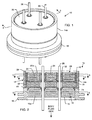
- FIGS. 1 and 2 illustrate a preferred embodiment wherein a feedthrough terminal assembly has an interior magnetic shield 12 and an exterior magnetic shield 14.
- the interior magnetic shield 12 comprises a plate 12a or a set of plates 12a embedded in an insulator 16 disposed over a central aperture of a conductive support 18 of the assembly 10.
- the conductive support 18 may comprise a ferrule or a housing.
- the embedded plate(s) 12a are comprised of a ferro-magnetic material such as nickel or the like. There are a number of other suitable materials for the plate set 12 or 12a. This can include any material containing magnetic dipoles, such as various nano-materials and other compositions.
- the plate set has a mass density of at least .005 grams per cubic centimeter, a saturization magnetization of from about 1 to about 50,000 gauss, a coercive force of from about .005 to about 10,000 Orsteds, a relative magnetic permeability from about .5 to about 750,000 and can have average particle sizes varying over a wide range. This includes the entire range of nanoparticles which would generally have a particle size of less than 200 nanometers.
- nickel is representative of any ferro-magnetic material as having the properties as described above.
- the exterior magnetic shield 14 comprises a sleeve 14a that peripherally surrounds at least a portion of the ferrule 18 and/or a feedthrough capacitor 20 on the assembly 10.
- the exterior magnetic shield 14 may be comprised of a ferro-magnetic material such as nickel, nickel alloy, or the like.
- the exterior magnetic shield 14 may also comprise a cap 14b which completely encloses the feedthrough capacitor opposite the insulator as shown in FIGS. 8 and 9.
- the conductive sleeve 14a makes contact to the gold braze area 40 to provide a reliable oxide-free electrical connection to the ferrule 18.
- the capacitor 20 is disposed on an axial side of the insulator 16 and has first and second sets of electrode plates 22, 24 embedded within an insulative or dielectric body 20a.
- the second set of electrode plates 24 are conductively coupled via the exterior magnetic shield 14 to the ferrule 18 or a housing or ground plane associated with an active implantable medical device incorporating the feedthrough terminal assembly.
- a lead wire 26 extends through the insulator 16 and the feedthrough capacitor 20 in non-conductive relation with the ferrule 18 and conductively coupled to the first set of electrode plates 22 in the capacitor 20.
- FIGURES 3 and 4 depict cross-sections of the feedthrough capacitor 20 shown in FIG. 2 and illustrate the first and second sets of electrode plates 22, 24.
- FIG. 3 shows the second set of electrode plates 24 in non-conductive relation with the lead wires 26 and extending to the outer edge of the feedthrough capacitor 20 to facilitate the conductive coupling with the ferrule 18, housing or ground plane.
- FIG. 4 illustrates the first set of electrode plates 22 that are conductively coupled to the lead wires 26.
- FIG. 5 depicts a cross-section from the novel insulator 16 of FIG. 2 illustrating a ferrous plate 12a, such as nickel, embedded in the insulator 16.
- the embedded plate(s) 12a provide a high degree of shielding against magnetic fields for the surface mounted inductor slab 32 and associated feedthrough capacitor 20.
- the feedthrough capacitor 20 may be externally grounded, i.e., by means of an electrical connection between the second set of electrode plates 24, the outer diameter metallization 28 of the feedthrough capacitor 20 and the ferrule 18, housing or other ground plane.
- the feedthrough capacitor 20 may also be internally grounded by means of a grounded pin 30, i.e., a short pin that extends through the feedthrough capacitor 20 in conductive relation with the second set of electrode plates 24 and at least part way through the insulator 16 in conductive relation with embedded ground plates 48, as shown in FIGS. 12, 13 and 19.
- a feedthrough terminal assembly 10 of the present invention may include one or more lossy ferrite inductor(s) 32 with both resistive and inductive properties, which is installed in proximity or adjacent to the feedthrough terminal assembly 10 of an active implantable medical device.
- the lossy ferrite inductor(s) 32 can be combined with one or more feedthrough capacitor(s) 20, which is mounted to the feedthrough terminal assembly 10.
- At least one terminal pin or lead wire 26 extends through the lossy ferrite inductor 32 in non-conductive relation. As described above, the lead wire 26 extends through the capacitor 20 in conductive relation with the first set of electrode plates 22.
- An outer ferrule 18, housing or ground plane is mounted adjacent to the capacitor 20 in conductive relation with the second set of electrode plates 24.
- the lossy ferrite inductor 32 works to absorb EMI energy (convert to heat) and increase the impedance of the lead wire 26.
- the advantages of a lossy ferrite inductor 32 are described in copending U.S. Patent Application No. 11/097,999, filed March 31, 2005 , and U.S. Provisional Application No. 60/724,479, filed October 6, 2005 .
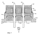
- FIGURE 7 is a cross-sectional drawing illustrating an alternate configuration for a "T" filter feedthrough terminal assembly 10 embodying the internal magnetic shield 12 (embedded conductive plates 12a) and external magnetic shield 14 (conductive sleeve 14a) of the present invention.
- This configuration is highly efficient in that the lossy ferrite inductor 32 is oriented toward the body fluid side of the feedthrough terminal assembly 10. Lossy ferrite inductor 32' points toward the electronics of the AIMD thereby tending to stabilize the device's input impedance.
- This configuration is a very high performance EMI filter that will offer broad attenuation throughout the frequency range from 1 MHz to 100 MHz and above.
- EMI filters using only a capacitance circuit device generally are only effective from 100 MHz to about 3 GHz.
- the configuration as shown in FIG. 7, has all the benefits of a feedthrough capacitor 20 with magnetic shields 12, 14, but with the added benefits of inductances and high frequency dissipative losses placed on both sides of the feedthrough capacitor 20.
- the performance of this configuration is not quite as high as the performance of other configurations, however, it is outstanding compared to all prior art devices incorporating only a feedthrough capacitor 20.
- the lossy ferrite inductor 32 is shielded by the surrounding ferro-magnetic material 14a and the embedded plate 12a.
- Said lossy ferrite inductor can be further shielded by the use of base metal electrode plates 22, 24 in capacitor 20. These would be typically nickel electrodes. Using a cardiac pacemaker as an example, this device would be integral to the housing of the cardiac pacemaker.
- the lossy ferrite inductor slab 32 When the patient was exposed to a medical procedure such as MRI, the lossy ferrite inductor slab 32 would be protected or shielded from the main static magnetic field of the MRI.
- the MRI might be 3 Teslas which produces a very powerful magnetizing force. In this case, the unshielded lossy ferrite inductor 32' would be mostly saturated. That is, its magnetic dipoles would line up with the static field of the MRI.
- lossy ferrite inductor 32 which is oriented towards the body fluid, would be protected from such saturation by the surrounding magnetic shielding materials as previously described. Accordingly, the "T" filter illustrated in FIG. 7 would continue to perform quite well in the presence of the main static field of the MRI. This is important in order to protect the interior electronics of the active implantable medical device from the MRI pulsed RF field. In the case of a 3 Tesla system, this pulsed RF field would operate at 128 MHz. Even though inductor 32' was mostly saturated, the remaining lossy ferrite slab inductor 32 with its associated feedthrough capacitor would still provide a very high degree of filter performance. In this case, when lossy ferrite slab inductor 32' is saturated, the filter would operate more like an "L" section filter.
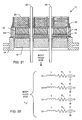
- FIG. 8 illustrates another alternate configuration for a feedthrough terminal assembly 10 embodying the internal magnetic shield 12 (embedded conductive plates 12a) and external magnetic shield 14 (conductive sleeve 14a) of the present invention.
- a first capacitor 20 is oriented toward the body fluid side.
- Inductor 32' is towards the AIMD electronic circuits.
- the first and second feedthrough capacitors 20, 20 ⁇ both have external metallization 34, 34' in order to conduct their respective ground electrode plates 24, 24' in parallel.
- the conductive fill medium 36 that connects the ground plates 24, 24' of the two capacitors 20, 20' makes contact to this metallization 34, 34'.
- Conductive fill medium 36 makes contact to gold braze area 38 to provide a reliable oxide-free electrical connection to the ferrule 18.
- the ferrule 18 is connected to the overall housing of the AIMD which acts as an electromagnetic shield.
- the ground electrode plates 24, 24' of both the lower and upper capacitors 20, 20 ⁇ become a part of the continuous overall electromagnetic shield of the active implantable medical device.
- This configuration is particularly effective in that it has a very high attenuation slope rate.
- it would be preferred in an MRI application to have the inductance point towards the body fluid side. The reason for this is that capacitor 20 tends to lower the input impedance of the AIMD. This causes a corresponding increase in MRI currents in the lead wires 26 on the body fluid side.
- the ferrule 18 of the feedthrough terminal assembly 10 has been extended upward so as to provide an annular space that surrounds the feedthrough capacitors 20 and 20'.
- the conductive material 36 is placed to make an electrical contact to both of the lower and upper capacitor 20, 20 ⁇ outside diameter ground termination areas 34, 34'.
- an exterior magnetic shield 14 which comprises a cap 14b is disposed over the feedthrough capacitor 20 and 20' and the portion of the ferrule 18 that has been extended upward. This cap 14b provides magnetic shielding similar to the interior magnetic shield 12 and conductive plates 12a described above. Referring to FIG.
- the exterior magnetic shield 14 in the form of the conductive cap 14b is shown separate from the feedthrough terminal assembly 10.
- the conductive cap 14b makes contact to gold braze area 40 to provide a reliable oxide free electrical connection to the ferrule 18.
- attachment to material 40 could be a nonconductive epoxy to simply seat the magnetic shield in place.
- lossy ferrite inductors 32 and 32' are now both shielded, for example, from the main static field of an MRI system.
- the feedthrough capacitors 20 and 20' are basically immune to the static field of the MRI. In other words, no magnetic shielding is really required for the feedthrough capacitors.
- the lossy ferrite inductors 32 and 32' operate through the presence of magnetic dipoles which present a resistive and inductive loss. They do this by opposing changes in current in the lead wires by interacting with the magnetic fields associated with said currents. Accordingly, it is a major improvement to prevent the saturation of these magnetic lossy elements 32 and 32' during the MRI procedure.
- LL circuit performance will be achieved providing a very high degree of attenuation for the MRI pulsed RF field.
- the patient when the patient is not undergoing a medical procedure such as MRI, the patient could be exposed to other environmental emitters, such as cellular telephones, microwave ovens and the like. In this case, a very high degree of filtering would be provided for the patient due to the effectivity of the "LL" filter circuit configuration.
- magnetic shielding elements it is not necessary to use all of the magnetic shielding elements at the same time as disclosed herein. For example, referring once again to FIG. 8, it may not be necessary to both provide the magnetic shield and its associated cap 14 and 14b along with magnetic shield plate set 12a. For example, one can eliminate magnetic shield set 12a. In this regard, there would only be a partial amount of magnetic shielding that was protecting the lossy ferrite slab 32 and 32' from saturating. However, as a cost tradeoff, sufficient filtering may still be provided. In other words, any of the individual elements as described in the present invention may be used either individually or in combination.
- FIGURE 10 illustrates the preferred embodiment of the configuration shown in FIG. 8 in that the lossy ferrite inductor 32 is now oriented toward the body fluid side lead wires 26.
- the lower capacitor 20 is a hybrid capacitor in that it has both external 34 and internal 42 metallization for connection to ground.
- the internal metallization 42 communicates with the ground through a conductive via hole.
- This via hole can contain a ground pin or be filled with a conductive material 36 such as a thermal setting conductive adhesive, a solder or the like.
- the important thing is that the ground hole of the hybrid capacitor 20 communicates with the ground plates and internal metallization 42' of the upper capacitor 20 ⁇ . It is in this way that the ground electrodes of capacitor 20' are connected to a ground plane.
- the via hole is filled with a conductive medium 36
- additional insulation 44 can be of the group of any insulating material including non-conductive polymers, non-conductive epoxies, insulating sleeves, insulating tubing and the like.
- the upper and lower feedthrough capacitors 20, 20' both have internal metallization 42, 42' in order to conduct the respective ground electrode plates in parallel.
- the conductive fill medium 36 that connects these two capacitors 20, 20' together makes contact to this metallization 42, 42'.
- the outside diameter metallization 34 of the lower feedthrough capacitor 20 provides a reliable electrical connection to gold braze area 40 to complete the external grounding.
- the hybrid capacitor 20 is attached to an elevated ferrule 18 flange with conductive bonding material 46.
- Gold sputter or braze or equivalent material 40 has been added to the top of the ferrule flange 18 so that a reliable oxide free electrical connection can be formed from the outside diameter metallization 34 (ground metallization) of feedthrough capacitor 20 to the ferrule 18 (see U.S. Patent Nos. 6,765,779 and 6,765,780 ).
- the feedthrough assembly 10 of FIG. 10 includes the optional interior magnetic shield 12 comprising one or more ferro-magnetic shield plates 12a embedded in the insulator 16 as well as the exterior magnetic shield 14 comprising the conductive sleeve 14a.
- the conductive plates 12a are electrically isolated in the insulator 16.
- the conductive sleeve 14a makes contact to the braze area 40 to provide a reliable oxide-free electrical connection to the ferrule 18.
- FIGURE 11 is the schematic diagram of the feedthrough terminal assembly 10 described in FIG. 10. It is desirable to have lossy ferrite inductor(s) 32 oriented towards the body fluid side. This has the effect of raising the impedance of the implanted lead wire 26 and electrically isolating the lower and upper feedthrough capacitors 20, 20 ⁇ . Also oriented toward the body fluid side is resistor R L1 . This is the high frequency lossy or ohmic electric characteristic of the lossy ferrite inductor 32. By orienting both the lossy ferrite inductor 32 and the resistor R L1 towards the body fluid side, this serves to raise the impedance of the lead wires 26. As previously mentioned, this is highly desirable to reduce the amount of MRI current flowing in the lead wires 26. Less current means less heating and less tendency to cause venous or TIP/RING ablation (tissue damage). Such overheating has been noted in the reference literature and is highly undesirable.
- the "L" filter feedthrough terminal assembly 10 comprises, generally, a plurality (in this case four) conductive lead wires 26 which extend through a conductive ferrule 18, in non-conductive relation, as will be more fully described herein.
- An insulator 16 (FIG. 13) supports each conductive lead wire 26 relative to the conductive ferrule 18 in electrically insulated relation.
- the insulator 16 is typically comprised of an alumina ceramic material, although it is not limited to such. However, the insulator 16 must be comprised of an electrically non-conductive material.
- the alumina insulator 16 includes at least one embedded monolithic ground plate 48 (see FIGS.
- the feedthrough terminal assembly 10 includes an external magnetic shield 14 comprising a conductive sleeve 14a.
- the internal magnetic shield 12 is omitted in favor of the ground plates 48 described previously.
- the embedded ground plates 48 will be both highly conductive and ferro-magnetic. An ideal material for this is nickel. In this case, embedded nickel plates will provide magnetic shielding from the main static field of MRI and also provide and very low impedance connection to ground for the capacitor grounding pin 30.
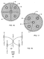
- the feedthrough terminal assembly 10 further includes an internally grounded feedthrough capacitor 20 that has first and second sets of electrode plates 22, 24 (FIGS. 13, 16 and 17). Passageways 50 are provided through the feedthrough capacitor 20 through which the lead wires 26 extend in conductive relation with the first set of electrode plates 22.
- the feedthrough capacitor 20 further includes a second passageway 52 into which a conductive ground pin 30 extends in conductive relation to the second set of electrode plates 24.
- the feedthrough terminal assembly 10 includes a monolithic, ceramic, internally grounded feedthrough capacitor 20 having two or more (in this instance five) passageways 50, 52 extending therethrough.
- Internally grounded electrodes are described by U. S. Patent Nos. 5,905,627 and 6,529,103 . Described herein is a novel method of providing a ground inside of the hermetic insulator for use in internally grounding the ground electrode plate set 24 of the capacitor 20.
- the outer four passageways 50 are configured to receive therethrough the respective conductive lead wires 26, and the internal diameter of the first passageways 50 are metallized (at 56) to form a conductive link between the first set of electrode plates 22 and the conductive lead wires 26.
- a conductive polyimide fill, solder, or the like 58 is placed within the first passageways 50 between the metallization 56 and the respective lead wire 26 to electrically link the lead wire 26 with the respective first set of electrode plates 22.
- both sets of electrode plates 22, 24 are typically silk-screened onto ceramic plates, forming the feedthrough capacitor 20. These plates 22, 24 are surrounded by an insulative ceramic material 20a that, for purposes of the present invention, need not be metallized on its exterior surfaces, as will be more fully discussed herein.
- the inner diameter of the central or second passageway 52 through the feedthrough capacitor 20 is also metallized (at 42) to conductively connect the second set of electrode plates 24, also referred to as the ground plates of the feedthrough capacitor 20.
- the second passageway 52 is configured to receive therethrough the conductive ground pin 30.
- a conductive polyimide, solder or other conductive fill 46 is placed within the second passageway 52 between the ground pin 30 and the metallization 42 to conductively couple the ground pin 30 to the second set of electrode plates 24.
- the second set of ground electrodes 24 extend to the outer periphery of the capacitor 20.
- the outer surface of the capacitor 20 is then metallized by metallization firing or plating operations, or otherwise providing external conductive connections between capacitor 20 and a ground, typically the conductive ferrule 84.
- metallization firing or plating operations or otherwise providing external conductive connections between capacitor 20 and a ground, typically the conductive ferrule 84.
- forming such conductive connections places a great deal of stress on the capacitor 20 during the manufacturing process and also presents drawbacks of the joining of materials which are not perfectly matched in thermal coefficient of expansion.
- the present invention eliminates the need for such external conductive connections between the capacitor 20 and the ferrule 18, or other ground.
- the conductive ferrule 18 is conductively mounted to a conductive substrate that may comprise, for example, the housing for an active implantable medical device.
- the ground pin 30, which is electrically and conductively coupled to the second set of electrode plates 24, as discussed above, extends into the insulator 16 so as to be conductively coupled with the one or more ground plates 48 of the insulator 16. More particularly, as illustrated in FIG. 13, the insulator 16 includes a passageway 60 adapted to receive the ground pin 30 therethrough.
- the ground plates 48 extend to the surface of this passageway 60, which is metallized (at 62) to conductively couple the ground plate 48 to one another.
- a conductive polyimide, solder, or other conductive fill 46 is placed within the passageway 60 to conductively couple the ground pin 30 to the ground plates 48.
- the ground plates 48 extend to the outer peripheral surface of the insulator 16, which includes a metallization 34 (FIG. 15).
- This metallization 34 can be formed by any means, including electroplating, thick film deposition, sputtering, or the like.
- the metallization 34 is conductively coupled to the ferrule 18, such as through the use of a conductive pre-form, solder, weld, braze or the like 64.
- the second set of electrode plates 24 of the feedthrough capacitor 20 are conductively coupled to the internal ground pin 30, which in turn is conductively coupled to the one or more ground plates 48 of the insulator 16, which are conductively coupled to the ferrule 18.
- the embedded ground electrode plates 48 can also be of ferrous material such as nickel so that both grounding of the internal ground pin 30, as well as, magnetic shielding of the lossy ferrite inductor 32 can be accomplished. Further shielding of the lossy ferrite inductor 32 is accomplished by the external magnetic cylindrical shield 14a.
- Passageways 54 are also formed through the insulator 16, in general alignment with the capacitor passageways 50, for passage of the lead wires 26 therethrough. Due to the non-conductive nature of the material comprising insulator 16, the lead wires 26 could pass through in a frictional fit manner. However, in a particularly preferred embodiment, an upper beveled portion of the passageway 54 is metallized 66 (see FIG. 15) such that a metal braze pre-form, such as gold or the like, 68 can securely and hermetically connect the lead wire 26 to the insulator 16. However, the metallization 66 does not come into contact with the one or more ground plates 48. Thus, the lead wires 26 are electrically isolated from the ground plates 48 and the ferrule 18.
- the capacitor 20 and insulator 16 are typically disposed relatively adjacent to one another and separated by a lossy ferrite inductor 32, as illustrated in FIG. 13.
- An insulative washer 70 is disposed between the inductor 32 and the capacitor 20 to provide a physical separation between them.
- Passageways 72 are formed in the inductor 32, as necessary, such that the lead wires 26 and ground pin 30 pass therethrough.
- the assembly 10 may incorporate one or more ferrite inductors 32 in various EMI filter circuit configurations as needed or desired.
- the electrical schematic for the configuration of the assembly 10 in FIGS. 12 and 13 is illustrated in FIG. 18.
- the ground pin 30 may extend well above the capacitor 20 surface if needed for convenient connection of an internal circuit or substrate to the ground (ferrule 18 or active implantable medical device housing). However, the ground pin 30 does not have to penetrate all the way through the insulator 16.
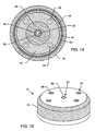
- FIGS. 19 and 20 another alternative configuration for a feedthrough terminal assembly 10 is illustrated.
- two ground pins 30 are utilized with their respective pair of feedthrough capacitors 20 and insulators 16 containing ground plates 48, as illustrated and described above.
- the pair of feedthrough capacitors 20 and insulators 16 are disposed on opposite sides of an intermediate inductor 32.
- the inductor 32, capacitors 20, and insulators 16 are separated by insulative washers 70 and 74.
- the electrical schematic for the assembly 10 shown in FIG. 19 is illustrated in FIG. 20.
- the feedthrough terminal assembly 10 possesses an exterior magnetic shield 14 comprising a ferro-magnetic sleeve 14a surrounding the ferrule 18.
- the interior magnetic shield 12 is omitted in favor of the preferably nickel ground plates 48.
- an "L" filter feedthrough terminal assembly 10 is illustrated.
- This is a quadpolar device as illustrated in the schematic diagram of FIG. 22.
- placing the lossy ferrite inductor 32 toward the body fluid side of the assembly 10 acts to increase the impedance on the lead wires 26.
- capacitor 20 By positioning capacitor 20 on the other side of the lossy ferrite inductor 32, its relatively low impedance is then positioned to protect the internal electronics of the device but not unduly lower the impedance of the implanted lead wires 26.
- This device includes an exterior magnetic shield 14 in the form of a conductive cap 14b which is inverted and placed around the lossy ferrite inductor 32.
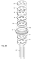
- FIG. 23 is an exploded perspective view of a feedthrough terminal assembly 10 of the present invention demonstrating the relationship of the feedthrough capacitor 20, the lossy ferrite inductor 32, the conductive cap 14b, the ferrule 18 including aperture 18a, the insulator 16, the lead wires 26, and the various insulative washers 70, 74.
- the inverted cap arrangement 14b, as illustrated in FIG. 21, is particularly desirable in the case where the overall housing of the active implantable medical device includes magnetic shielding.
- Such magnetic shields have been described in U. S. Patent Nos. 5,217,010 , 6,765,144 , 6,815,609 and the like.
- the presence of the inverted cap 14b provides additional shielding in the area where the lead wires 26 pass through the hermetic insulator 16. In this case, embedded electromagnetic shield plates 12a inside of the hermetic insulator 16 are not required.
Landscapes
- Engineering & Computer Science (AREA)
- Power Engineering (AREA)
- Manufacturing & Machinery (AREA)
- Microelectronics & Electronic Packaging (AREA)
- Health & Medical Sciences (AREA)
- Biomedical Technology (AREA)
- Nuclear Medicine, Radiotherapy & Molecular Imaging (AREA)
- Radiology & Medical Imaging (AREA)
- Life Sciences & Earth Sciences (AREA)
- Animal Behavior & Ethology (AREA)
- General Health & Medical Sciences (AREA)
- Public Health (AREA)
- Veterinary Medicine (AREA)
- Electrotherapy Devices (AREA)
- Magnetic Resonance Imaging Apparatus (AREA)
Applications Claiming Priority (4)
| Application Number | Priority Date | Filing Date | Title |
|---|---|---|---|
| US11/097,999 US7765005B2 (en) | 2004-02-12 | 2005-03-31 | Apparatus and process for reducing the susceptability of active implantable medical devices to medical procedures such as magnetic resonance imaging |
| US11/161,730 US7035076B1 (en) | 2005-08-15 | 2005-08-15 | Feedthrough filter capacitor assembly with internally grounded hermetic insulator |
| US72447905P | 2005-10-06 | 2005-10-06 | |
| US11/163,845 US7489495B2 (en) | 2004-04-15 | 2005-11-01 | Apparatus and process for reducing the susceptibility of active implantable medical devices to medical procedures such as magnetic resonance imaging |
Publications (2)
| Publication Number | Publication Date |
|---|---|
| EP1707237A2 true EP1707237A2 (fr) | 2006-10-04 |
| EP1707237A3 EP1707237A3 (fr) | 2007-04-18 |
Family
ID=36572427
Family Applications (1)
| Application Number | Title | Priority Date | Filing Date |
|---|---|---|---|
| EP06002818A Withdrawn EP1707237A3 (fr) | 2005-03-31 | 2006-02-13 | Dispositif et procédé pour la réduction de susceptibilité chez un dispositif médical implantable active aux procédés médicaux comme l'imagerie par résonance magnétique |
Country Status (2)
| Country | Link |
|---|---|
| US (1) | US7489495B2 (fr) |
| EP (1) | EP1707237A3 (fr) |
Families Citing this family (120)
| Publication number | Priority date | Publication date | Assignee | Title |
|---|---|---|---|---|
| US8244370B2 (en) | 2001-04-13 | 2012-08-14 | Greatbatch Ltd. | Band stop filter employing a capacitor and an inductor tank circuit to enhance MRI compatibility of active medical devices |
| US20080229590A1 (en) * | 2001-01-22 | 2008-09-25 | Robert Garrett | Roofmates shingle knife |
| US20070088416A1 (en) * | 2001-04-13 | 2007-04-19 | Surgi-Vision, Inc. | Mri compatible medical leads |
| WO2002083016A1 (fr) | 2001-04-13 | 2002-10-24 | Surgi-Vision, Inc. | Systemes et procedes d'interventions guidees par resonance magnetique |
| US8219208B2 (en) * | 2001-04-13 | 2012-07-10 | Greatbatch Ltd. | Frequency selective passive component networks for active implantable medical devices utilizing an energy dissipating surface |
| US9295828B2 (en) | 2001-04-13 | 2016-03-29 | Greatbatch Ltd. | Self-resonant inductor wound portion of an implantable lead for enhanced MRI compatibility of active implantable medical devices |
| US8660645B2 (en) | 2002-02-28 | 2014-02-25 | Greatbatch Ltd. | Electronic network components utilizing biocompatible conductive adhesives for direct body fluid exposure |
| US7553295B2 (en) | 2002-06-17 | 2009-06-30 | Iradimed Corporation | Liquid infusion apparatus |
| US7955357B2 (en) | 2004-07-02 | 2011-06-07 | Ellipse Technologies, Inc. | Expandable rod system to treat scoliosis and method of using the same |
| EP1786320B1 (fr) * | 2004-07-27 | 2016-09-14 | MRI Interventions, Inc. | Systemes irm possedant des catheters de distribution universels compatibles irm avec des sondes a antenne irm et systemes et procedes associes |
| JP4912304B2 (ja) | 2004-08-09 | 2012-04-11 | ザ ジョンズ ホプキンス ユニヴァーシティ | 埋め込み可能なmri適合刺激リード及びアンテナ並びに関連するシステム |
| EP1878091B1 (fr) * | 2005-05-04 | 2017-02-22 | Boston Scientific Neuromodulation Corporation | Fil electrique ameliore pour un dispositif electronique tel qu'un dispositif implantable |
| US8055351B2 (en) * | 2005-10-21 | 2011-11-08 | Boston Scientific Neuromodulation Corporation | MRI-safe high impedance lead systems |
| TWI407870B (zh) | 2006-04-25 | 2013-09-01 | 日本特殊陶業股份有限公司 | 配線基板之製造方法 |
| US7391601B1 (en) * | 2006-07-12 | 2008-06-24 | Pacesetter, Inc. | Feedthrough filter assembly |
| US7862502B2 (en) | 2006-10-20 | 2011-01-04 | Ellipse Technologies, Inc. | Method and apparatus for adjusting a gastrointestinal restriction device |
| US8761895B2 (en) * | 2008-03-20 | 2014-06-24 | Greatbatch Ltd. | RF activated AIMD telemetry transceiver |
| US7502217B2 (en) * | 2007-02-16 | 2009-03-10 | Medtronic, Inc. | Filtering capacitor feedthrough assembly |
| ES2615402T3 (es) | 2007-03-19 | 2017-06-06 | Boston Scientific Neuromodulation Corporation | Cables compatibles con IRM y RF |
| JP5568316B2 (ja) * | 2007-03-19 | 2014-08-06 | ボストン サイエンティフィック ニューロモデュレイション コーポレイション | Mri/rf適合リード線、および関連のリード線を操作、作製する方法 |
| US7917218B2 (en) * | 2007-03-21 | 2011-03-29 | Medtronic, Inc. | Filtering capacitor feedthrough assembly |
| US8105282B2 (en) | 2007-07-13 | 2012-01-31 | Iradimed Corporation | System and method for communication with an infusion device |
| US20090099440A1 (en) * | 2007-10-11 | 2009-04-16 | Ingmar Viohl | Reduction of rf induced tissue heating using discrete winding patterns |
| US20090099555A1 (en) * | 2007-10-11 | 2009-04-16 | Ingmar Viohl | Reduction of rf induced tissue heating using conductive surface pattern |
| US20090112263A1 (en) | 2007-10-30 | 2009-04-30 | Scott Pool | Skeletal manipulation system |
| US9233240B2 (en) | 2007-12-12 | 2016-01-12 | Pacesetter, Inc. | Systems and methods for determining inductance and capacitance values for use with LC filters within implantable medical device leads to reduce lead heating during MRI |
| US20090159709A1 (en) | 2007-12-24 | 2009-06-25 | Dynamics Inc. | Advanced dynamic credit cards |
| WO2009117069A2 (fr) * | 2008-03-17 | 2009-09-24 | Surgivision, Inc. | Dispositifs médicaux à faible profil comportant des axes d’entraînement internes coopérant avec des instruments d’introduction amovibles, et méthodes associées |
| US10080889B2 (en) | 2009-03-19 | 2018-09-25 | Greatbatch Ltd. | Low inductance and low resistance hermetically sealed filtered feedthrough for an AIMD |
| US11147977B2 (en) | 2008-03-20 | 2021-10-19 | Greatbatch Ltd. | MLCC filter on an aimd circuit board conductively connected to a ground pin attached to a hermetic feedthrough ferrule |
| CN102037528A (zh) | 2008-03-20 | 2011-04-27 | 格瑞巴奇有限公司 | 屏蔽三端子平通emi/消能滤波器 |
| US9463329B2 (en) | 2008-03-20 | 2016-10-11 | Greatbatch Ltd. | Shielded three-terminal flat-through EMI/energy dissipating filter with co-fired hermetically sealed feedthrough |
| US9108066B2 (en) | 2008-03-20 | 2015-08-18 | Greatbatch Ltd. | Low impedance oxide resistant grounded capacitor for an AIMD |
| US8483840B2 (en) * | 2008-03-20 | 2013-07-09 | Greatbatch Ltd. | Dual function tuned L-C input trap passive EMI filter component network for an active implantable medical device |
| US11202707B2 (en) | 2008-03-25 | 2021-12-21 | Nuvasive Specialized Orthopedics, Inc. | Adjustable implant system |
| US20090281592A1 (en) * | 2008-05-08 | 2009-11-12 | Pacesetter, Inc. | Shaft-mounted rf filtering elements for implantable medical device lead to reduce lead heating during mri |
| US8468664B2 (en) | 2008-05-22 | 2013-06-25 | Greatbatch Ltd. | Process for manufacturing EMI filters utilizing counter-bored capacitors to facilitate solder re-flow |
| US7538006B1 (en) | 2008-05-24 | 2009-05-26 | International Business Machines Corporation | Annular damascene vertical natural capacitor |
| US20100094305A1 (en) * | 2008-10-13 | 2010-04-15 | Arvin Chang | Spinal distraction system |
| US11241257B2 (en) | 2008-10-13 | 2022-02-08 | Nuvasive Specialized Orthopedics, Inc. | Spinal distraction system |
| US20100106227A1 (en) * | 2008-10-23 | 2010-04-29 | Pacesetter, Inc. | Systems and Methods for Disconnecting Electrodes of Leads of Implantable Medical Devices During an MRI to Reduce Lead Heating |
| US8301249B2 (en) * | 2008-10-23 | 2012-10-30 | Pacesetter, Inc. | Systems and methods for exploiting the tip or ring conductor of an implantable medical device lead during an MRI to reduce lead heating and the risks of MRI-induced stimulation |
| US20110015713A1 (en) * | 2008-10-23 | 2011-01-20 | Pacesetter, Inc. | Systems and methods for reducing lead heating and the risks of mri-induced stimulation |
| US8382756B2 (en) | 2008-11-10 | 2013-02-26 | Ellipse Technologies, Inc. | External adjustment device for distraction device |
| US20100138192A1 (en) * | 2008-12-01 | 2010-06-03 | Pacesetter, Inc. | Systems and Methods for Selecting Components for Use in RF Filters Within Implantable Medical Device Leads Based on Inductance, Parasitic Capacitance and Parasitic Resistance |
| EP2376183B1 (fr) * | 2009-01-12 | 2021-07-07 | Greatbatch Ltd. | Système équilibré d'énergie accordée destiné à minimiser le chauffage de fils implantés dans un environnement de champ électromagnétique à haute puissance |
| US8197490B2 (en) | 2009-02-23 | 2012-06-12 | Ellipse Technologies, Inc. | Non-invasive adjustable distraction system |
| US8095224B2 (en) | 2009-03-19 | 2012-01-10 | Greatbatch Ltd. | EMI shielded conduit assembly for an active implantable medical device |
| US9622792B2 (en) | 2009-04-29 | 2017-04-18 | Nuvasive Specialized Orthopedics, Inc. | Interspinous process device and method |
| KR101792472B1 (ko) | 2009-09-04 | 2017-10-31 | 누베이시브 스페셜라이즈드 오소페딕스, 인크. | 뼈 성장 기구 및 방법 |
| US8886319B2 (en) * | 2009-11-12 | 2014-11-11 | Pacesetter, Inc. | MRI signal filtering for implantable medical device |
| FR2957749A1 (fr) * | 2010-03-22 | 2011-09-23 | Sorin Crm Sas | Procede de realisation d'une traversee electrique dans la paroi metallique d'un boitier, notamment de dispositif medical actif, et dispositif pourvu d'une telle traversee |
| US9248043B2 (en) | 2010-06-30 | 2016-02-02 | Ellipse Technologies, Inc. | External adjustment device for distraction device |
| US8734488B2 (en) | 2010-08-09 | 2014-05-27 | Ellipse Technologies, Inc. | Maintenance feature in magnetic implant |
| US9607764B2 (en) | 2010-10-20 | 2017-03-28 | Chun-Yen Chang | Method of fabricating high energy density and low leakage electronic devices |
| US9142354B2 (en) * | 2010-10-20 | 2015-09-22 | Chun-Yen Chang | High energy density and low leakage electronic devices |
| US8659870B2 (en) * | 2010-11-22 | 2014-02-25 | Greatbatch Ltd. | Modular EMI filtered terminal assembly for an active implantable medical device |
| WO2012112396A2 (fr) | 2011-02-14 | 2012-08-23 | Ellipse Technologies, Inc. | Dispositif et méthode de traitement d'os fracturés |
| US10350421B2 (en) | 2013-06-30 | 2019-07-16 | Greatbatch Ltd. | Metallurgically bonded gold pocket pad for grounding an EMI filter to a hermetic terminal for an active implantable medical device |
| US10272252B2 (en) | 2016-11-08 | 2019-04-30 | Greatbatch Ltd. | Hermetic terminal for an AIMD having a composite brazed conductive lead |
| US11198014B2 (en) | 2011-03-01 | 2021-12-14 | Greatbatch Ltd. | Hermetically sealed filtered feedthrough assembly having a capacitor with an oxide resistant electrical connection to an active implantable medical device housing |
| US9427596B2 (en) | 2013-01-16 | 2016-08-30 | Greatbatch Ltd. | Low impedance oxide resistant grounded capacitor for an AIMD |
| US10596369B2 (en) | 2011-03-01 | 2020-03-24 | Greatbatch Ltd. | Low equivalent series resistance RF filter for an active implantable medical device |
| US10272253B2 (en) | 2016-11-10 | 2019-04-30 | Greatbatch Ltd. | Hermetic terminal for an active implantable medical device with composite co-fired filled via and body fluid side brazed leadwire |
| US9931514B2 (en) | 2013-06-30 | 2018-04-03 | Greatbatch Ltd. | Low impedance oxide resistant grounded capacitor for an AIMD |
| US9504843B2 (en) | 2011-08-19 | 2016-11-29 | Greatbach Ltd. | Implantable cardioverter defibrillator designed for use in a magnetic resonance imaging environment |
| US20130046354A1 (en) | 2011-08-19 | 2013-02-21 | Greatbatch Ltd. | Implantable cardioverter defibrillator designed for use in a magnetic resonance imaging environment |
| US8593816B2 (en) | 2011-09-21 | 2013-11-26 | Medtronic, Inc. | Compact connector assembly for implantable medical device |
| US10743794B2 (en) | 2011-10-04 | 2020-08-18 | Nuvasive Specialized Orthopedics, Inc. | Devices and methods for non-invasive implant length sensing |
| US10016220B2 (en) | 2011-11-01 | 2018-07-10 | Nuvasive Specialized Orthopedics, Inc. | Adjustable magnetic devices and methods of using same |
| US10420949B2 (en) | 2012-01-16 | 2019-09-24 | Greatbatch Ltd. | Method of manufacturing a feedthrough insulator for an active implantable medical device incorporating a post conductive paste filled pressing step |
| EP3366348B1 (fr) | 2012-01-16 | 2023-08-23 | Greatbatch Ltd. | Traversée hermétique co-connectée filtrée emi, condensateur de traversée et ensemble de dérivation pour dispositif médical implantable actif |
| US20130338714A1 (en) | 2012-06-15 | 2013-12-19 | Arvin Chang | Magnetic implants with improved anatomical compatibility |
| US9093974B2 (en) | 2012-09-05 | 2015-07-28 | Avx Corporation | Electromagnetic interference filter for implanted electronics |
| US9044281B2 (en) | 2012-10-18 | 2015-06-02 | Ellipse Technologies, Inc. | Intramedullary implants for replacing lost bone |
| CA2889769A1 (fr) | 2012-10-29 | 2014-05-08 | Ellipse Technologies, Inc. | Dispositifs ajustables pour traiter l'arthrite du genou |
| USRE46699E1 (en) | 2013-01-16 | 2018-02-06 | Greatbatch Ltd. | Low impedance oxide resistant grounded capacitor for an AIMD |
| US9179938B2 (en) | 2013-03-08 | 2015-11-10 | Ellipse Technologies, Inc. | Distraction devices and method of assembling the same |
| US10226242B2 (en) | 2013-07-31 | 2019-03-12 | Nuvasive Specialized Orthopedics, Inc. | Noninvasively adjustable suture anchors |
| US9801734B1 (en) | 2013-08-09 | 2017-10-31 | Nuvasive, Inc. | Lordotic expandable interbody implant |
| EP2848281B1 (fr) * | 2013-09-16 | 2016-02-24 | BIOTRONIK SE & Co. KG | Dispositif d'électrodes pour un implant médical et implant médical doté d'un dispositif d'électrodes |
| US10751094B2 (en) | 2013-10-10 | 2020-08-25 | Nuvasive Specialized Orthopedics, Inc. | Adjustable spinal implant |
| AU2015253313B9 (en) | 2014-04-28 | 2020-09-10 | Nuvasive Specialized Orthopedics, Inc. | System for informational magnetic feedback in adjustable implants |
| CN107106209B (zh) | 2014-10-23 | 2020-07-14 | 诺威适骨科专科公司 | 骨骼生长装置和用于该骨骼生长装置的外部遥控 |
| US10136535B2 (en) * | 2014-12-24 | 2018-11-20 | Medtronic, Inc. | Hermetically-sealed packages including feedthrough assemblies |
| KR20230116081A (ko) | 2014-12-26 | 2023-08-03 | 누베이시브 스페셜라이즈드 오소페딕스, 인크. | 신연을 위한 시스템 및 방법 |
| WO2016134326A2 (fr) | 2015-02-19 | 2016-08-25 | Nuvasive, Inc. | Systèmes et procédés pour ajustement vertébral |
| US10363425B2 (en) | 2015-06-01 | 2019-07-30 | Avx Corporation | Discrete cofired feedthrough filter for medical implanted devices |
| BR112018007347A2 (pt) | 2015-10-16 | 2018-10-23 | Nuvasive Specialized Orthopedics, Inc. | dispositivos ajustáveis para o tratamento da artrite do joelho |
| AU2016368167B2 (en) | 2015-12-10 | 2021-04-22 | Nuvasive Specialized Orthopedics, Inc. | External adjustment device for distraction device |
| WO2017132646A1 (fr) | 2016-01-28 | 2017-08-03 | Nuvasive Specialized Orthopedics, Inc. | Systèmes de transport osseux |
| WO2017139548A1 (fr) | 2016-02-10 | 2017-08-17 | Nuvasive Specialized Orthopedics, Inc. | Systèmes et procédés de commande de variables chirurgicales multiples |
| US10449375B2 (en) | 2016-12-22 | 2019-10-22 | Greatbatch Ltd. | Hermetic terminal for an AIMD having a pin joint in a feedthrough capacitor or circuit board |
| US10249415B2 (en) | 2017-01-06 | 2019-04-02 | Greatbatch Ltd. | Process for manufacturing a leadless feedthrough for an active implantable medical device |
| EP3345652B1 (fr) | 2017-01-06 | 2020-12-09 | Greatbatch Ltd. | Procédé de fabrication d'une traversée pour dispositif médical implantable actif |
| EP3449973B1 (fr) | 2017-08-30 | 2022-12-21 | Greatbatch Ltd. | Ensemble de traversée pour un dispositif médical implantable actif |
| US10874865B2 (en) | 2017-11-06 | 2020-12-29 | Avx Corporation | EMI feedthrough filter terminal assembly containing a resin coating over a hermetically sealing material |
| US11268506B2 (en) | 2017-12-22 | 2022-03-08 | Iradimed Corporation | Fluid pumps for use in MRI environment |
| US10912945B2 (en) | 2018-03-22 | 2021-02-09 | Greatbatch Ltd. | Hermetic terminal for an active implantable medical device having a feedthrough capacitor partially overhanging a ferrule for high effective capacitance area |
| US10905888B2 (en) | 2018-03-22 | 2021-02-02 | Greatbatch Ltd. | Electrical connection for an AIMD EMI filter utilizing an anisotropic conductive layer |
| GB2574653B (en) * | 2018-06-14 | 2020-09-09 | Knowles (Uk) Ltd | Capacitor having an electrical termination |
| WO2020112271A1 (fr) | 2018-11-29 | 2020-06-04 | Verily Life Sciences Llc | Liaison électromécanique biocompatible pour une électronique à substrat céramique destinée à un implant biomédical |
| WO2020163792A1 (fr) | 2019-02-07 | 2020-08-13 | 171Nuvasive Specialized Orthopedics, Inc. | Communication ultrasonore dans des dispositifs médicaux |
| US11589901B2 (en) | 2019-02-08 | 2023-02-28 | Nuvasive Specialized Orthopedics, Inc. | External adjustment device |
| WO2021045946A1 (fr) | 2019-09-03 | 2021-03-11 | Nuvasive Specialized Orthopedics, Inc. | Rapport acoustique pour implants dynamiques |
| US12605192B2 (en) | 2020-07-15 | 2026-04-21 | Globus Medical, Inc. | Ultrasonic communication in adjustable implants |
| WO2022055678A1 (fr) | 2020-09-08 | 2022-03-17 | Nuvasive Specialized Orthopedics, Inc. | Module de commande à distance pour implants réglables |
| EP4297674A1 (fr) | 2021-02-23 | 2024-01-03 | NuVasive Specialized Orthopedics, Inc. | Implant réglable, système et procédés |
| US11737787B1 (en) | 2021-05-27 | 2023-08-29 | Nuvasive, Inc. | Bone elongating devices and methods of use |
| US12023073B2 (en) | 2021-08-03 | 2024-07-02 | Nuvasive Specialized Orthopedics, Inc. | Adjustable implant |
| CN114646907B (zh) * | 2021-12-24 | 2023-10-20 | 中铁二院工程集团有限责任公司 | 一种基于机器学习的轨道交通低频磁场现场测量方法 |
| US12094661B2 (en) * | 2022-01-25 | 2024-09-17 | Medtronic, Inc. | Feedthrough ferrule with beveled ledge |
| US12551240B2 (en) | 2022-06-13 | 2026-02-17 | Nuvasive Inc. | Distraction loss magnet on-off mechanism |
| US12458417B2 (en) | 2022-08-15 | 2025-11-04 | Nuvasive Specialized Orthopedics Inc. | Intermedullary lengthening implant with integrated load sensor |
| US12508058B2 (en) | 2022-10-07 | 2025-12-30 | Nuvasive Specialized Orthopedics, Inc. | Adjustable tether implant |
| US12558133B2 (en) | 2023-04-25 | 2026-02-24 | Nuvasive, Inc. | Flat plate mechanisms for bone lengthening |
| US12533164B2 (en) | 2023-05-03 | 2026-01-27 | Nuvasive Specialized Orthopedics, Inc. | Adjustable implant |
| US12502533B2 (en) | 2023-09-29 | 2025-12-23 | PGX Platinum Health LLC | Adhesive housing for cardiac device inhibitor |
| CN118512712B (zh) * | 2024-06-11 | 2025-07-04 | 苏州新云医疗设备有限公司 | 具有电磁屏蔽功能的植入式电刺激器 |
| CN120037609B (zh) * | 2025-02-20 | 2025-10-24 | 南京从景生物技术有限公司 | 环形辐射器及基于该环形辐射器的超短波治疗机 |
Citations (11)
| Publication number | Priority date | Publication date | Assignee | Title |
|---|---|---|---|---|
| US4424551A (en) | 1982-01-25 | 1984-01-03 | U.S. Capacitor Corporation | Highly-reliable feed through/filter capacitor and method for making same |
| US5217010A (en) | 1991-05-28 | 1993-06-08 | The Johns Hopkins University | Ecg amplifier and cardiac pacemaker for use during magnetic resonance imaging |
| US5333095A (en) | 1993-05-03 | 1994-07-26 | Maxwell Laboratories, Inc., Sierra Capacitor Filter Division | Feedthrough filter capacitor assembly for human implant |
| US5751539A (en) | 1996-04-30 | 1998-05-12 | Maxwell Laboratories, Inc. | EMI filter for human implantable heart defibrillators and pacemakers |
| US5905627A (en) | 1997-09-10 | 1999-05-18 | Maxwell Energy Products, Inc. | Internally grounded feedthrough filter capacitor |
| US5973906A (en) | 1998-03-17 | 1999-10-26 | Maxwell Energy Products, Inc. | Chip capacitors and chip capacitor electromagnetic interference filters |
| US6008980A (en) | 1997-11-13 | 1999-12-28 | Maxwell Energy Products, Inc. | Hermetically sealed EMI feedthrough filter capacitor for human implant and other applications |
| US6529103B1 (en) | 2000-09-07 | 2003-03-04 | Greatbatch-Sierra, Inc. | Internally grounded feedthrough filter capacitor with improved ground plane design for human implant and other applications |
| US6765779B2 (en) | 2002-02-28 | 2004-07-20 | Greatbatch-Sierra, Inc. | EMI feedthrough filter terminal assembly for human implant applications utilizing oxide resistant biostable conductive pads for reliable electrical attachments |
| US6765144B1 (en) | 2002-01-22 | 2004-07-20 | Nanoset, Llc | Magnetic resonance imaging coated assembly |
| US6815609B1 (en) | 2002-12-18 | 2004-11-09 | Nanoset, Llc | Nanomagnetic composition |
Family Cites Families (3)
| Publication number | Priority date | Publication date | Assignee | Title |
|---|---|---|---|---|
| US6275369B1 (en) * | 1997-11-13 | 2001-08-14 | Robert A. Stevenson | EMI filter feedthough terminal assembly having a capture flange to facilitate automated assembly |
| US6999818B2 (en) * | 2003-05-23 | 2006-02-14 | Greatbatch-Sierra, Inc. | Inductor capacitor EMI filter for human implant applications |
| US7765005B2 (en) | 2004-02-12 | 2010-07-27 | Greatbatch Ltd. | Apparatus and process for reducing the susceptability of active implantable medical devices to medical procedures such as magnetic resonance imaging |
-
2005
- 2005-11-01 US US11/163,845 patent/US7489495B2/en not_active Expired - Fee Related
-
2006
- 2006-02-13 EP EP06002818A patent/EP1707237A3/fr not_active Withdrawn
Patent Citations (14)
| Publication number | Priority date | Publication date | Assignee | Title |
|---|---|---|---|---|
| US4424551B1 (en) | 1982-01-25 | 1991-06-11 | Highly-reliable feed through/filter capacitor and method for making same | |
| US4424551A (en) | 1982-01-25 | 1984-01-03 | U.S. Capacitor Corporation | Highly-reliable feed through/filter capacitor and method for making same |
| US5217010A (en) | 1991-05-28 | 1993-06-08 | The Johns Hopkins University | Ecg amplifier and cardiac pacemaker for use during magnetic resonance imaging |
| US5333095A (en) | 1993-05-03 | 1994-07-26 | Maxwell Laboratories, Inc., Sierra Capacitor Filter Division | Feedthrough filter capacitor assembly for human implant |
| US5751539A (en) | 1996-04-30 | 1998-05-12 | Maxwell Laboratories, Inc. | EMI filter for human implantable heart defibrillators and pacemakers |
| US5905627A (en) | 1997-09-10 | 1999-05-18 | Maxwell Energy Products, Inc. | Internally grounded feedthrough filter capacitor |
| US6008980A (en) | 1997-11-13 | 1999-12-28 | Maxwell Energy Products, Inc. | Hermetically sealed EMI feedthrough filter capacitor for human implant and other applications |
| US5973906A (en) | 1998-03-17 | 1999-10-26 | Maxwell Energy Products, Inc. | Chip capacitors and chip capacitor electromagnetic interference filters |
| US6529103B1 (en) | 2000-09-07 | 2003-03-04 | Greatbatch-Sierra, Inc. | Internally grounded feedthrough filter capacitor with improved ground plane design for human implant and other applications |
| US6566978B2 (en) | 2000-09-07 | 2003-05-20 | Greatbatch-Sierra, Inc. | Feedthrough capacitor filter assemblies with leak detection vents |
| US6765144B1 (en) | 2002-01-22 | 2004-07-20 | Nanoset, Llc | Magnetic resonance imaging coated assembly |
| US6765779B2 (en) | 2002-02-28 | 2004-07-20 | Greatbatch-Sierra, Inc. | EMI feedthrough filter terminal assembly for human implant applications utilizing oxide resistant biostable conductive pads for reliable electrical attachments |
| US6765780B2 (en) | 2002-02-28 | 2004-07-20 | Greatbatch-Sierra, Inc. | EMI feedthrough filter terminal assembly having surface mounted, internally grounded hybrid capacitor |
| US6815609B1 (en) | 2002-12-18 | 2004-11-09 | Nanoset, Llc | Nanomagnetic composition |
Non-Patent Citations (4)
| Title |
|---|
| C. GABRIEL; S. GABRIEL; E. CORTOUT, DIELEC- TRIC PROPERTIES OF BIOLOGICAL TISSUES: I. LITERATURE SURVEY |
| ROGER CHRISTOPH LUCHINGER: "Safety Aspects of Cardiac Pacemakers in Magnetic Resonance Imaging", SWISS FEDERAL INSTITUTE OF TECHNOLOGY ZURICH |
| S. GABRIEL; R.W. LAU; C. GABRIEL, DIELECTRIC PROPERTIES OF BIOLOGICAL TISSUES: II. MEASURE- MENTS AND THE FREQUENCY RANGE 0 HZ TO 20 GHZ |
| S. GABRIEL; R.W. LAU; C. GABRIEL: "ADVANCED ENGINEERING ELECTROMAGNETICS", 1989, WILEY, article "Dielectric Properties of Biological Tissues: III. Parametric Models for the Diel" |
Also Published As
| Publication number | Publication date |
|---|---|
| EP1707237A3 (fr) | 2007-04-18 |
| US20060085043A1 (en) | 2006-04-20 |
| US7489495B2 (en) | 2009-02-10 |
Similar Documents
| Publication | Publication Date | Title |
|---|---|---|
| US7489495B2 (en) | Apparatus and process for reducing the susceptibility of active implantable medical devices to medical procedures such as magnetic resonance imaging | |
| US7765005B2 (en) | Apparatus and process for reducing the susceptability of active implantable medical devices to medical procedures such as magnetic resonance imaging | |
| US9248283B2 (en) | Band stop filter comprising an inductive component disposed in a lead wire in series with an electrode | |
| US8244370B2 (en) | Band stop filter employing a capacitor and an inductor tank circuit to enhance MRI compatibility of active medical devices | |
| US8977355B2 (en) | EMI filter employing a capacitor and an inductor tank circuit having optimum component values | |
| US9002471B2 (en) | Independently actuatable switch for selection of an MRI compatible bandstop filter placed in series with a particular therapy electrode of an active implantable medical device | |
| US10080889B2 (en) | Low inductance and low resistance hermetically sealed filtered feedthrough for an AIMD | |
| US9061139B2 (en) | Implantable lead with a band stop filter having a capacitor in parallel with an inductor embedded in a dielectric body | |
| US20090163980A1 (en) | Switch for turning off therapy delivery of an active implantable medical device during mri scans | |
| JP2009045425A (ja) | Mri適合性を高めるために能動医療装置のリードワイヤ又は回路と直列にガイドワイヤと共に配置するように適応可能なタンクフィルタ | |
| JP2009514617A (ja) | Mri適合性を高めるために能動医療装置のリードワイヤ又は回路と直列に配置されたタンクフィルタ | |
| CN102037528A (zh) | 屏蔽三端子平通emi/消能滤波器 | |
| CN101321553A (zh) | 与主动式医疗装置的引线或电路串联布置的用于提高mri兼容性的箱式滤波器 |
Legal Events
| Date | Code | Title | Description |
|---|---|---|---|
| PUAI | Public reference made under article 153(3) epc to a published international application that has entered the european phase |
Free format text: ORIGINAL CODE: 0009012 |
|
| AK | Designated contracting states |
Kind code of ref document: A2 Designated state(s): AT BE BG CH CY CZ DE DK EE ES FI FR GB GR HU IE IS IT LI LT LU LV MC NL PL PT RO SE SI SK TR |
|
| AX | Request for extension of the european patent |
Extension state: AL BA HR MK YU |
|
| PUAL | Search report despatched |
Free format text: ORIGINAL CODE: 0009013 |
|
| AK | Designated contracting states |
Kind code of ref document: A3 Designated state(s): AT BE BG CH CY CZ DE DK EE ES FI FR GB GR HU IE IS IT LI LT LU LV MC NL PL PT RO SE SI SK TR |
|
| AX | Request for extension of the european patent |
Extension state: AL BA HR MK YU |
|
| 17P | Request for examination filed |
Effective date: 20070511 |
|
| 17Q | First examination report despatched |
Effective date: 20070618 |
|
| AKX | Designation fees paid |
Designated state(s): AT BE BG CH CY CZ DE DK EE ES FI FR GB GR HU IE IS IT LI LT LU LV MC NL PL PT RO SE SI SK TR |
|
| STAA | Information on the status of an ep patent application or granted ep patent |
Free format text: STATUS: THE APPLICATION IS DEEMED TO BE WITHDRAWN |
|
| 18D | Application deemed to be withdrawn |
Effective date: 20071030 |