EP1707816B2 - Vakuumpumpe - Google Patents
Vakuumpumpe Download PDFInfo
- Publication number
- EP1707816B2 EP1707816B2 EP06400014.4A EP06400014A EP1707816B2 EP 1707816 B2 EP1707816 B2 EP 1707816B2 EP 06400014 A EP06400014 A EP 06400014A EP 1707816 B2 EP1707816 B2 EP 1707816B2
- Authority
- EP
- European Patent Office
- Prior art keywords
- vane
- vacuum pump
- rotor
- circumferential surface
- wing
- Prior art date
- Legal status (The legal status is an assumption and is not a legal conclusion. Google has not performed a legal analysis and makes no representation as to the accuracy of the status listed.)
- Expired - Lifetime
Links
Images

Classifications
-
- F—MECHANICAL ENGINEERING; LIGHTING; HEATING; WEAPONS; BLASTING
- F01—MACHINES OR ENGINES IN GENERAL; ENGINE PLANTS IN GENERAL; STEAM ENGINES
- F01C—ROTARY-PISTON OR OSCILLATING-PISTON MACHINES OR ENGINES
- F01C21/00—Component parts, details or accessories not provided for in groups F01C1/00 - F01C20/00
- F01C21/08—Rotary pistons
- F01C21/0809—Construction of vanes or vane holders
-
- F—MECHANICAL ENGINEERING; LIGHTING; HEATING; WEAPONS; BLASTING
- F04—POSITIVE - DISPLACEMENT MACHINES FOR LIQUIDS; PUMPS FOR LIQUIDS OR ELASTIC FLUIDS
- F04C—ROTARY-PISTON, OR OSCILLATING-PISTON, POSITIVE-DISPLACEMENT MACHINES FOR LIQUIDS; ROTARY-PISTON, OR OSCILLATING-PISTON, POSITIVE-DISPLACEMENT PUMPS
- F04C18/00—Rotary-piston pumps specially adapted for elastic fluids
- F04C18/30—Rotary-piston pumps specially adapted for elastic fluids having the characteristics covered by two or more of groups F04C18/02, F04C18/08, F04C18/22, F04C18/24, F04C18/48, or having the characteristics covered by one of these groups together with some other type of movement between co-operating members
- F04C18/34—Rotary-piston pumps specially adapted for elastic fluids having the characteristics covered by two or more of groups F04C18/02, F04C18/08, F04C18/22, F04C18/24, F04C18/48, or having the characteristics covered by one of these groups together with some other type of movement between co-operating members having the movement defined in group F04C18/08 or F04C18/22 and relative reciprocation between the co-operating members
- F04C18/344—Rotary-piston pumps specially adapted for elastic fluids having the characteristics covered by two or more of groups F04C18/02, F04C18/08, F04C18/22, F04C18/24, F04C18/48, or having the characteristics covered by one of these groups together with some other type of movement between co-operating members having the movement defined in group F04C18/08 or F04C18/22 and relative reciprocation between the co-operating members with vanes reciprocating with respect to the inner member
- F04C18/3441—Rotary-piston pumps specially adapted for elastic fluids having the characteristics covered by two or more of groups F04C18/02, F04C18/08, F04C18/22, F04C18/24, F04C18/48, or having the characteristics covered by one of these groups together with some other type of movement between co-operating members having the movement defined in group F04C18/08 or F04C18/22 and relative reciprocation between the co-operating members with vanes reciprocating with respect to the inner member the inner and outer member being in contact along one line or continuous surface substantially parallel to the axis of rotation
-
- F—MECHANICAL ENGINEERING; LIGHTING; HEATING; WEAPONS; BLASTING
- F05—INDEXING SCHEMES RELATING TO ENGINES OR PUMPS IN VARIOUS SUBCLASSES OF CLASSES F01-F04
- F05C—INDEXING SCHEME RELATING TO MATERIALS, MATERIAL PROPERTIES OR MATERIAL CHARACTERISTICS FOR MACHINES, ENGINES OR PUMPS OTHER THAN NON-POSITIVE-DISPLACEMENT MACHINES OR ENGINES
- F05C2201/00—Metals
- F05C2201/02—Light metals
- F05C2201/021—Aluminium
-
- F—MECHANICAL ENGINEERING; LIGHTING; HEATING; WEAPONS; BLASTING
- F05—INDEXING SCHEMES RELATING TO ENGINES OR PUMPS IN VARIOUS SUBCLASSES OF CLASSES F01-F04
- F05C—INDEXING SCHEME RELATING TO MATERIALS, MATERIAL PROPERTIES OR MATERIAL CHARACTERISTICS FOR MACHINES, ENGINES OR PUMPS OTHER THAN NON-POSITIVE-DISPLACEMENT MACHINES OR ENGINES
- F05C2201/00—Metals
- F05C2201/04—Heavy metals
- F05C2201/0433—Iron group; Ferrous alloys, e.g. steel
- F05C2201/0448—Steel
- F05C2201/046—Stainless steel or inox, e.g. 18-8
-
- F—MECHANICAL ENGINEERING; LIGHTING; HEATING; WEAPONS; BLASTING
- F05—INDEXING SCHEMES RELATING TO ENGINES OR PUMPS IN VARIOUS SUBCLASSES OF CLASSES F01-F04
- F05C—INDEXING SCHEME RELATING TO MATERIALS, MATERIAL PROPERTIES OR MATERIAL CHARACTERISTICS FOR MACHINES, ENGINES OR PUMPS OTHER THAN NON-POSITIVE-DISPLACEMENT MACHINES OR ENGINES
- F05C2201/00—Metals
- F05C2201/04—Heavy metals
- F05C2201/0469—Other heavy metals
- F05C2201/0475—Copper or alloys thereof
- F05C2201/0478—Bronze (Cu/Sn alloy)
-
- F—MECHANICAL ENGINEERING; LIGHTING; HEATING; WEAPONS; BLASTING
- F05—INDEXING SCHEMES RELATING TO ENGINES OR PUMPS IN VARIOUS SUBCLASSES OF CLASSES F01-F04
- F05C—INDEXING SCHEME RELATING TO MATERIALS, MATERIAL PROPERTIES OR MATERIAL CHARACTERISTICS FOR MACHINES, ENGINES OR PUMPS OTHER THAN NON-POSITIVE-DISPLACEMENT MACHINES OR ENGINES
- F05C2251/00—Material properties
- F05C2251/02—Elasticity
-
- F—MECHANICAL ENGINEERING; LIGHTING; HEATING; WEAPONS; BLASTING
- F05—INDEXING SCHEMES RELATING TO ENGINES OR PUMPS IN VARIOUS SUBCLASSES OF CLASSES F01-F04
- F05C—INDEXING SCHEME RELATING TO MATERIALS, MATERIAL PROPERTIES OR MATERIAL CHARACTERISTICS FOR MACHINES, ENGINES OR PUMPS OTHER THAN NON-POSITIVE-DISPLACEMENT MACHINES OR ENGINES
- F05C2251/00—Material properties
- F05C2251/10—Hardness
Definitions
- the invention relates to a vacuum pump with a vane, a pump housing and a rotor rotatably mounted therein, wherein the vane has a constant length and is slidably mounted in the rotor and the vane tips protrude radially on both sides from the rotor and rest on the inner peripheral surface of the pump housing, whereby the Wing defines a suction space and a pressure space.
- a vacuum pump which has a pump housing in which a rotor is arranged.
- This rotor supports a wing which rests against the inner peripheral side of the housing.
- the wing is constructed in two parts so that it can take on different lengths. This ensures that the wing always rests on the inner circumferential surface and divides the pump chamber into a pressure chamber and a suction chamber.
- the wing tips are provided with inserts made of a hard material.
- the invention is based on the object of providing a vacuum pump in which wear is minimal.
- the housing of the vacuum pump is made of steel, which has the advantage that the housing can absorb high forces and is nevertheless easy to work with.
- the wing consists of a metal which is harder than the housing of the vacuum pump, in particular harder than the inner circumferential surface of the pump housing.
- the wing consists, for example, of titanium or a titanium alloy, steel, stainless steel, aluminum or brass.
- the inner circumferential surface of the pump chamber is preferably essentially circular-cylindrical.
- the vane then makes a sinusoidal reciprocating motion within the slot of the rotor.
- the distribution of forces or the load changes at the tip of the wing are then continuous and not abrupt.
- recesses or openings are provided parallel to the wing tip and that the wing is slightly more elastic in its longitudinal direction due to the recesses or the openings.
- the wing can adapt to a pressure chamber that expands due to heat, so that the tightness is still guaranteed with both cold and warm vacuum pumps.
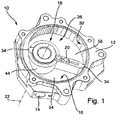
- the reference numeral 10 denotes a vacuum pump in which the housing 12 is shown without a housing cover.
- the housing 12 has a suction connection 14 which opens into an interior 16.
- a rotor designated as a whole by 18, in which a vane 20 is mounted so as to be displaceable orthogonally to the axis of rotation 22.
- the wing 20 has a constant length which is matched to the inner diameter of the housing 12.
- the rotor 18 extends through the housing 12, in particular a floor 26 of the interior space 18, and protrudes with a section not shown on the rear side of the housing 12, via which it is set in rotation (by means of a drive not shown).
- the interior 16 is delimited by an essentially circular cylindrical inner circumferential surface 32, on which the tips 34 of the wing 20 rest, which divide the interior into a suction chamber 54 and a pressure chamber 56, since the outer circumferential surface 44 of the rotor 18 is permanently in contact with the inner circumferential surface 32.
- the wing tips 34 have a flattened side 30 and a rounded side 36.
- the flattened side 30 is on the print side, which means that the in the Figure 1 illustrated wing 20 opposite to the direction rotates clockwise.
Landscapes
- Engineering & Computer Science (AREA)
- Mechanical Engineering (AREA)
- General Engineering & Computer Science (AREA)
- Rotary Pumps (AREA)
- Applications Or Details Of Rotary Compressors (AREA)
Description
- Die Erfindung betrifft eine Vakuumpumpe mit einem Flügel, einem Pumpengehäuse und einem darin drehbar gelagerten Rotor, wobei der Flügel eine konstante Länge aufweist und verschieblich im Rotor gelagert ist und die Flügelspitzen beidseitig aus dem Rotor radial herausragen und an der Innenumfangsfläche des Pumpengehäuses anliegen, wodurch der Flügel einen Saugraum und einen Druckraum definiert.
- Aus der
EP-A-1 471 255 ist eine Vakuumpumpe bekannt, welche ein Pumpengehäuse aufweist, in welchem ein Rotor angeordnet ist. Dieser Rotor lagert einen Flügel, welcher an der Innenumfangsseite des Gehäuses anliegt. Der Flügel ist zweiteilig aufgebaut, sodass er unterschiedliche Längen annehmen kann. Dadurch ist gewährleistet, dass der Flügel stets an der Innenumfangsfläche anliegt und den Pumpenraum in einen Druckraum und in einen Saugraum aufteilt. Außerdem sind die Flügelspitzen mit Einlagen versehen, welche aus einem harten Material bestehen. Es hat sich jedoch gezeigt, dass es zu zuweilen einem hohen Verschleiß am Flügel und an der Innenumfangsfläche kommt. - Aus der
EP-A-1 479 914 und derUS-A-4,133,617 sind Pumpen mit einem Flügel bekannt, bei dem die Flügelspitzen dreieckförmig ausgebildet sind. Bei derEP-A-1 424 495 werden die Flügelspitzen von Schuhen gebildet. DieUS-A-2,156,340 , dieJP-A-02 169 888 FR-A-512 155 - Der Erfindung liegt die Aufgabe zugrunde, eine Vakuumpumpe bereitzustellen, bei welcher der Verschleiß minimal ist.
- Diese Aufgabe wird mit einer Vakuumpumpe gelöst, die die Merkmale des Anspruchs 1 aufweist.
- Hierdurch werden optimale Andruckkräfte des Flügels an die Innenumfangswand erzielt.
- Bei einem bevorzugten Ausführungsbeispiel der Erfindung wird das Gehäuse der Vakuumpumpe aus Stahl hergestellt, was den Vorteil hat, dass das Gehäuse hohe Kräfte aufnehmen kann und dennoch einfach bearbeitbar ist. Der Flügel besteht aus einem Metall, welches härter ist, als das Gehäuse der Vakuumpumpe, insbesondere härter als die Innenumfangsfläche des Pumpengehäuses. Dabei besteht der Flügel zum Beispiel Titan oder einer Titanlegierung, Stahl, Edelstahl, Aluminium oder Messing.
- Mit Vorzug ist die Innenumfangsfläche des Pumpenraums im Wesentlichen kreiszylindrisch. Der Flügel vollzieht dann innerhalb des Schlitzes des Rotors eine sinusförmige Hin- und Herbewegung. Die Kräfteverteilung bzw. die Lastwechsel an der Spitze des Flügels sind dann kontinuierlich und nicht abrupt.
- Bei einer Weiterbildung ist vorgesehen, dass parallel zur Flügelspitze Ausnehmungen oder Durchbrüche vorgesehen sind und der Flügel aufgrund der Ausnehmungen oder der Durchbrüche in dessen Längsrichtung geringfügig elastischer ist. Hierdurch kann der Flügel einem sich wärmebedingt dehnenden Druckraum anpassen, sodass die Dichtigkeit sowohl bei kalten als auch bei warmen Vakuumpumpen nach wie vor gewährleistet ist.
- Weitere Vorteile, Merkmale und Einzelheiten der Erfindung ergeben sich aus den Unteransprüchen sowie der nachfolgenden Beschreibung, in der unter Bezugnahme auf die Zeichnung zwei besonders bevorzugte Ausführungsbeispiele im Einzelnen beschrieben sind. Dabei können die in der Zeichnung dargestellten und in der Beschreibung sowie in den Ansprüchen erwähnten Merkmale jeweils einzeln für sich oder in beliebiger Kombination erfindungswesentlich sein.
- In der Zeichnung zeigen:
- Figur 1
- eine perspektivische Ansicht eines ersten Ausführungsbeispiels einer Vakuumpumpe;
- Figur 2
- eine perspektivische Ansicht eines erstes Flügels; und
- Figur 3
- eine perspektivische Ansicht eines zweiten Ausführungsbeispiels eines Flügels.
- In der
Figur 1 ist mit dem Bezugszeichen 10 eine Vakuumpumpe bezeichnet, bei welcher das Gehäuse 12 ohne Gehäusedeckel dargestellt ist. Das Gehäuse 12 besitzt einen Sauganschluss 14, der in einen Innenraum 16 ausmündet. In diesem Innenraum 16 befindet sich ein insgesamt mit 18 bezeichneter Rotor, in welchem ein Flügel 20 orthogonal zur Drehachse 22 verschieblich gelagert ist. Der Flügel 20 besitzt eine konstante Länge, die auf den Innendurchmesser des Gehäuses 12 abgestimmt ist. Der Rotor 18 durchgreift das Gehäuse 12, insbesondere einen Boden 26 des Innenraums 18, und ragt mit einem nicht dargestellten Abschnitt auf der Rückseite aus dem Gehäuse 12 heraus, über welchen er (mittels eines nicht dargestellten Antriebs) in Drehung versetzt wird. Der Innenraum 16 ist von einer im Wesentlichen kreiszylindrischen Innenumfangsfläche 32 begrenzt, an welcher die Spitzen 34 des Flügels 20 anliegen, die den Innenraum in einen Saugraum 54 und einen Druckraum 56 unterteilen, da die Außenumfangsfläche 44 des Rotors 18 permanent an der Innenumfangsfläche 32 anliegt. - Sowohl zur Gewichtsreduzierung als auch zur Herstellung konstanter Wanddicken und ggfs. um den Flügel 20 in Längsrichtung geringfügig elastisch zu machen, weist dieser beim ersten Ausführungsbeispiel gemäß
Figur 2 dreieckförmige Durchbrüche 24 auf, die den Flügel 20 in Querrichtung durchsetzen. Beim zweiten Ausführungsbeispiel gemäßFigur 3 weist der Flügel 20 im Querschnitt längliche Durchbrüche 28 auf. - Außerdem ist in
Figur 2 erkennbar, dass die Flügelspitzen 34 eine abgeflachte Seite 30 und eine abgerundete Seite 36 aufweisen. Die abgeflachte Seite 30 befindet sich auf der Druckseite was bedeutet, dass der in derFigur 1 dargestellte Flügel 20 entgegen der Richtung des Uhrzeigersinns dreht.
Claims (5)
- Vakuumpumpe mit einem einzigen Flügel (20), einem Pumpengehäuse (12) und einem darin drehbar gelagerten Rotor (18), wobei der einzige Flügel (20) eine konstante Länge aufweist und in radialer Richtung verschieblich im Rotor (18) gelagert ist und die beiden Flügelspitzen (34) des einzigen Flügels (20) beidseitig aus dem Rotor (18) radial herausragen und an der Innenumfangsfläche (32) des Pumpengehäuses (12) anliegen, wobei der einzige Flügel (20) einteilig ausgebildet ist, aus Metall besteht und einen Saugraum (54) und einen Druckraum (56) definiert, wobei die Außenumfangsfläche (44) des Rotors (18) permanent an der Innenumfangsfläche (32) anliegt, dadurch gekennzeichnet, dass die Flügelspitzen (34) des einzigen Flügels (20) eine abgeflachte Seite (30) und eine abgerundete Seite (36) aufweisen, wobei die abgeflachte Seite (30) unter einem Winkel zur Längsachse des einzigen Flügels (20) steht und sich auf der Druckseite (56) befindet, und die abgerundete Seite (36) in den den Flügel (20) aufnehmenden Schlitz des Rotors (18) eintauchen kann.
- Vakuumpumpe nach Anspruch 1, dadurch gekennzeichnet, dass der Flügel (20) eine Härte besitzt, die größer ist als die der Innenumfangsfläche (32).
- Vakuumpumpe nach Anspruch 1 oder 2, dadurch gekennzeichnet, dass das Material des Flügels (20) aus Stahl, Edelstahl, Aluminium oder Messing ist.
- Vakuumpumpe nach einem der vorhergehenden Ansprüche, dadurch gekennzeichnet, dass die Innenumfangsfläche (32) im Wesentlichen kreiszylindrisch ist.
- Vakuumpumpe nach einem der vorhergehenden Ansprüche, dadurch gekennzeichnet, dass parallel zur Flügelspitze (34) Ausnehmungen oder Durchbrüche (24, 28) vorgesehen sind, und der Flügel (20) aufgrund dieser Ausnehmungen oder Durchbrüche (24, 28) in dessen Längsrichtung elastisch ist.
Applications Claiming Priority (1)
| Application Number | Priority Date | Filing Date | Title |
|---|---|---|---|
| DE102005015721A DE102005015721B3 (de) | 2005-03-31 | 2005-03-31 | Vakuumpumpe |
Publications (3)
| Publication Number | Publication Date |
|---|---|
| EP1707816A1 EP1707816A1 (de) | 2006-10-04 |
| EP1707816B1 EP1707816B1 (de) | 2014-04-30 |
| EP1707816B2 true EP1707816B2 (de) | 2021-05-19 |
Family
ID=36616794
Family Applications (1)
| Application Number | Title | Priority Date | Filing Date |
|---|---|---|---|
| EP06400014.4A Expired - Lifetime EP1707816B2 (de) | 2005-03-31 | 2006-03-17 | Vakuumpumpe |
Country Status (2)
| Country | Link |
|---|---|
| EP (1) | EP1707816B2 (de) |
| DE (1) | DE102005015721B3 (de) |
Families Citing this family (6)
| Publication number | Priority date | Publication date | Assignee | Title |
|---|---|---|---|---|
| WO2011154237A2 (de) * | 2010-06-09 | 2011-12-15 | Mahle International Gmbh | Drehschieberpumpe |
| DE102010026031A1 (de) * | 2010-07-03 | 2012-01-05 | Mahle International Gmbh | Drehschieberpumpe |
| DE102010026034A1 (de) * | 2010-07-03 | 2012-01-05 | Mahle International Gmbh | Drehschieberpumpe |
| DE102010026035A1 (de) * | 2010-07-03 | 2012-01-05 | Mahle International Gmbh | Drehschieberpumpe |
| DE102010026033A1 (de) * | 2010-07-03 | 2012-01-05 | Mahle International Gmbh | Drehschieberpumpe |
| DE102012002672B4 (de) | 2011-11-02 | 2014-07-24 | Dieter Voigt | Registerpumpe |
Family Cites Families (12)
| Publication number | Priority date | Publication date | Assignee | Title |
|---|---|---|---|---|
| FR512155A (fr) * | 1919-06-25 | 1921-01-17 | Parent Berthe | Pompe rotative |
| US2156340A (en) * | 1936-06-01 | 1939-05-02 | James P Johnson | Vacuum pump |
| US4133617A (en) * | 1976-01-27 | 1979-01-09 | Thomas Roach | Vane type pump with optional high rate of flow or high pressure characteristics |
| JPH02130289A (ja) * | 1988-11-09 | 1990-05-18 | Toyota Autom Loom Works Ltd | ベーン型圧縮機 |
| JPH02169888A (ja) * | 1988-12-21 | 1990-06-29 | Riken Corp | スルーベーン型回転式圧縮機用ベーン |
| DE4332540A1 (de) * | 1993-09-24 | 1995-03-30 | Bosch Gmbh Robert | Flügelzellenpumpe |
| KR19990072320A (ko) * | 1998-02-02 | 1999-09-27 | 나카무라 시게오 | 베인-타입유체기계 |
| DE50100666D1 (de) * | 2000-03-15 | 2003-10-30 | Joma Hydromechanic Gmbh | Verdrängerpumpe |
| US20040191104A1 (en) * | 2003-03-25 | 2004-09-30 | Wen-Shao Hsu | Rotary compressor having a rotor with a sliding vane |
| EP1471255B1 (de) * | 2003-04-24 | 2005-07-20 | Joma-Hydromechanic GmbH | Flügelzellenpumpe |
| DE102004064029B4 (de) * | 2004-07-09 | 2008-04-10 | Joma-Hydromechanic Gmbh | Einflügelvakuumpumpe |
| DE102004053521A1 (de) * | 2004-10-29 | 2006-05-11 | Joma-Hydromechanic Gmbh | Flügel für eine Rotorpumpe |
-
2005
- 2005-03-31 DE DE102005015721A patent/DE102005015721B3/de not_active Expired - Lifetime
-
2006
- 2006-03-17 EP EP06400014.4A patent/EP1707816B2/de not_active Expired - Lifetime
Also Published As
| Publication number | Publication date |
|---|---|
| EP1707816A1 (de) | 2006-10-04 |
| EP1707816B1 (de) | 2014-04-30 |
| DE102005015721B3 (de) | 2006-12-21 |
Similar Documents
| Publication | Publication Date | Title |
|---|---|---|
| DE102015219374B4 (de) | Verfahren zum Einbringen einer Wuchtmarke in das Verdichterrad eines Abgasturboladers und Abgasturbolader mit einem eine Wuchtmarke aufweisenden Verdichterrad | |
| EP1707816B2 (de) | Vakuumpumpe | |
| EP1766237B1 (de) | Einflügelvakuumpumpe | |
| DE1653921C3 (de) | Rotationskolbenpumpe | |
| DE2634318A1 (de) | Pumpe, vorzugsweise zum dosieren und kalibrieren | |
| DE1453435C3 (de) | Hydraulische Radialkolbenmaschine | |
| EP4076931B1 (de) | Ausgestaltung eines kreppschabers | |
| EP1805396B1 (de) | Rotorpumpe mit einem Flügel | |
| EP1954918A1 (de) | Vakuumpumpe | |
| DE3041477C2 (de) | Kolben und H-förmige Kolbenschuhe in Radialkolbenaggregaten | |
| DE522341C (de) | Drehkolben-Pumpe mit sichelfoermigem Arbeitsraum und in der Kolbentrommel verschiebbaren Kolben mit radialen Rippen, die Beanspruchungen der Kolben aufnehmen | |
| EP2466119A1 (de) | Kolben für Radialkolbenmaschine | |
| EP1948936A1 (de) | Vakuumpumpe | |
| CH636539A5 (de) | Stroemungsvibrator mit in einem gehaeuse rotierendem schwingkoerper. | |
| WO2007054163A1 (de) | Vakuumpumpe | |
| EP1934480B1 (de) | Rotorpumpe und flügel für eine rotorpumpe | |
| EP0064563B1 (de) | Kolbenschuhanordnung in einer Radialkolbenmaschine | |
| DE102022116195A1 (de) | Orbitalkolbenverdichter mit gebauter Exzenterwelle und Lagerung an Exzenterstück | |
| DE102006011913A1 (de) | Vakuumpumpe | |
| CH315985A (de) | Umlaufverdichter mit schraubenförmig verzahnten Rotoren | |
| CH674121A5 (en) | Vane-type pump - for sausage meat made of non-rusting or plastic components | |
| DE102006016240A1 (de) | Rotorpumpe und Flügel für eine Rotorpumpe | |
| DE113578C (de) | ||
| DE2458385C3 (de) | Hydrostatische Radialkolbenmaschine | |
| DE1553221C (de) | Drehkolbenpumpe |
Legal Events
| Date | Code | Title | Description |
|---|---|---|---|
| PUAI | Public reference made under article 153(3) epc to a published international application that has entered the european phase |
Free format text: ORIGINAL CODE: 0009012 |
|
| AK | Designated contracting states |
Kind code of ref document: A1 Designated state(s): AT BE BG CH CY CZ DE DK EE ES FI FR GB GR HU IE IS IT LI LT LU LV MC NL PL PT RO SE SI SK TR |
|
| AX | Request for extension of the european patent |
Extension state: AL BA HR MK YU |
|
| 17P | Request for examination filed |
Effective date: 20061114 |
|
| 17Q | First examination report despatched |
Effective date: 20061218 |
|
| AKX | Designation fees paid |
Designated state(s): DE FR GB |
|
| RAP1 | Party data changed (applicant data changed or rights of an application transferred) |
Owner name: JOMA-POLYTEC KUNSTSTOFFTECHNIK GMBH |
|
| RAP1 | Party data changed (applicant data changed or rights of an application transferred) |
Owner name: JOMA-POLYTEC GMBH |
|
| GRAP | Despatch of communication of intention to grant a patent |
Free format text: ORIGINAL CODE: EPIDOSNIGR1 |
|
| INTG | Intention to grant announced |
Effective date: 20131218 |
|
| GRAS | Grant fee paid |
Free format text: ORIGINAL CODE: EPIDOSNIGR3 |
|
| GRAA | (expected) grant |
Free format text: ORIGINAL CODE: 0009210 |
|
| AK | Designated contracting states |
Kind code of ref document: B1 Designated state(s): DE FR GB |
|
| REG | Reference to a national code |
Ref country code: GB Ref legal event code: FG4D Free format text: NOT ENGLISH |
|
| REG | Reference to a national code |
Ref country code: DE Ref legal event code: R096 Ref document number: 502006013694 Country of ref document: DE Effective date: 20140612 |
|
| REG | Reference to a national code |
Ref country code: DE Ref legal event code: R026 Ref document number: 502006013694 Country of ref document: DE |
|
| PLBI | Opposition filed |
Free format text: ORIGINAL CODE: 0009260 |
|
| 26 | Opposition filed |
Opponent name: WABCO GMBH Effective date: 20150129 |
|
| PLAX | Notice of opposition and request to file observation + time limit sent |
Free format text: ORIGINAL CODE: EPIDOSNOBS2 |
|
| REG | Reference to a national code |
Ref country code: DE Ref legal event code: R026 Ref document number: 502006013694 Country of ref document: DE Effective date: 20150129 |
|
| PLBB | Reply of patent proprietor to notice(s) of opposition received |
Free format text: ORIGINAL CODE: EPIDOSNOBS3 |
|
| GBPC | Gb: european patent ceased through non-payment of renewal fee |
Effective date: 20150317 |
|
| REG | Reference to a national code |
Ref country code: FR Ref legal event code: ST Effective date: 20151130 |
|
| PG25 | Lapsed in a contracting state [announced via postgrant information from national office to epo] |
Ref country code: GB Free format text: LAPSE BECAUSE OF NON-PAYMENT OF DUE FEES Effective date: 20150317 |
|
| PG25 | Lapsed in a contracting state [announced via postgrant information from national office to epo] |
Ref country code: FR Free format text: LAPSE BECAUSE OF NON-PAYMENT OF DUE FEES Effective date: 20150331 |
|
| APBM | Appeal reference recorded |
Free format text: ORIGINAL CODE: EPIDOSNREFNO |
|
| APBP | Date of receipt of notice of appeal recorded |
Free format text: ORIGINAL CODE: EPIDOSNNOA2O |
|
| APAH | Appeal reference modified |
Free format text: ORIGINAL CODE: EPIDOSCREFNO |
|
| APBQ | Date of receipt of statement of grounds of appeal recorded |
Free format text: ORIGINAL CODE: EPIDOSNNOA3O |
|
| APBU | Appeal procedure closed |
Free format text: ORIGINAL CODE: EPIDOSNNOA9O |
|
| PUAH | Patent maintained in amended form |
Free format text: ORIGINAL CODE: 0009272 |
|
| STAA | Information on the status of an ep patent application or granted ep patent |
Free format text: STATUS: PATENT MAINTAINED AS AMENDED |
|
| 27A | Patent maintained in amended form |
Effective date: 20210519 |
|
| AK | Designated contracting states |
Kind code of ref document: B2 Designated state(s): DE FR GB |
|
| REG | Reference to a national code |
Ref country code: DE Ref legal event code: R102 Ref document number: 502006013694 Country of ref document: DE |
|
| P01 | Opt-out of the competence of the unified patent court (upc) registered |
Effective date: 20230621 |
|
| PGFP | Annual fee paid to national office [announced via postgrant information from national office to epo] |
Ref country code: DE Payment date: 20250512 Year of fee payment: 20 |
|
| REG | Reference to a national code |
Ref country code: DE Ref legal event code: R071 Ref document number: 502006013694 Country of ref document: DE |