EP1707882A2 - Tôle de maintien d'une électrode - Google Patents
Tôle de maintien d'une électrode Download PDFInfo
- Publication number
- EP1707882A2 EP1707882A2 EP06111542A EP06111542A EP1707882A2 EP 1707882 A2 EP1707882 A2 EP 1707882A2 EP 06111542 A EP06111542 A EP 06111542A EP 06111542 A EP06111542 A EP 06111542A EP 1707882 A2 EP1707882 A2 EP 1707882A2
- Authority
- EP
- European Patent Office
- Prior art keywords
- seal
- electrode
- retaining plate
- electrode according
- holding plate
- Prior art date
- Legal status (The legal status is an assumption and is not a legal conclusion. Google has not performed a legal analysis and makes no representation as to the accuracy of the status listed.)
- Granted
Links
Images
Classifications
-
- F—MECHANICAL ENGINEERING; LIGHTING; HEATING; WEAPONS; BLASTING
- F23—COMBUSTION APPARATUS; COMBUSTION PROCESSES
- F23Q—IGNITION; EXTINGUISHING-DEVICES
- F23Q3/00—Igniters using electrically-produced sparks
- F23Q3/006—Details
-
- F—MECHANICAL ENGINEERING; LIGHTING; HEATING; WEAPONS; BLASTING
- F23—COMBUSTION APPARATUS; COMBUSTION PROCESSES
- F23Q—IGNITION; EXTINGUISHING-DEVICES
- F23Q9/00—Pilot flame igniters
- F23Q9/02—Pilot flame igniters without interlock with main fuel supply
- F23Q9/04—Pilot flame igniters without interlock with main fuel supply for upright burners, e.g. gas-cooker burners
- F23Q9/045—Structurally associated with a main-burner
Definitions
- the present invention relates to a holding plate for an electrode, e.g. an ignition electrode or monitoring electrode, consisting of a planar or more or less structured sheet metal section, with a spark plug receiving a receiving bore and fastening means and with a comprehensive at least the ignition electrode seal for a sealed attachment of the retaining plate to an opening for the ignition electrode having Wall.
- an electrode e.g. an ignition electrode or monitoring electrode, consisting of a planar or more or less structured sheet metal section, with a spark plug receiving a receiving bore and fastening means and with a comprehensive at least the ignition electrode seal for a sealed attachment of the retaining plate to an opening for the ignition electrode having Wall.
- Corresponding holding plates are required, for example, for electrodes which are installed in the wall of a gas boiler, wherein the ignition electrodes serve to bring it on ignition of a combustible gas to ignite. Monitoring electrodes signal the presence of the flame.
- the ignition electrodes are often sealed in the retaining plate attached, so that the retaining plate with the ignition electrode mounted therein is sealed.
- Such prefabricated parts which are provided from a holding plate equipped with a firing electrode, are generally purchased parts that get the manufacturer of gas boilers finished and mounted on their respective burners.
- the outer sides of the electrodes have corresponding electrical connection cables, which are connected to a corresponding power supply, which generates a voltage pulse as needed, which makes the ignition electrode generate a spark.
- corresponding retaining plates on two or more mounting holes which are located at a distance from the electrode. Now runs such a seal between the electrode and mounting hole too close to the mounting hole and then the retaining plate is fastened in the mounting hole by a very strong screw, the seal acts as a fulcrum and it can happen that the retaining plate on the side of the mounting hole is very strongly attracted to a housing wall, but for it on the side facing away from the mounting hole of the seal, namely where the ignition electrode is, from the boiler wall bulges.
- the seal must therefore be suitably arranged so that as possible no bulging takes place by appropriate leverage and the seal is largely clamped or compressed with a uniform pressure between the holding plate and the wall of the boiler.
- the present invention seeks to provide a corresponding retaining plate with seal, in which a secure seal is better ensured and possibly excessive pressing of the sealing material is avoided.
- This object is achieved in that the retaining plate is provided with an integrated seal.
- integral seal is understood to mean that the holding plate is prefabricated with the seal, ie that the seal is arranged in any correct position on the holding plate and at least fixed so far that it does not slip during assembly, so that it always maintains an optimum position, which ensures that the retaining plate is not deformed and bulged when attaching to the wall of a burner or boiler, that leaks occur.
- retaining plate is to be interpreted broadly and is intended to include all types of suitable, ie mechanically sufficiently stable, plate-shaped components, also made of plastic or ceramic.
- the seal according to the invention is integrated with the holding plate from the outset, i. is firmly and permanently arranged on the retaining plate, it can be ensured that the seal remains during assembly in the correct, appropriately selected position, so that a uniform contact pressure of the retaining plate is ensured at the seal.
- the seal may e.g. are applied over a large area on the side of the retaining plate facing a corresponding vessel wall and only leave out the fastening bores and the area of the ignition electrode and observe a certain small distance of a few (for example 2-8) millimeters from the outer edge as well as the fastening bores and the ignition electrode.
- the seal can also be applied in the form of a strand or a "bead" on the retaining plate, in particular sprayed or printed.
- silicone gaskets can readily be sprayed onto a metal in the form of a "caterpillar” and then adhere to the metal with a sufficient adhesive force so that such a gasket does not slip.
- the seal can also be injected / glued / imprinted into a groove.
- a single seal is provided which includes both the ignition electrode and the mounting holes.
- both the ignition electrode and the mounting holes are each surrounded by their own annular seals.
- the seals are provided in a circumferential groove, wherein the groove depth is significantly smaller than the thickness or height of the seal, measured perpendicular to the surface of the retaining plate.
- the groove depth is between 50 and 80% of the height or thickness of the seal.
- the groove-mounted seal on the open side of the groove protrudes well beyond the plane of the retaining plate and thus can be securely engaged with an opposite wall of a vessel or the like, the thickness of the seal being the dimensions the groove and the sealing material can be dimensioned so that the retaining plate can be tightened with his mounting screws until, for example, holding plate and wall of the housing have contact with each other, in which state the seal by a defined amount, namely exactly to the groove depth, compressed and thus experiences a uniform pressure force, which ensures a good seal.
- the defined compression of the sealing material can thus be predetermined and ensures secure sealing and long life of the seal.
- a seal that can not be sprayed, it can also be glued to the retaining plate or soldered when using a metallic seal.
- simple mechanical retaining means could be provided, e.g. small tabs or projections extending from the sheet and holding the gasket in place without compromising the sealing engagement between the gasket and the wall of a boiler or the like.
- a groove could have a depth that is slightly greater than half the diameter or thickness of the gasket, which gasket could be sized to lie against the groove wall with slight tension after insertion into the groove. Also in this way, the seal could be securely held in its desired position.
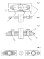
- a holding plate 1 in the form of a rectangular plate with two continuous mounting holes 3 and a central mounting hole in which a ignition electrode 4 is received sealed.
- FIG. 2 shows the retaining plate 1 with the mounting holes 3 and the ignition electrode 4 in longitudinal section, corresponding to a section along the line II-II in Figure 1.
- a circumferential seal 2 is discerned, which is arranged in a groove which is guided around the fastening bores 3 and the central bore with the ignition electrode 4 in an approximately elliptical shape.
- the cross section of the seal as an asymmetric trapezoid, which is arranged in a groove in the retaining plate and protrudes with a wedge-shaped in cross-section sealing lip of the groove.
- the seal 2 can either be inserted or glued into the groove with a certain bias or it can also be injected with a nozzle having a corresponding profile in the groove or applied for example by screen printing. In any case, the seal 2 is sufficiently fixed in the respective groove, so that they can be prefabricated as an integrated unit with the retaining plate 1, delivered and handled, in particular can be mounted.
- the retaining plate 1 as a whole has the shape of a simple rectangular plate, preferably of a metallic material, e.g. made of sheet steel.
- a corrosion-protected sheet which is either inherently corrosion-resistant or has a corresponding coating or surface treatment.
- a sheet you can of course use a corresponding plastic or ceramic part.
- the retaining plate can also have any other shape.
- FIG. 3 shows the retaining plate 1 in a state fastened by means of two fastening screws 6 to the wall 5 of a boiler or the like.
- the screws 6 are passed through the mounting holes 3 and screwed either in provided with a corresponding internal thread holes in the wall 5 or screwed with corresponding nuts from the inside of the wall, which are not shown here.
- an additional sealing washer may be inserted, although the firm engagement of a smooth screw head with the top of the sheet is generally sufficient to ensure sufficient tightness at this point, since it is only about larger leaks to prevent. If the threaded holes for the fastening screws 6 are executed in the wall of the boiler as a blind hole, the screws must not be self-sealed anyway.
- the provided in the housing wall 5 hole for receiving the ignition electrode 4 could be provided in the rest, moreover, easily with greater play to better compensate for tolerances in the arrangement of the various holes for the mounting screws and the ignition.
- FIG. 4 shows two further variants of the arrangement of seals.
- a hatched seal is sprayed over a large area on one side of the retaining plate 1 or imprinted for example by screen printing, with only the mounting holes 3 and the central bore for receiving the ignition electrode 4 are recessed.
- the outer edge regions of the rectangular retaining plate are not provided with the sealing layer.
- each of the existing in the retaining plate holes 3 for mounting screws and for the central ignition electrode 4 is surrounded by its own sealing ring. This also ensures that when tightening the corresponding mounting screws 6 all seals are pressed together with substantially the same contact pressure between the retaining plate 1 and the housing wall 5 and thereby seal securely.
- the seals 2 can, as shown in the example of Figures 1 to 3, are inserted into a groove or injected into this groove or glued, when using a metallic sealing material, they could also be soldered into the groove. However, they can also be sprayed on a smooth, flat surface of a retaining plate 1, which has no groove or glued, wherein during spraying, of course, only those sealing materials come into question, which also develop a sufficient adhesive force during the spraying to keep the seal 2 in its intended location during normal handling. In particular, in Figure 4a, the flat seal is only printed on the retaining plate, sprayed or glued.
- the sealing material can simultaneously serve for mutual alignment between the electrode and the burner.
- the sealing material is sprayed with a corresponding excess and fitted in the opposite groove. This results in a clean alignment and defined compression.
Landscapes
- Engineering & Computer Science (AREA)
- Chemical & Material Sciences (AREA)
- Combustion & Propulsion (AREA)
- Mechanical Engineering (AREA)
- General Engineering & Computer Science (AREA)
- Gasket Seals (AREA)
- Ignition Installations For Internal Combustion Engines (AREA)
- Connection Of Plates (AREA)
Priority Applications (2)
| Application Number | Priority Date | Filing Date | Title |
|---|---|---|---|
| PL06111542T PL1707882T3 (pl) | 2005-03-31 | 2006-03-22 | Płyta mocująca dla elektrody |
| SI200631953T SI1707882T1 (sl) | 2005-03-31 | 2006-03-22 | Držalna pločevina za elektrodo |
Applications Claiming Priority (1)
| Application Number | Priority Date | Filing Date | Title |
|---|---|---|---|
| DE200520005232 DE202005005232U1 (de) | 2005-03-31 | 2005-03-31 | Halteblech für Elektrode |
Publications (3)
| Publication Number | Publication Date |
|---|---|
| EP1707882A2 true EP1707882A2 (fr) | 2006-10-04 |
| EP1707882A3 EP1707882A3 (fr) | 2008-05-21 |
| EP1707882B1 EP1707882B1 (fr) | 2015-05-27 |
Family
ID=34673498
Family Applications (1)
| Application Number | Title | Priority Date | Filing Date |
|---|---|---|---|
| EP06111542.4A Expired - Lifetime EP1707882B1 (fr) | 2005-03-31 | 2006-03-22 | Tôle de maintien d'une électrode |
Country Status (7)
| Country | Link |
|---|---|
| EP (1) | EP1707882B1 (fr) |
| DE (1) | DE202005005232U1 (fr) |
| ES (1) | ES2544562T3 (fr) |
| HU (1) | HUE026119T2 (fr) |
| PL (1) | PL1707882T3 (fr) |
| PT (1) | PT1707882E (fr) |
| SI (1) | SI1707882T1 (fr) |
Cited By (1)
| Publication number | Priority date | Publication date | Assignee | Title |
|---|---|---|---|---|
| DE102010038004A1 (de) * | 2010-10-06 | 2012-04-12 | Prüfrex engineering e motion gmbh & co. kg | Direktaufstecksystem mit Dichtungskappe |
Families Citing this family (2)
| Publication number | Priority date | Publication date | Assignee | Title |
|---|---|---|---|---|
| AT515792B1 (de) * | 2014-07-28 | 2015-12-15 | Marco Gehrer | Kaminofen |
| CN106369632B (zh) * | 2016-10-28 | 2022-05-31 | 樱花卫厨(中国)股份有限公司 | 燃气热水器的高压点火装置及其固定方法 |
Citations (1)
| Publication number | Priority date | Publication date | Assignee | Title |
|---|---|---|---|---|
| DE3333698A1 (de) | 1983-09-17 | 1985-04-04 | Stiebel Eltron Gmbh & Co Kg, 3450 Holzminden | Befestigungseinrichtung eines elektrischen rohrheizkoerpers und verfahren zu deren herstellung |
Family Cites Families (3)
| Publication number | Priority date | Publication date | Assignee | Title |
|---|---|---|---|---|
| DE1980708U (de) * | 1967-11-25 | 1968-03-14 | Junkers & Co | Vorrichtung zum anzuenden und ueberwachen von gasbeheizten geraeten. |
| AT400483B (de) * | 1993-09-16 | 1996-01-25 | Vaillant Gmbh | Durchführung für eine elektrode, insbesondere durch die wand einer brennkammer |
| DE19749105A1 (de) * | 1997-11-06 | 1999-06-10 | Beru Ag | Stromdurchführungselement |
-
2005
- 2005-03-31 DE DE200520005232 patent/DE202005005232U1/de not_active Expired - Lifetime
-
2006
- 2006-03-22 HU HUE06111542A patent/HUE026119T2/en unknown
- 2006-03-22 PL PL06111542T patent/PL1707882T3/pl unknown
- 2006-03-22 PT PT61115424T patent/PT1707882E/pt unknown
- 2006-03-22 SI SI200631953T patent/SI1707882T1/sl unknown
- 2006-03-22 EP EP06111542.4A patent/EP1707882B1/fr not_active Expired - Lifetime
- 2006-03-22 ES ES06111542.4T patent/ES2544562T3/es not_active Expired - Lifetime
Patent Citations (1)
| Publication number | Priority date | Publication date | Assignee | Title |
|---|---|---|---|---|
| DE3333698A1 (de) | 1983-09-17 | 1985-04-04 | Stiebel Eltron Gmbh & Co Kg, 3450 Holzminden | Befestigungseinrichtung eines elektrischen rohrheizkoerpers und verfahren zu deren herstellung |
Cited By (2)
| Publication number | Priority date | Publication date | Assignee | Title |
|---|---|---|---|---|
| DE102010038004A1 (de) * | 2010-10-06 | 2012-04-12 | Prüfrex engineering e motion gmbh & co. kg | Direktaufstecksystem mit Dichtungskappe |
| DE102010038004B4 (de) * | 2010-10-06 | 2014-10-02 | Prüfrex engineering e motion gmbh & co. kg | Zündfunkengeber und Verfahren zu dessen Herstellung |
Also Published As
| Publication number | Publication date |
|---|---|
| DE202005005232U1 (de) | 2005-06-09 |
| EP1707882A3 (fr) | 2008-05-21 |
| PL1707882T3 (pl) | 2015-09-30 |
| ES2544562T3 (es) | 2015-09-01 |
| SI1707882T1 (sl) | 2015-09-30 |
| HUE026119T2 (en) | 2016-05-30 |
| EP1707882B1 (fr) | 2015-05-27 |
| PT1707882E (pt) | 2015-09-18 |
Similar Documents
| Publication | Publication Date | Title |
|---|---|---|
| DE102018211471B3 (de) | Batteriegehäuse | |
| DE4309088C2 (de) | Ortsfest einbaubare Scheibe für Kraftfahrzeuge | |
| EP1571305A1 (fr) | Dispositif de fixation d'un collecteur d'échappement à une culasse d'un moteur à combustion interne | |
| DE10257931B4 (de) | Dichtung | |
| EP1129286B1 (fr) | Soupape d'injection de carburant pour moteurs a combustion interne | |
| EP1601873B1 (fr) | Combinaison d'un joint plat avec une pompe à carburant haute pression. | |
| EP1482218B1 (fr) | Joint de culasse | |
| DE19511802A1 (de) | Klammerförmige Blechmutter mit Zentrierstreifen | |
| EP1429415A2 (fr) | Antenne à dispositif d'étanchéité surmoulé | |
| EP0354464A2 (fr) | Joint plat | |
| EP1707882B1 (fr) | Tôle de maintien d'une électrode | |
| DE2736097A1 (de) | Dichtungsvorrichtung fuer tueren eines koksofens | |
| EP3097303A1 (fr) | Raccord conique par vissage destiné à un conduit de combustible | |
| EP0930464B1 (fr) | Méthode et système d'assemblage étanche d'une électrode de brûleur | |
| DE19833302A1 (de) | Leitungsverbindung bei einer Einrichtung zur Abgasrückführung | |
| DE19642604C1 (de) | Gehäusedeckel mit Ausgleichselementen | |
| DE102008020099A1 (de) | Durch mindestens eine Befestigungsschraube zu montierendes Bauteil | |
| DE19750120C1 (de) | Rohrdichtschelle | |
| DE10044059C2 (de) | Verbindung von Beplankungsblechen mit Profilteilen von Profilstahlgerüsten | |
| DE19504405C2 (de) | Backofenleuchte | |
| EP0330126A2 (fr) | Joint de culasse | |
| DE102008058322B4 (de) | Verfahren und eine Dichtungsanordnung zum Abdichten einer einspringenden Ecke zwischen zwei Gehäuseteilen einer Brennkraftmaschine | |
| EP1024304B1 (fr) | Insert taraudé pour des pièces plastiques | |
| DE29619196U1 (de) | Vorrichtung zum Abdichten eines Ringraumes | |
| AT510601B1 (de) | Brennkraftmaschine mit zumindest einem durch eine zylinderbuchse gebildeten zylinder |
Legal Events
| Date | Code | Title | Description |
|---|---|---|---|
| PUAI | Public reference made under article 153(3) epc to a published international application that has entered the european phase |
Free format text: ORIGINAL CODE: 0009012 |
|
| AK | Designated contracting states |
Kind code of ref document: A2 Designated state(s): AT BE BG CH CY CZ DE DK EE ES FI FR GB GR HU IE IS IT LI LT LU LV MC NL PL PT RO SE SI SK TR |
|
| AX | Request for extension of the european patent |
Extension state: AL BA HR MK YU |
|
| PUAL | Search report despatched |
Free format text: ORIGINAL CODE: 0009013 |
|
| AK | Designated contracting states |
Kind code of ref document: A3 Designated state(s): AT BE BG CH CY CZ DE DK EE ES FI FR GB GR HU IE IS IT LI LT LU LV MC NL PL PT RO SE SI SK TR |
|
| AX | Request for extension of the european patent |
Extension state: AL BA HR MK YU |
|
| 17P | Request for examination filed |
Effective date: 20080723 |
|
| 17Q | First examination report despatched |
Effective date: 20080825 |
|
| AKX | Designation fees paid |
Designated state(s): AT BE BG CH CY CZ DE DK EE ES FI FR GB GR HU IE IS IT LI LT LU LV MC NL PL PT RO SE SI SK TR |
|
| RAP1 | Party data changed (applicant data changed or rights of an application transferred) |
Owner name: PAUL RAUSCHERT GMBH & CO. KG |
|
| GRAP | Despatch of communication of intention to grant a patent |
Free format text: ORIGINAL CODE: EPIDOSNIGR1 |
|
| INTG | Intention to grant announced |
Effective date: 20150108 |
|
| GRAS | Grant fee paid |
Free format text: ORIGINAL CODE: EPIDOSNIGR3 |
|
| GRAA | (expected) grant |
Free format text: ORIGINAL CODE: 0009210 |
|
| AK | Designated contracting states |
Kind code of ref document: B1 Designated state(s): AT BE BG CH CY CZ DE DK EE ES FI FR GB GR HU IE IS IT LI LT LU LV MC NL PL PT RO SE SI SK TR |
|
| REG | Reference to a national code |
Ref country code: GB Ref legal event code: FG4D Free format text: NOT ENGLISH |
|
| REG | Reference to a national code |
Ref country code: CH Ref legal event code: EP |
|
| REG | Reference to a national code |
Ref country code: AT Ref legal event code: REF Ref document number: 729072 Country of ref document: AT Kind code of ref document: T Effective date: 20150615 |
|
| REG | Reference to a national code |
Ref country code: IE Ref legal event code: FG4D Free format text: LANGUAGE OF EP DOCUMENT: GERMAN |
|
| REG | Reference to a national code |
Ref country code: RO Ref legal event code: EPE |
|
| REG | Reference to a national code |
Ref country code: DE Ref legal event code: R096 Ref document number: 502006014348 Country of ref document: DE |
|
| REG | Reference to a national code |
Ref country code: NL Ref legal event code: T3 |
|
| REG | Reference to a national code |
Ref country code: SE Ref legal event code: TRGR |
|
| REG | Reference to a national code |
Ref country code: ES Ref legal event code: FG2A Ref document number: 2544562 Country of ref document: ES Kind code of ref document: T3 Effective date: 20150901 |
|
| REG | Reference to a national code |
Ref country code: PT Ref legal event code: SC4A Free format text: AVAILABILITY OF NATIONAL TRANSLATION Effective date: 20150807 |
|
| REG | Reference to a national code |
Ref country code: PL Ref legal event code: T3 |
|
| REG | Reference to a national code |
Ref country code: LT Ref legal event code: MG4D |
|
| PG25 | Lapsed in a contracting state [announced via postgrant information from national office to epo] |
Ref country code: FI Free format text: LAPSE BECAUSE OF FAILURE TO SUBMIT A TRANSLATION OF THE DESCRIPTION OR TO PAY THE FEE WITHIN THE PRESCRIBED TIME-LIMIT Effective date: 20150527 Ref country code: LT Free format text: LAPSE BECAUSE OF FAILURE TO SUBMIT A TRANSLATION OF THE DESCRIPTION OR TO PAY THE FEE WITHIN THE PRESCRIBED TIME-LIMIT Effective date: 20150527 |
|
| PG25 | Lapsed in a contracting state [announced via postgrant information from national office to epo] |
Ref country code: LV Free format text: LAPSE BECAUSE OF FAILURE TO SUBMIT A TRANSLATION OF THE DESCRIPTION OR TO PAY THE FEE WITHIN THE PRESCRIBED TIME-LIMIT Effective date: 20150527 Ref country code: GR Free format text: LAPSE BECAUSE OF FAILURE TO SUBMIT A TRANSLATION OF THE DESCRIPTION OR TO PAY THE FEE WITHIN THE PRESCRIBED TIME-LIMIT Effective date: 20150828 Ref country code: IS Free format text: LAPSE BECAUSE OF FAILURE TO SUBMIT A TRANSLATION OF THE DESCRIPTION OR TO PAY THE FEE WITHIN THE PRESCRIBED TIME-LIMIT Effective date: 20150927 |
|
| REG | Reference to a national code |
Ref country code: SK Ref legal event code: T3 Ref document number: E 19161 Country of ref document: SK |
|
| PG25 | Lapsed in a contracting state [announced via postgrant information from national office to epo] |
Ref country code: EE Free format text: LAPSE BECAUSE OF FAILURE TO SUBMIT A TRANSLATION OF THE DESCRIPTION OR TO PAY THE FEE WITHIN THE PRESCRIBED TIME-LIMIT Effective date: 20150527 Ref country code: DK Free format text: LAPSE BECAUSE OF FAILURE TO SUBMIT A TRANSLATION OF THE DESCRIPTION OR TO PAY THE FEE WITHIN THE PRESCRIBED TIME-LIMIT Effective date: 20150527 |
|
| REG | Reference to a national code |
Ref country code: DE Ref legal event code: R097 Ref document number: 502006014348 Country of ref document: DE |
|
| REG | Reference to a national code |
Ref country code: FR Ref legal event code: PLFP Year of fee payment: 11 |
|
| PLBE | No opposition filed within time limit |
Free format text: ORIGINAL CODE: 0009261 |
|
| STAA | Information on the status of an ep patent application or granted ep patent |
Free format text: STATUS: NO OPPOSITION FILED WITHIN TIME LIMIT |
|
| 26N | No opposition filed |
Effective date: 20160301 |
|
| REG | Reference to a national code |
Ref country code: HU Ref legal event code: AG4A Ref document number: E026119 Country of ref document: HU |
|
| PG25 | Lapsed in a contracting state [announced via postgrant information from national office to epo] |
Ref country code: MC Free format text: LAPSE BECAUSE OF FAILURE TO SUBMIT A TRANSLATION OF THE DESCRIPTION OR TO PAY THE FEE WITHIN THE PRESCRIBED TIME-LIMIT Effective date: 20150527 Ref country code: LU Free format text: LAPSE BECAUSE OF FAILURE TO SUBMIT A TRANSLATION OF THE DESCRIPTION OR TO PAY THE FEE WITHIN THE PRESCRIBED TIME-LIMIT Effective date: 20160322 |
|
| REG | Reference to a national code |
Ref country code: CH Ref legal event code: PL |
|
| REG | Reference to a national code |
Ref country code: IE Ref legal event code: MM4A |
|
| PG25 | Lapsed in a contracting state [announced via postgrant information from national office to epo] |
Ref country code: LI Free format text: LAPSE BECAUSE OF NON-PAYMENT OF DUE FEES Effective date: 20160331 Ref country code: IE Free format text: LAPSE BECAUSE OF NON-PAYMENT OF DUE FEES Effective date: 20160322 Ref country code: CH Free format text: LAPSE BECAUSE OF NON-PAYMENT OF DUE FEES Effective date: 20160331 |
|
| REG | Reference to a national code |
Ref country code: FR Ref legal event code: PLFP Year of fee payment: 12 |
|
| REG | Reference to a national code |
Ref country code: FR Ref legal event code: PLFP Year of fee payment: 13 |
|
| PG25 | Lapsed in a contracting state [announced via postgrant information from national office to epo] |
Ref country code: CY Free format text: LAPSE BECAUSE OF FAILURE TO SUBMIT A TRANSLATION OF THE DESCRIPTION OR TO PAY THE FEE WITHIN THE PRESCRIBED TIME-LIMIT Effective date: 20150527 |
|
| PGFP | Annual fee paid to national office [announced via postgrant information from national office to epo] |
Ref country code: PT Payment date: 20210319 Year of fee payment: 16 |
|
| PGFP | Annual fee paid to national office [announced via postgrant information from national office to epo] |
Ref country code: SI Payment date: 20210316 Year of fee payment: 16 Ref country code: SE Payment date: 20210319 Year of fee payment: 16 Ref country code: BG Payment date: 20210323 Year of fee payment: 16 Ref country code: BE Payment date: 20210319 Year of fee payment: 16 Ref country code: AT Payment date: 20210322 Year of fee payment: 16 |
|
| PGFP | Annual fee paid to national office [announced via postgrant information from national office to epo] |
Ref country code: CZ Payment date: 20210322 Year of fee payment: 16 |
|
| PGFP | Annual fee paid to national office [announced via postgrant information from national office to epo] |
Ref country code: HU Payment date: 20210420 Year of fee payment: 16 Ref country code: ES Payment date: 20210521 Year of fee payment: 16 |
|
| PG25 | Lapsed in a contracting state [announced via postgrant information from national office to epo] |
Ref country code: PT Free format text: LAPSE BECAUSE OF NON-PAYMENT OF DUE FEES Effective date: 20220922 Ref country code: CZ Free format text: LAPSE BECAUSE OF NON-PAYMENT OF DUE FEES Effective date: 20220322 |
|
| REG | Reference to a national code |
Ref country code: AT Ref legal event code: MM01 Ref document number: 729072 Country of ref document: AT Kind code of ref document: T Effective date: 20220322 |
|
| REG | Reference to a national code |
Ref country code: BE Ref legal event code: MM Effective date: 20220331 |
|
| REG | Reference to a national code |
Ref country code: SI Ref legal event code: KO00 Effective date: 20221122 |
|
| PG25 | Lapsed in a contracting state [announced via postgrant information from national office to epo] |
Ref country code: SE Free format text: LAPSE BECAUSE OF NON-PAYMENT OF DUE FEES Effective date: 20220323 Ref country code: HU Free format text: LAPSE BECAUSE OF NON-PAYMENT OF DUE FEES Effective date: 20220323 Ref country code: AT Free format text: LAPSE BECAUSE OF NON-PAYMENT OF DUE FEES Effective date: 20220322 |
|
| PG25 | Lapsed in a contracting state [announced via postgrant information from national office to epo] |
Ref country code: SI Free format text: LAPSE BECAUSE OF NON-PAYMENT OF DUE FEES Effective date: 20220323 Ref country code: BE Free format text: LAPSE BECAUSE OF NON-PAYMENT OF DUE FEES Effective date: 20220331 |
|
| REG | Reference to a national code |
Ref country code: ES Ref legal event code: FD2A Effective date: 20230504 |
|
| PG25 | Lapsed in a contracting state [announced via postgrant information from national office to epo] |
Ref country code: ES Free format text: LAPSE BECAUSE OF NON-PAYMENT OF DUE FEES Effective date: 20220323 |
|
| PG25 | Lapsed in a contracting state [announced via postgrant information from national office to epo] |
Ref country code: BG Free format text: LAPSE BECAUSE OF NON-PAYMENT OF DUE FEES Effective date: 20220322 |
|
| PGFP | Annual fee paid to national office [announced via postgrant information from national office to epo] |
Ref country code: DE Payment date: 20250318 Year of fee payment: 20 |
|
| PGFP | Annual fee paid to national office [announced via postgrant information from national office to epo] |
Ref country code: NL Payment date: 20250319 Year of fee payment: 20 Ref country code: RO Payment date: 20250317 Year of fee payment: 20 |
|
| PGFP | Annual fee paid to national office [announced via postgrant information from national office to epo] |
Ref country code: FR Payment date: 20250325 Year of fee payment: 20 Ref country code: PL Payment date: 20250219 Year of fee payment: 20 |
|
| PGFP | Annual fee paid to national office [announced via postgrant information from national office to epo] |
Ref country code: IT Payment date: 20250325 Year of fee payment: 20 Ref country code: SK Payment date: 20250317 Year of fee payment: 20 Ref country code: GB Payment date: 20250321 Year of fee payment: 20 |
|
| PGFP | Annual fee paid to national office [announced via postgrant information from national office to epo] |
Ref country code: TR Payment date: 20250317 Year of fee payment: 20 |
|
| REG | Reference to a national code |
Ref country code: DE Ref legal event code: R071 Ref document number: 502006014348 Country of ref document: DE |
|
| REG | Reference to a national code |
Ref country code: NL Ref legal event code: MK Effective date: 20260321 |
|
| REG | Reference to a national code |
Ref country code: SK Ref legal event code: MK4A Ref document number: E 19161 Country of ref document: SK Expiry date: 20260322 Ref country code: GB Ref legal event code: PE20 Expiry date: 20260321 |
|
| PG25 | Lapsed in a contracting state [announced via postgrant information from national office to epo] |
Ref country code: SK Free format text: LAPSE BECAUSE OF EXPIRATION OF PROTECTION Effective date: 20260322 |