EP0330126A2 - Joint de culasse - Google Patents
Joint de culasse Download PDFInfo
- Publication number
- EP0330126A2 EP0330126A2 EP89102925A EP89102925A EP0330126A2 EP 0330126 A2 EP0330126 A2 EP 0330126A2 EP 89102925 A EP89102925 A EP 89102925A EP 89102925 A EP89102925 A EP 89102925A EP 0330126 A2 EP0330126 A2 EP 0330126A2
- Authority
- EP
- European Patent Office
- Prior art keywords
- cylinder head
- head gasket
- carrier
- sealing elements
- gasket according
- Prior art date
- Legal status (The legal status is an assumption and is not a legal conclusion. Google has not performed a legal analysis and makes no representation as to the accuracy of the status listed.)
- Withdrawn
Links
Images
Classifications
-
- F—MECHANICAL ENGINEERING; LIGHTING; HEATING; WEAPONS; BLASTING
- F02—COMBUSTION ENGINES; HOT-GAS OR COMBUSTION-PRODUCT ENGINE PLANTS
- F02F—CYLINDERS, PISTONS OR CASINGS, FOR COMBUSTION ENGINES; ARRANGEMENTS OF SEALINGS IN COMBUSTION ENGINES
- F02F11/00—Arrangements of sealings in combustion engines
- F02F11/002—Arrangements of sealings in combustion engines involving cylinder heads
-
- F—MECHANICAL ENGINEERING; LIGHTING; HEATING; WEAPONS; BLASTING
- F16—ENGINEERING ELEMENTS AND UNITS; GENERAL MEASURES FOR PRODUCING AND MAINTAINING EFFECTIVE FUNCTIONING OF MACHINES OR INSTALLATIONS; THERMAL INSULATION IN GENERAL
- F16J—PISTONS; CYLINDERS; SEALINGS
- F16J15/00—Sealings
- F16J15/02—Sealings between relatively-stationary surfaces
- F16J15/06—Sealings between relatively-stationary surfaces with solid packing compressed between sealing surfaces
- F16J15/10—Sealings between relatively-stationary surfaces with solid packing compressed between sealing surfaces with non-metallic packing
- F16J15/12—Sealings between relatively-stationary surfaces with solid packing compressed between sealing surfaces with non-metallic packing with metal reinforcement or covering
- F16J15/121—Sealings between relatively-stationary surfaces with solid packing compressed between sealing surfaces with non-metallic packing with metal reinforcement or covering with metal reinforcement
- F16J15/122—Sealings between relatively-stationary surfaces with solid packing compressed between sealing surfaces with non-metallic packing with metal reinforcement or covering with metal reinforcement generally parallel to the surfaces
- F16J15/123—Details relating to the edges of the packing
Definitions
- the invention relates to a cylinder head gasket according to the preamble of claim 1.
- the carrier consists of asbestos or a corresponding plastic.
- a flanged metal clip is provided as a sealing element.
- This cylinder head gasket is complex and expensive because of the flanging of the metal clips and their special shape.
- the carrier made of asbestos or plastic also shows setting behavior in the installed position. This means that the tightening torque of the screws can only be used to a limited extent.
- the screws on the cylinder head must be retightened after a certain time, due to the setting behavior of the materials used.
- this cylinder head gasket can no longer be reused after it has been removed because the carrier material bakes on the engine housing and / or the cylinder head after a correspondingly long period of use, so that the cylinder head gasket cannot be removed without damage.
- the invention has for its object to design the generic cylinder head gasket so that it ensures the setting of a precise, defined tightening torque when connecting the cylinder head to the engine housing with simple and inexpensive manufacture and can be used again after removal.
- the carrier consists of heat-resistant material, preferably of metal, which enables economical production.
- the sealing elements on the combustion chamber side do not have to be attached to the carrier in a complex flaring process; rather, the carrier itself is profiled to form the sealing elements on the combustion chamber side.
- a uniform, continuous heat distribution is possible in the carrier, so that no stresses occur when the cylinder head gasket according to the invention is used. This ensures an optimal seal.
- the carrier shows no setting behavior in the installed position, so that an exact tightening torque can be set when fastening the cylinder head to the engine housing.
- the sealing effect of the sealing elements can thus be optimally adjusted very easily.
- the cylinder head gasket can be easily dismantled because it does not stick to the cylinder head and / or the engine housing due to the carrier. It can therefore be easily removed and used again.
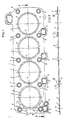
- the cylinder head gasket has a carrier 1, which consists of metallic material, such as stainless steel, copper-plated or galvanized steel, aluminum and the like.
- the recesses 2 are circular and each surrounded by a sealing element 4.
- the recesses 2 are provided for the cylinder chambers of a four-cylinder engine.
- In the carrier 1 further openings 5 and 6 for cooling channels are also arranged. They are each surrounded by further sealing elements 7 at a short distance.
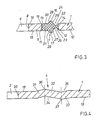
- the sealing element 7 will now be explained in more detail, which has the same design for the openings 5 and 6, respectively.
- the sealing element 7 runs parallel to the edge 8 of the opening 6 and connects a support section 9 containing the openings to the remaining part 10 of the support 1.
- the support 1 thus consists of separate parts, namely the support section 9 and the support part 10, which by the circumferential sealing element 7 are interconnected.
- the carrier section 9 is formed by an edge section of the opening 6 and is annular.
- the two carrier parts 9 and 10 can be mechanically connected to the sealing element 7.
- Sealing element 7 is chemically firmly connected to the carrier section 9 and the carrier part 10.
- the mutually facing, annular side surfaces 11 and 12 of the carrier section 9 and the carrier part 10 delimit an annular gap 13 which is essentially filled by the sealing element 7.
- the side surfaces 11, 12 also form binding surfaces to which the sealing element 7 is attached.
- the side surfaces 11, 12 are first preferably roughened for fastening the sealing element 7. A chemical adhesion promoter is then applied as a binder and the sealing element 7 is inserted and thus connected to the side surfaces 11 and 12.
- the cylinder head gasket is then subjected to a heat treatment, preferably vulcanization, so that an absolutely firm connection between the sealing element 7 and the carrier parts 9, 10 is achieved. This connection is so tight that the cylinder head gasket perfectly meets the requirements placed on it.
- the sealing element 7 in the connection area to the carrier section 9 has the same thickness as this, so that a firm connection between this carrier section and the sealing element 7 is ensured.
- the sealing element 7 is substantially thinner than the carrier part 10. This thinner edge 14 of the sealing element 7 is only about half as thick as the opposite edge 15 of the sealing element or as the carrier part 9.
- the sealing element 7 has two annular sealing lips 16 and 17, which protrude above the top and bottom 18 and 19 of the carrier 1.
- the two sealing lips 16, 17 are at the same height and each curve is continuously curved into the top and bottom 20 and 21 of the thicker edge 15 of the sealing element.
- the top 18 and bottom 19 of the support section 9 is in each case in a common plane with the top 20 and the bottom 21 of the edge 15 of the sealing element 7.
- the sealing element 7 is provided with a recess 22 and 23, the bottom of which 24 and 25 is curved in a partially circular cross-section and merges into a conical side wall 26 and 27 of the sealing lip 16 and 17, respectively.
- the opposite, also conical side wall 28 and 29 of the sealing lips 16 and 17 is continuously curved into the side walls 26, 27 and into the top and bottom 20 and 21 of the sealing element 7.
- the bottom 24, 25 of the depressions 22, 23 also merges into the side surface 12 of the carrier part 10 at a distance from the top and bottom 18, 19 of the carrier 1.
- the side walls 26 and 27 of the sealing lips 16, 17 are longer than the side walls 28 and 29, so that the bottom 24, 25 of the depressions 22, 23 lies within the cross-sectional thickness of the carrier 1.
- the sealing lips 16, 17 are compressed elastically.
- the material of the sealing lips 16, 17 is hereby displaced into the recesses 22, 23, so that the cylinder head gasket in the installed position has no parts protruding above the top and bottom 18, 19 and the sealing element 7 is not deformed to an unacceptably high degree.
- the sealing elements 7 can consist of elastomers, such as rubber, thermoplastic elastomers, plastics, soft metals and the like.
- the material of the sealing elements 7 depends on the desired area of application and the required sealing function. Since the two carrier parts 9 and 10 are connected to one another exclusively by the sealing element 7, that is to say there is no carrier web between these parts, a large space is available for the formation of the depressions 22, 23.
- the sealing element 17 is preferably symmetrical, but can also have an asymmetrical shape.
- the sealing element 7 can be designed differently on the top 18 of the carrier 1 than on the underside of the carrier.
- the depressions 22, 23 can be designed differently.
- the opposite side surfaces 11 and 12 of the carrier parts 9, 10, which limit the annular gap 13 for the sealing element 7, can be designed differently depending on the sealing and / or construction case.
- the side surfaces can be offset, have an irregular outline, be tooth-shaped or have a different profile.
- the sealing element 7 can be designed in any geometric configuration, depending on the desired technical requirements.
- the sealing element 7 consists of elastic material
- the carrier parts 9, 10 connected by this sealing element can move relative to one another.
- Such limited mobility is of great advantage in the case of thermal stresses on the parts to be sealed.
- the cylinder head gasket can adapt to the respective sealing conditions in the area of the openings 5, 6 without tension. Temperature fluctuations can also be compensated for by this relative mobility. It is given in all directions, that is, not only transversely to the top or bottom of the carrier 1, but also parallel to the carrier plane. A relative movement in an inclination plane is also possible.
- the sealing elements 7 are arranged in the region of the openings 5 and 6 provided for the cooling ducts of the internal combustion engine.
- the sealing elements 4 are in the area of the recesses 2 for the combustion chambers of the engine provided that consist of metallic material due to the high thermal stresses.
- the sealing elements 4 are explained in detail below with reference to FIG. 4.
- the sealing element 4 is formed by appropriate profiling of the carrier 1 itself.
- the sealing element 4 lies at a short distance from the edge 30 delimiting the recess 2. At a distance from this edge 30, the carrier 1 merges into a section 31 projecting over its upper side 18, which in cross section according to FIG. 4 merges into the carrier 1 .
- this section 31 merges at an obtuse angle into a further section 32 which extends beyond the carrier underside 19 and is longer than section 31.
- This section 32 then in turn merges into a section 33 of the sealing element 4, which in turn is obtuse angled passes into the carrier 1.
- the sealing element 4 has in cross section two V-shaped parts 34 and 35, the tips 36 and 37 of which are spaced above and below the top 18 and bottom 19 of the carrier.
- the sealing elements 4 When the cylinder head gasket is installed, the sealing elements 4 are clamped between the engine block and the cylinder head. Here, the sealing elements 4 are pressed flat, the sections 31 to 33 being deformed. A line or point contact to the cylinder head or to the engine housing occurs at the tips 36 and 37 in the installed state, thereby ensuring a perfect seal in the area of the recesses 2.
- the individual sections 31 to 33 of the sealing element 4 act as resilient arms, which can follow vertical movements of the cylinder head and the engine housing by means of elastic suspension, so that these vertical movements have no influence on the sealing effect of the sealing element 4. With the described design of the sealing elements 4 there is thus an adjustment effect achieved, which ensures that occurring during operation relative movements between the cylinder head and the engine housing do not affect the seal in the area of the sealing elements 4.
- the sealing elements 4 extend over the circumference of the recesses 2. In the area between adjacent recesses 2, the sealing elements 4 are connected to one another by the webs 3.
- the cylinder head gasket can be manufactured very inexpensively from a metal plate. Since the cylinder head gasket, apart from the sealing elements 7, consists of the same metallic material, there is a uniform, continuous and homogeneous heat distribution in the cylinder head gasket in the installed position. Tensions in the cylinder head and on the block as well as on or in the gasket are excluded. The cylinder head gasket can be deformed in a defined manner so that an optimal sealing effect is achieved. Since the carrier 1 is made of metal, the cylinder head can be attached with an exact tightening torque. The cylinder head gasket can also be reused. Since it consists mainly of metal, it can be easily removed from the cylinder head or engine housing for replacement. No parts of the cylinder head gasket get caught on the cylinder head or on the engine housing.
- the sealing elements 7 are located in the area of the carrier 1 which is not subject to high temperatures, so that excessive heating of the sealing parts 7 is excluded.
- the metal support 1 also ensures good heat distribution, which is also one counteracts excessive heating of the sealing parts 7.
- a plurality of sealing elements 4, 7 can be arranged one behind the other at the recesses 2 and at the openings 5, 6.
- the carrier 1 can also consist of another suitable heat-resistant material instead of metal.
Landscapes
- Engineering & Computer Science (AREA)
- General Engineering & Computer Science (AREA)
- Mechanical Engineering (AREA)
- Chemical & Material Sciences (AREA)
- Combustion & Propulsion (AREA)
- Gasket Seals (AREA)
- Cylinder Crankcases Of Internal Combustion Engines (AREA)
Applications Claiming Priority (2)
| Application Number | Priority Date | Filing Date | Title |
|---|---|---|---|
| DE19883805940 DE3805940A1 (de) | 1988-02-25 | 1988-02-25 | Zylinderkopfdichtung |
| DE3805940 | 1988-02-25 |
Publications (2)
| Publication Number | Publication Date |
|---|---|
| EP0330126A2 true EP0330126A2 (fr) | 1989-08-30 |
| EP0330126A3 EP0330126A3 (fr) | 1990-02-07 |
Family
ID=6348168
Family Applications (1)
| Application Number | Title | Priority Date | Filing Date |
|---|---|---|---|
| EP89102925A Withdrawn EP0330126A3 (fr) | 1988-02-25 | 1989-02-20 | Joint de culasse |
Country Status (3)
| Country | Link |
|---|---|
| EP (1) | EP0330126A3 (fr) |
| JP (1) | JPH01290954A (fr) |
| DE (1) | DE3805940A1 (fr) |
Cited By (5)
| Publication number | Priority date | Publication date | Assignee | Title |
|---|---|---|---|---|
| EP0459060A1 (fr) * | 1990-05-28 | 1991-12-04 | Nihon Metal Gasket Co. Ltd | Garniture d'étanchéité métallique |
| US5725222A (en) * | 1994-10-21 | 1998-03-10 | Nok Corporation | Gasket |
| WO1999013249A1 (fr) * | 1997-09-09 | 1999-03-18 | Federal-Mogul Technology Limited | Joints d'etancheite |
| US5924700A (en) * | 1996-03-12 | 1999-07-20 | Nok Corporation | Gasket |
| EP1388691A1 (fr) * | 2002-08-05 | 2004-02-11 | Federal-Mogul Sealing Systems GmbH | Méthode de réalisation d'une zone d'étanchéité d'un joint plat, ainsi que joint plat |
Families Citing this family (2)
| Publication number | Priority date | Publication date | Assignee | Title |
|---|---|---|---|---|
| ITMI20042298A1 (it) * | 2004-11-29 | 2005-02-28 | Ermanno Balzi | Connettore rapido per stampi |
| DE102015122797A1 (de) * | 2015-12-07 | 2017-06-08 | Elringklinger Ag | Zylinderkopfdichtung |
Family Cites Families (4)
| Publication number | Priority date | Publication date | Assignee | Title |
|---|---|---|---|---|
| FR1477460A (fr) * | 1965-11-23 | 1967-04-21 | Joint métallique | |
| IT1065874B (it) * | 1975-07-23 | 1985-02-25 | Lechler Elring Dichtungswerke | Guarnizione piana |
| JPS5891352A (ja) * | 1981-11-25 | 1983-05-31 | Yamaha Motor Co Ltd | エンジン用ヘツドガスケツト |
| FR2550601B1 (fr) * | 1983-08-11 | 1990-05-11 | Lechler Elring Dichtungswerke | Procede de realisation d'un joint plat |
-
1988
- 1988-02-25 DE DE19883805940 patent/DE3805940A1/de not_active Withdrawn
-
1989
- 1989-02-20 EP EP89102925A patent/EP0330126A3/fr not_active Withdrawn
- 1989-02-23 JP JP4196689A patent/JPH01290954A/ja active Pending
Cited By (6)
| Publication number | Priority date | Publication date | Assignee | Title |
|---|---|---|---|---|
| EP0459060A1 (fr) * | 1990-05-28 | 1991-12-04 | Nihon Metal Gasket Co. Ltd | Garniture d'étanchéité métallique |
| US5725222A (en) * | 1994-10-21 | 1998-03-10 | Nok Corporation | Gasket |
| US5924700A (en) * | 1996-03-12 | 1999-07-20 | Nok Corporation | Gasket |
| WO1999013249A1 (fr) * | 1997-09-09 | 1999-03-18 | Federal-Mogul Technology Limited | Joints d'etancheite |
| US6305695B1 (en) | 1997-09-09 | 2001-10-23 | Federal-Mogul Technology Limited | Gaskets |
| EP1388691A1 (fr) * | 2002-08-05 | 2004-02-11 | Federal-Mogul Sealing Systems GmbH | Méthode de réalisation d'une zone d'étanchéité d'un joint plat, ainsi que joint plat |
Also Published As
| Publication number | Publication date |
|---|---|
| EP0330126A3 (fr) | 1990-02-07 |
| JPH01290954A (ja) | 1989-11-22 |
| DE3805940A1 (de) | 1989-09-14 |
Similar Documents
| Publication | Publication Date | Title |
|---|---|---|
| DE3820796C2 (fr) | ||
| DE8437046U1 (de) | Verschlußdeckel aus Kunststoff | |
| DE4142600A1 (de) | Zylinderkopfdichtung | |
| EP0354464B1 (fr) | Joint plat | |
| EP0330126A2 (fr) | Joint de culasse | |
| DE2939601A1 (de) | Dichtung | |
| DE3720838A1 (de) | Flachdichtung, insbesondere zylinderkopfdichtung | |
| DE3402366A1 (de) | Radialwellendichtring sowie verfahren zu dessen herstellung | |
| DE102014220587A1 (de) | Führungsschiene mit Temperierkanal | |
| EP0148484B1 (fr) | Joint de brides | |
| DE29822718U1 (de) | Befestigungssystem für Gehäusedeckel an Gehäusen von Kraftmaschinen | |
| DE3344734C2 (fr) | ||
| DE2856186C2 (de) | Flachdichtung, insbesondere Zylinderkopfdichtung | |
| EP0870933A2 (fr) | Dispositif et procédé pour réaliser une connection entre deux éléments | |
| DE4312629C1 (de) | Elastomerdichtung | |
| DE3826931A1 (de) | Kolbendichtung | |
| DE3134015C2 (de) | Flachdichtung sowie Verfahren zu ihrer Herstellung | |
| DE202012005672U1 (de) | Montagevorrichtung zur Anordnung eines Photovoltaikmoduls auf einem Trapezprofil sowie eine Anordnung mit einem Photovoltaikmodul und einem Trapezprofil | |
| DE3831415C2 (fr) | ||
| EP0846853A1 (fr) | Dispositif d'étanchéité d'un bâtiment | |
| DE4428558A1 (de) | Führungsschiene für rollende Lastenträger | |
| EP1674770B1 (fr) | Joint métallique plat | |
| EP0967421A1 (fr) | Joint plat | |
| DE19936748A1 (de) | Befestigungssystem für Gehäusedeckel an Gehäusen von Kraftmaschinen | |
| DE4414659A1 (de) | Abdichtung zwischen parallelen Stützflächen an zwei Bauteilen |
Legal Events
| Date | Code | Title | Description |
|---|---|---|---|
| PUAI | Public reference made under article 153(3) epc to a published international application that has entered the european phase |
Free format text: ORIGINAL CODE: 0009012 |
|
| AK | Designated contracting states |
Kind code of ref document: A2 Designated state(s): AT BE CH DE ES FR GB GR IT LI LU NL SE |
|
| PUAL | Search report despatched |
Free format text: ORIGINAL CODE: 0009013 |
|
| AK | Designated contracting states |
Kind code of ref document: A3 Designated state(s): AT BE CH DE ES FR GB GR IT LI LU NL SE |
|
| STAA | Information on the status of an ep patent application or granted ep patent |
Free format text: STATUS: THE APPLICATION IS DEEMED TO BE WITHDRAWN |
|
| 18D | Application deemed to be withdrawn |
Effective date: 19900808 |