EP1707992A1 - Améliorations concernant la surveillance d'émissions radioactives - Google Patents
Améliorations concernant la surveillance d'émissions radioactives Download PDFInfo
- Publication number
- EP1707992A1 EP1707992A1 EP06251841A EP06251841A EP1707992A1 EP 1707992 A1 EP1707992 A1 EP 1707992A1 EP 06251841 A EP06251841 A EP 06251841A EP 06251841 A EP06251841 A EP 06251841A EP 1707992 A1 EP1707992 A1 EP 1707992A1
- Authority
- EP
- European Patent Office
- Prior art keywords
- time
- criteria
- time period
- data set
- event
- Prior art date
- Legal status (The legal status is an assumption and is not a legal conclusion. Google has not performed a legal analysis and makes no representation as to the accuracy of the status listed.)
- Granted
Links
- 238000012544 monitoring process Methods 0.000 title claims abstract description 20
- 230000002285 radioactive effect Effects 0.000 title claims abstract 3
- 230000006872 improvement Effects 0.000 title description 5
- 238000000034 method Methods 0.000 claims abstract description 54
- 238000012545 processing Methods 0.000 claims abstract description 18
- 238000004458 analytical method Methods 0.000 claims abstract description 10
- 238000009826 distribution Methods 0.000 claims description 23
- 238000013459 approach Methods 0.000 description 25
- 239000000463 material Substances 0.000 description 17
- 239000012857 radioactive material Substances 0.000 description 14
- 230000008569 process Effects 0.000 description 13
- 238000012937 correction Methods 0.000 description 10
- 230000000694 effects Effects 0.000 description 8
- 230000009466 transformation Effects 0.000 description 6
- 238000013461 design Methods 0.000 description 5
- 230000004044 response Effects 0.000 description 5
- 238000001228 spectrum Methods 0.000 description 5
- 230000008901 benefit Effects 0.000 description 4
- 238000001514 detection method Methods 0.000 description 4
- 238000005259 measurement Methods 0.000 description 4
- 238000004364 calculation method Methods 0.000 description 3
- JJWKPURADFRFRB-UHFFFAOYSA-N carbonyl sulfide Chemical compound O=C=S JJWKPURADFRFRB-UHFFFAOYSA-N 0.000 description 3
- 230000001427 coherent effect Effects 0.000 description 3
- 238000005096 rolling process Methods 0.000 description 3
- 238000012795 verification Methods 0.000 description 3
- 238000005311 autocorrelation function Methods 0.000 description 2
- 238000004422 calculation algorithm Methods 0.000 description 2
- 230000002596 correlated effect Effects 0.000 description 2
- 230000007423 decrease Effects 0.000 description 2
- 238000011161 development Methods 0.000 description 2
- 230000018109 developmental process Effects 0.000 description 2
- 238000000611 regression analysis Methods 0.000 description 2
- 238000012552 review Methods 0.000 description 2
- 238000010183 spectrum analysis Methods 0.000 description 2
- 238000000844 transformation Methods 0.000 description 2
- 238000010200 validation analysis Methods 0.000 description 2
- 239000013598 vector Substances 0.000 description 2
- 239000002699 waste material Substances 0.000 description 2
- 230000009286 beneficial effect Effects 0.000 description 1
- 238000012512 characterization method Methods 0.000 description 1
- 239000012141 concentrate Substances 0.000 description 1
- 230000036461 convulsion Effects 0.000 description 1
- 230000000875 corresponding effect Effects 0.000 description 1
- 125000004122 cyclic group Chemical group 0.000 description 1
- 238000000605 extraction Methods 0.000 description 1
- 238000011835 investigation Methods 0.000 description 1
- 238000007620 mathematical function Methods 0.000 description 1
- 230000005658 nuclear physics Effects 0.000 description 1
- 230000000737 periodic effect Effects 0.000 description 1
- 238000011112 process operation Methods 0.000 description 1
- 230000005258 radioactive decay Effects 0.000 description 1
- 238000005316 response function Methods 0.000 description 1
- 230000035945 sensitivity Effects 0.000 description 1
- 230000001360 synchronised effect Effects 0.000 description 1
- 238000012360 testing method Methods 0.000 description 1
- 238000004846 x-ray emission Methods 0.000 description 1
Images
Classifications
-
- G—PHYSICS
- G01—MEASURING; TESTING
- G01T—MEASUREMENT OF NUCLEAR OR X-RADIATION
- G01T1/00—Measuring X-radiation, gamma radiation, corpuscular radiation, or cosmic radiation
- G01T1/16—Measuring radiation intensity
- G01T1/167—Measuring radioactive content of objects, e.g. contamination
-
- G—PHYSICS
- G01—MEASURING; TESTING
- G01T—MEASUREMENT OF NUCLEAR OR X-RADIATION
- G01T3/00—Measuring neutron radiation
Definitions
- This invention concerns improvements in and relating to monitoring, and in particular, but not exclusively, in relation to monitoring of radioactive materials.
- WO00/67044 provides an improved method for collecting information on emissions arising from radioactive materials.
- the present invention concerns developments in the processing of such information and/or the uses to which it can be put.
- a method of monitoring including:
- the method may include the review of the first analysed data set and the second analysed data set.
- the review may be followed by the selection of one of the analysed data sets in preference to the other.
- the selection may be of the best analysed data sets.
- the best analysed data set may be established by considering one of more factors. The factors may include the error and/or uncertainty.
- the selected analysed data set may be used to provide information on the monitored events, such as the location and/or activity and/or material make up and/or mass responsible for the emissions.
- the method may include the use of both the first and second analysed data sets.
- the event may be a detected emission, for instance a neutron, from a radioactive material.
- the time of the event may be recorded relative to a reference time and/or relative to a clock time.
- the time of the event may be noted by a time stamper.
- the detector is preferably a detector for one or more of alpha and/or beta and/or gamma and/or neutron and/or x-ray emissions and/or radioactive decay, directly or indirectly.
- the data set may be obtained according to the method of WO00/67044 the contents of which are incorporated herein by reference, particularly in respect of the method of event monitoring and the signal output arising therefrom.
- the processing of the data may occur whilst the data set is being obtained and/or after the data set has been obtained.
- the processing may occur online and/or offline.
- the data set may be obtained from a single monitoring operation and/or may be obtained by combining the data sets from two or more monitoring operations.
- the processing using the first set of criteria and the second set of criteria may be performed sequentially and/or in parallel.
- the whole of the data set is analysed.
- the analysis may consider only some of the data types within the data set. For instance, the event and its time may be considered, but without considering the detector which detected the event.
- One or more of the criteria may relate to a time period.
- the criteria may be the time between an occasion and the start of the time period and/or the time between an occasion and the end of the time period and/or the time period between the start of the time period and the end of the time period.
- the time period may be a gate and/or be defined by one or more gates.
- the first set of criteria may include a first length of time between the start of a time period and the end of a time period.
- the second set of criteria may include a second different length of time between the start of the time period and the end of the time period.
- One or more further sets of criteria may be provided with different lengths of time between the start of the time period and the end of the time period, ideally with each time period different.
- the events falling within the first set of criteria and/or second set of criteria time period may be considered.
- the events falling within the time period of each of the sets of criteria are considered.
- the first set of criteria may include a first length of time between an occasion and the start of a time period and/or an occasion and the end of a time period.
- the second set of criteria may include a second different length of time between the occasion and the start of the time period and/or the occasion and the end of the time period.
- One or more further sets of criteria may be provided with different lengths of time between the occasion and the start of the time period and/or the occasion and the end of the time period, ideally with each time period different.
- the events falling within the time period defined by the start and/or stop time of the first set of criteria and/or the second set of criteria may be considered.
- the events falling within the time period defined by the start and/or stop time of each of the sets of criteria are considered.
- the first and/or second and/or further sets of criteria may include a first time period and a second time period defined in any of the above mentioned ways.
- the first time period may be a measure of the real and accidental coincidences in the events, with the second time period being a measure of the accidental coincidences.
- the distribution of the number of events falling within the time period(s) may be considered and in particular the integrated probability density functions maybe considered, ideally between the different time periods. This process may be applied in respect of a first time period and a second later time period in respect of each set of criteria.
- the distributions, such as histograms, for both time periods can be deconvoluted, preferably with respect to each set of criteria, potentially to produce multiple real coincidence vectors.
- the distributions may be modelled using a single equation giving the gate response probability distribution frequency as a function of time.
- the selected set of criteria may be selected to give a length of time between an occasion and the start of a time period and/or a length of time between an occasion and the end of a time period and/or length of time period which excludes times at which only accidental coincidences occur and/or at which real coincidences occur below a threshold rate.
- the selected criteria may be selected to give a length of time between an occasion and the start of a time period and/or a length of time between an occasion and the end of a time period and/or length of time period which gives a required level of certainty, for instance in the real coincidence rate.
- the selected criteria may be selected to give a length of time between an occasion and the start of a time period and/or a length of time between an occasion and the end of a time period and/or length of time period which matches the die away time for the monitored location and/or chamber.
- the first set or criteria and/or second set of criteria and/or one or more further sets of criteria may be applied to all the data in the data set. In one preferred embodiment, however, different sets of criteria are applied to the events detected by different detectors.
- the first set of criteria may be applied to events detected by a first detector, the second set of criteria to events detected by a second detector, and potentially so on for other detectors.
- the first set of criteria may be applied to events detected by a first type of detector, the second set of criteria to events detected by a second type of detector, and potentially so on for other types of detectors.
- the first set of criteria may be applied to events detected by detectors in a first location or type of location, the second set of criteria to events detected by detectors in a second location or type of location, and potentially so on for locations and/or other types of location.
- the sets of criteria may be used to account for different detector types and/or designs and/or locations and/or materials being monitored.
- the sets of criteria may be used to apply different time periods and/or time period starts and/or time period stops to different detectors and/or detector types and/or detector locations and/or location types.
- the criteria may be different correction factors.
- the correction factors may account for observed count history and/or observed dead time for one or more individual detectors or groups of detectors.
- the first set of criteria may be the time between an event and an event which is n events later, where n is a positive integer.
- the second set may be the time between an event and an event which is m events later, where m is a positive integer and is different to n.
- n 1 and/or m is 2.
- One or more further sets of criteria may be provided where the criteria is the time between an event and an event which is number of events later, where the number of events is different to the number in the other criteria.
- sets of criteria where the number is 3 and/or 4 and/or 5 are provided.
- the distribution of the times determined is established in respect of one or more and preferably each of the sets of criteria. The different criteria and/or their distributions may reflect the multiplicity of the events.
- the first set of criteria may be the one or more detectors forming a set of detectors.
- the second set of criteria may be the one or more detectors forming a different set of detectors.
- One or more further sets of criteria may be still further different sets of detectors.
- the different sets of criteria may be used to provide spatially sensitive monitoring.
- the first set of criteria may be used to monitor a location and the second set of criteria may be used to monitor a location.
- the locations may be different or may be the same, but be monitored in a different way.
- the first aspect of the invention may include any of the features, options or possibilities set out elsewhere in this application.
- the criteria may be the application of a mathematical function.
- the criteria may be the application of a transform, for instance a Fourier transform.
- the processing may provide a first analysed data set representing the frequency of events and/or signals.
- One or more features may be obtained from the first analysed data set, for instance a variation with time, such as a cyclic or periodic variation.
- the feature may be a autocorrelation.
- the feature may be a cross-correlation.
- the feature may be a coherent signal or event or variation.
- the information may relate to variation reoccurring within a time frame of between 1 and 10 seconds.
- the information may relate to variation reoccurring within a time frame of between 1 and 100 ⁇ s.
- the method may consider the occurrence of events with time in this way.
- the method may use spectral analysis.
- the method may be used to provide diagnostic information.
- the second aspect of the invention may include any of the features, options or possibilities set out elsewhere in this application.
- a third aspect of the invention we provide a method of monitoring, the method including:
- the variables may be or include the background event level and/or the decay of the radioactive material and/or the coincidence rates and/or a characteristic of the radioactive material.
- the time period may be at least a day, more preferably at least 10 days and ideally at least 50 days.
- the variation may be used to consider detector performance and/or changes therein and/or process plant performance and/or changes therein.
- the variables may be the location and/or activity and/or mass and/or makeup of radioactive material with the monitored space, for instance a process plant.
- the variables may be the activity and/or mass of radioactive material passing through a location, such as a portal.
- the variable may increase from a level to a peak and then decrease to a lower level as the radioactive material passes through the location, such as a portal.
- the variable may be the number of events and/or count rate for events and/or multiplicity rates.
- the time frames may reflect different positions, particularly different rotational positions, for an item being monitored.
- the variation in the variables may provide spatial distribution information on the radioactive material in or associated with the item, such as a drum.
- the variable may the number of events and/or count rate for events and/or multiplicity rates for a detector and/or group of detectors. Separate variable values may be obtained for different detectors and/or groups thereof. The values may be used to indicate locations for radioactive material and/or provide probability maps of the radioactive material and/or emission origins.
- the first time frame could overlap with the second time frame but be different therefrom.
- Consecutive time frames may overlap with one another.
- the first and second and further time frames may progress in a rolling manner.
- the variable may be the number of events occurring within the time frame.
- the variable may provide a rolling average.
- the value may be updated as the time frame is updated.
- the third aspect of the invention may include any of the features, options or possibilities set out elsewhere in this application.
- the third aspect of the invention may include any of the features, options or possibilities set out elsewhere in this application.
- a fourth aspect of the invention we provide a method of monitoring, the method including:
- the linking of events and/or their removal occurs in real time.
- the fourth aspect of the invention may include any of the features, options or possibilities set out elsewhere in this application.
- the method provides for the calibration of the instrument.
- the method provides for verification of the instruments performance.
- the method may be used to consider the instruments response to one or more situations provided from the data set.
- the fifth aspect of the invention may include any of the features, options or possibilities set out elsewhere in this application.
- time and/or location specific information means that processing can be performed based upon a wide variety of different detector setups.
- the detector arrangements are fixed.
- the system may have, for instance, 6 detector groups, each including 4 detectors, however, the signals from one group are always considered together.
- the present invention allows different arrangements to be formed, before, during and after the monitoring process.
- the different arrangement is provided by using the same detectors between arrangements, but with the use of different parameters between the different arrangements.
- variation in one or more parts of the gates is possible.
- the gate length could be given a first duration.
- the gate length could be of a second duration.
- the integrated counting probability density functions (pdf's) over the different time intervals would be simultaneously recorded and their distribution analysed to determine the underlying multiplicity. The principal is demonstrated in Demonstration A1 below.
- Gate length is one of a number of variables which could be altered between arrangements in this way. Others include the predelay, long delay, gate start and stop times in general and the like.
- Neutron coincidence counting is also one or a number of general techniques which could be processed with different variable forms in different arrangements.
- the different arrangements can be processed in parallel with one another, with the best being used to calculate the eventual results.
- the different arrangement is provided by varying the detectors which are used in the analysis and/or varying the detectors which form groups of detectors which are used in the analysis.
- a group of four detectors may be formed, from amongst 40 detectors in the overall system, from detectors 1,2,3 and 4.
- the group of four detectors maybe formed from detectors 1, 11, 21, 31 .
- Using different detectors to form the groups provides a more sensitive system in general. It also enables sensitivity in respect of certain parts of the space being monitored to be increased preferentially and offers spatial selectivity in the monitoring. This is beneficial where certain parts of the space being monitored, say a corner of a glove box, contain the bulk of the neutron source and so it is desirable to concentrate the investigation thereon.
- the different arrangement is provided by applying different variable values to different detector types.
- different detector designs or different detector package designs could be used at different locations.
- the different arrangements come from using one gate length value for one detector type and another different gate length value for another detector type. Again improvements in the precision of the overall instrument could result.
- fR(0) and fA are obtained by regression analysis.
- the time is noted by the time stamper. From this recording of the times, it is possible to obtain the differences for the time stamper values of successive pulses and provide a histogram or other distribution indication of the times observed. Full variation in the way the distribution is broken up into time bins is possible. More detailed information on the distribution of neutron events is thus provided. The same concept can be extended to various multiplicity levels, doubles, triples etc.
- the deconvolution fRA' of an fRA histogram accumulated using the method with a die away time (resolution) of t is obtained by dividing the respective transforms and taking the inverse transform of the result.
- an additional filter potentially of the Weiner type, which may be obtained or estimated from the power spectrum.
- This approach considers the signals expressed in a fundamentally different way to that used before. Instead of considering the time for signals, that information is used to transform the data set into one representing the frequency for the signals. Handling the information in this way enables features to be discerned and used which are not apparent from the time expression of the data. The features can provide useful information on plant operation, drum rotation etc on one scale and, on a short timescale, indications on various nuclear physics processes.
- Demonstration B1 which makes use of the same type of generated data fed to Demonstration A1 and Demonstration A2 above.
- Transformation of the signal from the time into the frequency domain may allow certain features that would otherwise not be visible, such as auto and cross correlations between various portions of the signal to be extracted.
- sources of coherent signals could include process operations, waste drum rotations and the like.
- sources of coherence could include multiplication or reactor noise effects.
- Extraction of coherent signals from large data sets can be accomplished by Fourier transformation. Analysis methods for determination of correlation and power spectra are also possibilities. Autocorrelation will identify when the observed signal is not random and will indicate the form of the underlying signal.
- ) 2 R ( S ) : IF F T ( P ( S ) ) where IFFT is the inverse transform.
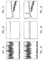
- Figure 1a shows the data set sorted into 0.01s bins.
- Figure 1b shows the autocorrelation function plotted over a lag of 0 to 50 seconds.
- Figure 1c shows the power spectrum. No trends are readily apparent from these presentations of the data set. However, the application of modulation with a sine factor of period 2 ⁇ seconds improves the results. In the case of Figure 2a, no apparent benefit is obtained as this result is indistinguishable from that of Figure 1a. However, the effect on the Figure 2b and 2c plots is that the factor allows them to reveal information not recognisable from Figure 1b or 1c.
- the sinusoidal variation are now readily apparent in the Figure 2b autocorrelation function plot and the frequency and power are derivable from the peak in the power plot, Figure 2c.
- Such a data set might arise from a rotating drum, with the transformation revealing the significant underlying pattern.
- the pattern could indicate heterogeneous distribution of sources in the drum - where there is significant variation with rotation - or homogeneous distribution - where there is no significant variation during rotation.
- Transformations of this type could also be used to reveal underlying patterns relevant to diagnostic issues.
- time and/or location specific information means that historical information can be considered to extract a range of useful further information and indications. Considerations in this area may be assisted by the type of transformation referred to in Example B above.
- a benefit of this approach is that it is possible to consider how a number of issues vary with time. Such issues include the variation of decay with time, the variation and/or extent of background signals with time and the like. Such considerations can be important in the context of standardisation issues, performing different algorithm comparisons on data and/or trend monitoring. Variations can be over a fairly short time scale or days/weeks. For instance, the approach may be used to consider detector performance variation and/or plant variation.
- the use of such signals in a passive neutron counting system to monitor a drum which is rotated can potentially be used to provide information on the spatial distribution of emitters within the drum.
- the neutron count time information is considered together with information on the rotation of the drum, for instance by means of the turntable rotation sensor output
- the neutron signal of a source should be represented by a sinusoidal variation in the signal, see Demonstration B2 above. Analysis of this variation can be used to suggest a source distribution tor the emitter in the drum.
- the present invention offers the potential to apply a more generalised approach to the consideration of signals detected by instruments.
- neutron coincidence counting is used, with the address of a detector being known for a neutron coincidence event detected.
- the spatial response function for the detectors involved is also known. From the combined data a probability map for the origins of that neutron can be generated. By doing this for each of a large number of neutrons and combining the results, the source distribution within the environment can be obtained.
- the counting efficiency for the detector array to this particular distribution can then be used to reach the mass of material in the sample result, with consequential improvement compared with the use of a global figure which was previously used irrespective of where the source position was suggested to be.
- the principal is demonstrated in more detail in Demonstration E2 below.
- detectors can be positioned at selected locations so as to inform on material within the plant and/or the movement of such material through the plant. This is based on changes in the detected counts with time.
- a first detector X may be positioned on a process stream A leading to process unit B.
- Further detectors Y and Z respectively may be provided on process streams C and D which lead away from process unit B.
- the count with time information is considered, the passage of a batch of material past detector X gives an increase from a level as the material passes, followed by a return to that level after the material passes.
- the relative levels of the increase for Y and Z can inform on the split.
- the relative levels can also indicate material hold up in the process unit B where the Y and Z information does not balance with the X information.
- the approach is used to consider a waste crate disposed between a number of neutron detectors, In this specific example, 6 groups each of four detectors are provided, but the principle is applicable if different numbers of groups and different numbers of detectors within those groups.
- the number of measurable quantities is limited to 31 count rates - 6 detector units x 4 detectors in each, individual count rates, + 6 detector units, unit count rates, + 1 overall system, system count rate. This limits the number of discrete sources of emissions within the environment that can have their spatial positions determined to 7 in theory and 2 or 3 in practice.
- each possible detector can be paired with each other detector, so giving 288 possible count rates for pairs and up to 17 minion distinct configurations. Whilst not all detector pairings will be useful, the additional data is most useful. The data level might even be sufficiently high to replace the discrete representation of neutron distribution with a continuous representation.
- cosmic events are known to have an impact on accuracy.
- the impact is potentially greater in some instrument types than others, but is more significant for all instruments, where those are operated at higher elevations and the shielding provided by the atmosphere is reduced as a result.
- the counts monitored are considered in blocks/segments and those blocks/segments having high multiplicities are discarded completely.
- correlated groups of neutrons can be considered as they arise, by virtue of their time stamp data, with multiplicities arising from cosmic events being discarded in real time.
- Validation of the fundamental approach, hardware operation and software operation are key aspects of any new instrument design. They are important not only to ensure the instrument is as accurate as possible, but also to convince regulators of the validity of the approach. New checks are periodically demanded by regulators. Attempts have been made to simulate the types and sequences of emissions an instrument will encounter, but the statistics of the process (randomness and time intervals) are difficult to simulate. Verification is frequently performed by trying the instrument out in actual measurements, but with the source position, activity etc know. Such validations and similar procedures used for calibration purposes are time consuming to perform.
- the historical data can be used as feed data to a verification and/or calibration process.
- the approach also allows the characteristics arising from deadtime to be presented to the instrument or alternatively allows deadtime to be measured and addressed in that way.
- the level of data obtained by the instrument for such a source can be compared with information from the previous characterisation of that source to establish whether the instrument generates false signals, and if it does the nature and potentially origin of those false signals. Improved knowledge of the instrument's response is obtained as a result.
- the historical information can be used to assist in development work and/or diagnostic work, where a body of realistic data is required.
- Present instruments perform a variety of calculations based upon the count arising within a certain period. A value is generated and the calculation moves on to the next period starting again. As the time sequence information for all the detectors is known in the present invention, however, the calculation could be based upon the count arising in a period of given length, up to that point in time. A rolling average would thus be used, rather than a series of fixed values. Improved accuracy should result, Such an approach could be used in a system such as the applicant's FISSTRACK® instrument.
- the present invention by virtue of the time information obtained, can provide greater information on the material's movement.
- a neutron emitting material approaching and passing a portal monitor will produce a signal which increases with time, peaks and then decreases with time.
- Information on the material's passage and at the time of its actually passing the portal monitor is obtained.
- a series of detectors could be considered together, with the signals and peaks for each informing on the time of passage of the material relative to each.
- the additional information the present invention provides also offers additional possibilities in the area of active neutron consideration.
- a pulsed neutron generator to introduce neutrons to an item.
- An array of detectors fast and/or thermal according to the invention detects these neutrons after their passage through the item and includes information on the time of detection. The time of detection compared with the time of the neutron pulse gives important information on the passage of the neutrons through the item.
- the measurements may be supplemented by passive neutron detection (such as reactor noise) and/or source jerk measurements.
- the use of spatially sensitive neutron detectors is also possible.
- the neutron pulse from the generator is detected upon arrival at the detector and is discriminated relative to background noise and the like by fast neutron coincidence of the neutron detector output with the neutron generator control pulse.
- Tomographic reconstruction algorithms online or offline, could be used to create images from the detected information.
Landscapes
- Physics & Mathematics (AREA)
- Health & Medical Sciences (AREA)
- Life Sciences & Earth Sciences (AREA)
- General Physics & Mathematics (AREA)
- High Energy & Nuclear Physics (AREA)
- Molecular Biology (AREA)
- Spectroscopy & Molecular Physics (AREA)
- Measurement Of Radiation (AREA)
- Transition And Organic Metals Composition Catalysts For Addition Polymerization (AREA)
- Analysing Materials By The Use Of Radiation (AREA)
- Glass Compositions (AREA)
- Crystals, And After-Treatments Of Crystals (AREA)
Applications Claiming Priority (1)
| Application Number | Priority Date | Filing Date | Title |
|---|---|---|---|
| GBGB0506605.5A GB0506605D0 (en) | 2005-03-31 | 2005-03-31 | Improvements in and relating to monitoring |
Publications (2)
| Publication Number | Publication Date |
|---|---|
| EP1707992A1 true EP1707992A1 (fr) | 2006-10-04 |
| EP1707992B1 EP1707992B1 (fr) | 2011-11-30 |
Family
ID=34586521
Family Applications (1)
| Application Number | Title | Priority Date | Filing Date |
|---|---|---|---|
| EP06251841A Expired - Lifetime EP1707992B1 (fr) | 2005-03-31 | 2006-03-31 | Améliorations concernant la surveillance d'émissions radioactives |
Country Status (5)
| Country | Link |
|---|---|
| US (1) | US7698099B2 (fr) |
| EP (1) | EP1707992B1 (fr) |
| JP (1) | JP2006284589A (fr) |
| AT (1) | ATE535825T1 (fr) |
| GB (2) | GB0506605D0 (fr) |
Cited By (1)
| Publication number | Priority date | Publication date | Assignee | Title |
|---|---|---|---|---|
| EP2299295A1 (fr) * | 2009-09-18 | 2011-03-23 | The European Atomic Energy Community (EURATOM), represented by the European Commission | Décompte de la multiplicité de neutrons |
Families Citing this family (5)
| Publication number | Priority date | Publication date | Assignee | Title |
|---|---|---|---|---|
| EP2891880B1 (fr) * | 2012-08-31 | 2020-01-01 | Kyoto University | Dispositif et procédé de détection de matière nucléaire |
| JP2015040814A (ja) * | 2013-08-23 | 2015-03-02 | 紀明 岡崎 | 放射線物質移動経路推定方法及び除染方法 |
| JP2015040815A (ja) * | 2013-08-23 | 2015-03-02 | 紀明 岡崎 | 放射線物質移動経路推定方法及び除染方法 |
| JP7397768B2 (ja) * | 2020-07-02 | 2023-12-13 | 日立Geニュークリア・エナジー株式会社 | 放射線計測装置および放射線計測方法 |
| KR102658742B1 (ko) * | 2021-11-09 | 2024-04-19 | 한국원자력연구원 | 핵종 농도 데이터 관리 장치 및 이를 포함하는 핵종 농도 검증 시스템 |
Citations (2)
| Publication number | Priority date | Publication date | Assignee | Title |
|---|---|---|---|---|
| US3889112A (en) | 1972-06-09 | 1975-06-10 | Commw Scient Ind Res Org | Method and apparatus for measuring the concentration of water, iron and aluminum in iron ore by neutron radiation |
| US6333958B1 (en) | 1999-09-21 | 2001-12-25 | James E. Stewart | Advanced electronics for faster time-correlation analysis of pulse sequences |
Family Cites Families (25)
| Publication number | Priority date | Publication date | Assignee | Title |
|---|---|---|---|---|
| US4396976A (en) * | 1972-09-11 | 1983-08-02 | Hyatt Gilbert P | System for interfacing a computer to a machine |
| US3902478A (en) * | 1971-01-07 | 1975-09-02 | Francis Konopasek | Disaster alarm |
| US3792470A (en) * | 1972-07-17 | 1974-02-12 | Johnson Service Co | Coded tone multiplexed alarm transmission system |
| US4402054A (en) * | 1980-10-15 | 1983-08-30 | Westinghouse Electric Corp. | Method and apparatus for the automatic diagnosis of system malfunctions |
| US4568514A (en) * | 1981-07-06 | 1986-02-04 | Gamma-Metrics | Fission chamber detector system for monitoring neutron flux in a nuclear reactor over an extra wide range, with high sensitivity in a hostile environment |
| US4391646A (en) * | 1982-02-25 | 1983-07-05 | Minnesota Mining And Manufacturing Company | Glass bubbles of increased collapse strength |
| US4677300A (en) * | 1984-08-03 | 1987-06-30 | Harshaw/Filtrol Partnership | Radiation detection and acquisition system |
| US5005142A (en) * | 1987-01-30 | 1991-04-02 | Westinghouse Electric Corp. | Smart sensor system for diagnostic monitoring |
| US4874951A (en) | 1987-07-13 | 1989-10-17 | Raymond Gold | Solid-state track recorder dosimetry device to measure absolute reaction rates and neutron fluence as a function of time |
| GB8802209D0 (en) * | 1988-02-02 | 1988-03-02 | Canadian Ind | Chemical foaming of emulsion explosive compositions |
| JPH07101474B2 (ja) * | 1988-10-20 | 1995-11-01 | ニッタン株式会社 | 監視警報装置 |
| US4931646A (en) * | 1989-03-17 | 1990-06-05 | The United States Of America As Represented By The Secretary Of The Army | Remote multichannel coincident nuclear detector and characterization system |
| JP3227224B2 (ja) * | 1992-10-09 | 2001-11-12 | 日本原子力研究所 | 光学フィルターによりシンチレータ出力パルス波高及び立ち上がり時間が制御可能なホスウィッチ検出器 |
| US5430663A (en) * | 1992-12-11 | 1995-07-04 | Vibrametrics, Inc. | Fault tolerant multipoint data collection system |
| US5437129A (en) * | 1993-01-13 | 1995-08-01 | Clear Plastics International, Inc. | Fire resistant skylight structure |
| US5347129A (en) | 1993-04-14 | 1994-09-13 | University Of Missouri-Columbia | System for determining the type of nuclear radiation from detector output pulse shape |
| US5440135A (en) * | 1993-09-01 | 1995-08-08 | Shonka Research Associates, Inc. | Self-calibrating radiation detectors for measuring the areal extent of contamination |
| US5854994A (en) * | 1996-08-23 | 1998-12-29 | Csi Technology, Inc. | Vibration monitor and transmission system |
| GB9910174D0 (en) * | 1999-05-04 | 1999-06-30 | British Nuclear Fuels Plc | Improvements in and relating to signal handling and processing |
| JP2002048898A (ja) * | 2000-08-02 | 2002-02-15 | Mitsubishi Heavy Ind Ltd | キャスク用モニタリング装置 |
| US20030115154A1 (en) * | 2001-12-18 | 2003-06-19 | Anderson Anne H. | System and method for facilitating operator authentication |
| JP4013134B2 (ja) * | 2002-11-05 | 2007-11-28 | 東洋紡績株式会社 | 放射性物質モニタリング材 |
| US7265353B2 (en) * | 2004-01-28 | 2007-09-04 | Ara, Inc. | Data acquisition, control, and spectral analysis software for multi-channel analyzers |
| JP4383947B2 (ja) * | 2004-04-15 | 2009-12-16 | 株式会社東芝 | 放射性ダストモニタ |
| US7049603B2 (en) | 2004-07-26 | 2006-05-23 | Temple University Of The Commonwealth System Of Higher Education | Neutron source detection camera |
-
2005
- 2005-03-31 GB GBGB0506605.5A patent/GB0506605D0/en not_active Ceased
-
2006
- 2006-03-31 US US11/395,461 patent/US7698099B2/en not_active Expired - Fee Related
- 2006-03-31 AT AT06251841T patent/ATE535825T1/de active
- 2006-03-31 GB GB0606480A patent/GB2424703B/en not_active Expired - Lifetime
- 2006-03-31 JP JP2006100815A patent/JP2006284589A/ja active Pending
- 2006-03-31 EP EP06251841A patent/EP1707992B1/fr not_active Expired - Lifetime
Patent Citations (2)
| Publication number | Priority date | Publication date | Assignee | Title |
|---|---|---|---|---|
| US3889112A (en) | 1972-06-09 | 1975-06-10 | Commw Scient Ind Res Org | Method and apparatus for measuring the concentration of water, iron and aluminum in iron ore by neutron radiation |
| US6333958B1 (en) | 1999-09-21 | 2001-12-25 | James E. Stewart | Advanced electronics for faster time-correlation analysis of pulse sequences |
Non-Patent Citations (5)
Cited By (3)
| Publication number | Priority date | Publication date | Assignee | Title |
|---|---|---|---|---|
| EP2299295A1 (fr) * | 2009-09-18 | 2011-03-23 | The European Atomic Energy Community (EURATOM), represented by the European Commission | Décompte de la multiplicité de neutrons |
| WO2011032743A1 (fr) * | 2009-09-18 | 2011-03-24 | The European Atomic Energy Community (Euratom), Represented By The European Commission | Comptage de multiplicités de neutrons |
| US8884212B2 (en) | 2009-09-18 | 2014-11-11 | Ludwig Holzleitner | Neutron multiplicity counting |
Also Published As
| Publication number | Publication date |
|---|---|
| GB0506605D0 (en) | 2005-05-11 |
| JP2006284589A (ja) | 2006-10-19 |
| GB2424703A (en) | 2006-10-04 |
| GB0606480D0 (en) | 2006-05-10 |
| EP1707992B1 (fr) | 2011-11-30 |
| US7698099B2 (en) | 2010-04-13 |
| ATE535825T1 (de) | 2011-12-15 |
| US20060219518A1 (en) | 2006-10-05 |
| GB2424703B (en) | 2010-03-24 |
Similar Documents
| Publication | Publication Date | Title |
|---|---|---|
| Choi et al. | Heterogeneity in meta-analyses: an unavoidable challenge worth exploring | |
| JP2008083037A (ja) | 放射線検出装置およびその効率校正方法 | |
| US9726766B2 (en) | Methods and databases for identifying nuclides | |
| US9201025B2 (en) | Absolute nuclear material assay using count distribution (LAMBDA) space | |
| EP1707992B1 (fr) | Améliorations concernant la surveillance d'émissions radioactives | |
| JP5523407B2 (ja) | 放射線検出装置及び検出方法 | |
| EP2478391B1 (fr) | Décompte de la multiplicité de neutrons | |
| JP6925842B2 (ja) | 放射能測定装置及び放射能測定方法 | |
| Cheng et al. | Time-interval distributions in a digital gamma multi-channel analyzer at extreme input rates | |
| US8729488B2 (en) | Assaying of waste | |
| Reva et al. | Mathematical models and algorithms of computer modeling of spectrometric signals | |
| US5550382A (en) | Process and apparatus for compacting informations to be stored and processing said compacted informations | |
| Hollas et al. | Determination of neutron multiplication of subcritical HEU systems using delayed neutrons | |
| CN121171648B (zh) | 一种基于多源数据的药品安全信号挖掘方法及系统 | |
| Tickner | Arbitrary perturbations in Monte Carlo neutral-particle transport | |
| Moore et al. | Methods for diagnosing and quantifying double pulsing in a Uranium Neutron Collar system using shift register logic | |
| CN120686301B (en) | Method and system for measuring ionizing radiation dosage based on pulse signals | |
| Wazzan | Higher-Order Statistics and Normalized Decay Analysis for Detector Deadtime Characterization | |
| Dodaro et al. | Passive Neutron Assay of Plutonium Materials: Monte Carlo Procedures to Simulate Generation of Neutron Pulse Trains and the Application of the Neutron Coincidence Counting Method | |
| Zhong et al. | Development of accurate and effective software for 4πβ—γ coincidence counting | |
| Wazzan et al. | Higher-order statistical analysis of inter-arrival times for radiation detector deadtime characterization and paralysis factor determination | |
| Luo | MuSun: muon capture on the deuteron | |
| Chen et al. | Parallel implementation of spectral pileup correction and Gaussian noise suppression using CUDA heterogeneous architecture | |
| Bourque et al. | Improving effective mass estimations in pu-metal annuli | |
| Nagy et al. | A Computational and Experimental Investigation of Multiplicity Counting with Continuous Fission Chamber Signals |
Legal Events
| Date | Code | Title | Description |
|---|---|---|---|
| PUAI | Public reference made under article 153(3) epc to a published international application that has entered the european phase |
Free format text: ORIGINAL CODE: 0009012 |
|
| AK | Designated contracting states |
Kind code of ref document: A1 Designated state(s): AT BE BG CH CY CZ DE DK EE ES FI FR GB GR HU IE IS IT LI LT LU LV MC NL PL PT RO SE SI SK TR |
|
| AX | Request for extension of the european patent |
Extension state: AL BA HR MK YU |
|
| 17P | Request for examination filed |
Effective date: 20070326 |
|
| 17Q | First examination report despatched |
Effective date: 20070509 |
|
| AKX | Designation fees paid |
Designated state(s): AT BE BG CH CY CZ DE DK EE ES FI FR GB GR HU IE IS IT LI LT LU LV MC NL PL PT RO SE SI SK TR |
|
| RAP1 | Party data changed (applicant data changed or rights of an application transferred) |
Owner name: VT NUCLEAR SERVICES LIMITED |
|
| GRAP | Despatch of communication of intention to grant a patent |
Free format text: ORIGINAL CODE: EPIDOSNIGR1 |
|
| GRAS | Grant fee paid |
Free format text: ORIGINAL CODE: EPIDOSNIGR3 |
|
| GRAA | (expected) grant |
Free format text: ORIGINAL CODE: 0009210 |
|
| AK | Designated contracting states |
Kind code of ref document: B1 Designated state(s): AT BE BG CH CY CZ DE DK EE ES FI FR GB GR HU IE IS IT LI LT LU LV MC NL PL PT RO SE SI SK TR |
|
| REG | Reference to a national code |
Ref country code: GB Ref legal event code: FG4D Ref country code: CH Ref legal event code: EP |
|
| REG | Reference to a national code |
Ref country code: IE Ref legal event code: FG4D |
|
| REG | Reference to a national code |
Ref country code: DE Ref legal event code: R096 Ref document number: 602006026120 Country of ref document: DE Effective date: 20120202 |
|
| REG | Reference to a national code |
Ref country code: NL Ref legal event code: VDEP Effective date: 20111130 |
|
| LTIE | Lt: invalidation of european patent or patent extension |
Effective date: 20111130 |
|
| PG25 | Lapsed in a contracting state [announced via postgrant information from national office to epo] |
Ref country code: LT Free format text: LAPSE BECAUSE OF FAILURE TO SUBMIT A TRANSLATION OF THE DESCRIPTION OR TO PAY THE FEE WITHIN THE PRESCRIBED TIME-LIMIT Effective date: 20111130 Ref country code: IS Free format text: LAPSE BECAUSE OF FAILURE TO SUBMIT A TRANSLATION OF THE DESCRIPTION OR TO PAY THE FEE WITHIN THE PRESCRIBED TIME-LIMIT Effective date: 20120330 |
|
| PGFP | Annual fee paid to national office [announced via postgrant information from national office to epo] |
Ref country code: FR Payment date: 20120403 Year of fee payment: 7 |
|
| PG25 | Lapsed in a contracting state [announced via postgrant information from national office to epo] |
Ref country code: BE Free format text: LAPSE BECAUSE OF FAILURE TO SUBMIT A TRANSLATION OF THE DESCRIPTION OR TO PAY THE FEE WITHIN THE PRESCRIBED TIME-LIMIT Effective date: 20111130 Ref country code: LV Free format text: LAPSE BECAUSE OF FAILURE TO SUBMIT A TRANSLATION OF THE DESCRIPTION OR TO PAY THE FEE WITHIN THE PRESCRIBED TIME-LIMIT Effective date: 20111130 Ref country code: GR Free format text: LAPSE BECAUSE OF FAILURE TO SUBMIT A TRANSLATION OF THE DESCRIPTION OR TO PAY THE FEE WITHIN THE PRESCRIBED TIME-LIMIT Effective date: 20120301 Ref country code: NL Free format text: LAPSE BECAUSE OF FAILURE TO SUBMIT A TRANSLATION OF THE DESCRIPTION OR TO PAY THE FEE WITHIN THE PRESCRIBED TIME-LIMIT Effective date: 20111130 Ref country code: PT Free format text: LAPSE BECAUSE OF FAILURE TO SUBMIT A TRANSLATION OF THE DESCRIPTION OR TO PAY THE FEE WITHIN THE PRESCRIBED TIME-LIMIT Effective date: 20120330 Ref country code: SE Free format text: LAPSE BECAUSE OF FAILURE TO SUBMIT A TRANSLATION OF THE DESCRIPTION OR TO PAY THE FEE WITHIN THE PRESCRIBED TIME-LIMIT Effective date: 20111130 Ref country code: SI Free format text: LAPSE BECAUSE OF FAILURE TO SUBMIT A TRANSLATION OF THE DESCRIPTION OR TO PAY THE FEE WITHIN THE PRESCRIBED TIME-LIMIT Effective date: 20111130 |
|
| PG25 | Lapsed in a contracting state [announced via postgrant information from national office to epo] |
Ref country code: CY Free format text: LAPSE BECAUSE OF FAILURE TO SUBMIT A TRANSLATION OF THE DESCRIPTION OR TO PAY THE FEE WITHIN THE PRESCRIBED TIME-LIMIT Effective date: 20111130 |
|
| PG25 | Lapsed in a contracting state [announced via postgrant information from national office to epo] |
Ref country code: SK Free format text: LAPSE BECAUSE OF FAILURE TO SUBMIT A TRANSLATION OF THE DESCRIPTION OR TO PAY THE FEE WITHIN THE PRESCRIBED TIME-LIMIT Effective date: 20111130 Ref country code: CZ Free format text: LAPSE BECAUSE OF FAILURE TO SUBMIT A TRANSLATION OF THE DESCRIPTION OR TO PAY THE FEE WITHIN THE PRESCRIBED TIME-LIMIT Effective date: 20111130 Ref country code: BG Free format text: LAPSE BECAUSE OF FAILURE TO SUBMIT A TRANSLATION OF THE DESCRIPTION OR TO PAY THE FEE WITHIN THE PRESCRIBED TIME-LIMIT Effective date: 20120229 Ref country code: EE Free format text: LAPSE BECAUSE OF FAILURE TO SUBMIT A TRANSLATION OF THE DESCRIPTION OR TO PAY THE FEE WITHIN THE PRESCRIBED TIME-LIMIT Effective date: 20111130 Ref country code: DK Free format text: LAPSE BECAUSE OF FAILURE TO SUBMIT A TRANSLATION OF THE DESCRIPTION OR TO PAY THE FEE WITHIN THE PRESCRIBED TIME-LIMIT Effective date: 20111130 |
|
| PG25 | Lapsed in a contracting state [announced via postgrant information from national office to epo] |
Ref country code: IT Free format text: LAPSE BECAUSE OF FAILURE TO SUBMIT A TRANSLATION OF THE DESCRIPTION OR TO PAY THE FEE WITHIN THE PRESCRIBED TIME-LIMIT Effective date: 20111130 Ref country code: RO Free format text: LAPSE BECAUSE OF FAILURE TO SUBMIT A TRANSLATION OF THE DESCRIPTION OR TO PAY THE FEE WITHIN THE PRESCRIBED TIME-LIMIT Effective date: 20111130 Ref country code: PL Free format text: LAPSE BECAUSE OF FAILURE TO SUBMIT A TRANSLATION OF THE DESCRIPTION OR TO PAY THE FEE WITHIN THE PRESCRIBED TIME-LIMIT Effective date: 20111130 |
|
| REG | Reference to a national code |
Ref country code: AT Ref legal event code: MK05 Ref document number: 535825 Country of ref document: AT Kind code of ref document: T Effective date: 20111130 |
|
| REG | Reference to a national code |
Ref country code: DE Ref legal event code: R119 Ref document number: 602006026120 Country of ref document: DE |
|
| PLBE | No opposition filed within time limit |
Free format text: ORIGINAL CODE: 0009261 |
|
| STAA | Information on the status of an ep patent application or granted ep patent |
Free format text: STATUS: NO OPPOSITION FILED WITHIN TIME LIMIT |
|
| PG25 | Lapsed in a contracting state [announced via postgrant information from national office to epo] |
Ref country code: MC Free format text: LAPSE BECAUSE OF NON-PAYMENT OF DUE FEES Effective date: 20120331 |
|
| REG | Reference to a national code |
Ref country code: CH Ref legal event code: PL |
|
| 26N | No opposition filed |
Effective date: 20120831 |
|
| REG | Reference to a national code |
Ref country code: DE Ref legal event code: R097 Ref document number: 602006026120 Country of ref document: DE Effective date: 20120831 |
|
| REG | Reference to a national code |
Ref country code: IE Ref legal event code: MM4A |
|
| PG25 | Lapsed in a contracting state [announced via postgrant information from national office to epo] |
Ref country code: IE Free format text: LAPSE BECAUSE OF NON-PAYMENT OF DUE FEES Effective date: 20120331 Ref country code: CH Free format text: LAPSE BECAUSE OF NON-PAYMENT OF DUE FEES Effective date: 20120331 Ref country code: AT Free format text: LAPSE BECAUSE OF FAILURE TO SUBMIT A TRANSLATION OF THE DESCRIPTION OR TO PAY THE FEE WITHIN THE PRESCRIBED TIME-LIMIT Effective date: 20111130 Ref country code: LI Free format text: LAPSE BECAUSE OF NON-PAYMENT OF DUE FEES Effective date: 20120331 |
|
| REG | Reference to a national code |
Ref country code: DE Ref legal event code: R119 Ref document number: 602006026120 Country of ref document: DE Effective date: 20121002 |
|
| PG25 | Lapsed in a contracting state [announced via postgrant information from national office to epo] |
Ref country code: ES Free format text: LAPSE BECAUSE OF FAILURE TO SUBMIT A TRANSLATION OF THE DESCRIPTION OR TO PAY THE FEE WITHIN THE PRESCRIBED TIME-LIMIT Effective date: 20120311 |
|
| PG25 | Lapsed in a contracting state [announced via postgrant information from national office to epo] |
Ref country code: FI Free format text: LAPSE BECAUSE OF FAILURE TO SUBMIT A TRANSLATION OF THE DESCRIPTION OR TO PAY THE FEE WITHIN THE PRESCRIBED TIME-LIMIT Effective date: 20111130 |
|
| REG | Reference to a national code |
Ref country code: FR Ref legal event code: ST Effective date: 20131129 |
|
| PG25 | Lapsed in a contracting state [announced via postgrant information from national office to epo] |
Ref country code: FR Free format text: LAPSE BECAUSE OF NON-PAYMENT OF DUE FEES Effective date: 20130402 |
|
| PG25 | Lapsed in a contracting state [announced via postgrant information from national office to epo] |
Ref country code: TR Free format text: LAPSE BECAUSE OF FAILURE TO SUBMIT A TRANSLATION OF THE DESCRIPTION OR TO PAY THE FEE WITHIN THE PRESCRIBED TIME-LIMIT Effective date: 20111130 |
|
| PG25 | Lapsed in a contracting state [announced via postgrant information from national office to epo] |
Ref country code: LU Free format text: LAPSE BECAUSE OF NON-PAYMENT OF DUE FEES Effective date: 20120331 |
|
| PG25 | Lapsed in a contracting state [announced via postgrant information from national office to epo] |
Ref country code: HU Free format text: LAPSE BECAUSE OF FAILURE TO SUBMIT A TRANSLATION OF THE DESCRIPTION OR TO PAY THE FEE WITHIN THE PRESCRIBED TIME-LIMIT Effective date: 20060331 |
|
| PG25 | Lapsed in a contracting state [announced via postgrant information from national office to epo] |
Ref country code: DE Free format text: LAPSE BECAUSE OF FAILURE TO SUBMIT A TRANSLATION OF THE DESCRIPTION OR TO PAY THE FEE WITHIN THE PRESCRIBED TIME-LIMIT Effective date: 20121002 |
|
| REG | Reference to a national code |
Ref country code: GB Ref legal event code: 732E Free format text: REGISTERED BETWEEN 20150416 AND 20150422 |
|
| PGFP | Annual fee paid to national office [announced via postgrant information from national office to epo] |
Ref country code: GB Payment date: 20180321 Year of fee payment: 13 |
|
| GBPC | Gb: european patent ceased through non-payment of renewal fee |
Effective date: 20190331 |
|
| PG25 | Lapsed in a contracting state [announced via postgrant information from national office to epo] |
Ref country code: GB Free format text: LAPSE BECAUSE OF NON-PAYMENT OF DUE FEES Effective date: 20190331 |