EP1708207A2 - Gerät zur Herstellung von Kabelbäumen mit grossem Querschnitt - Google Patents
Gerät zur Herstellung von Kabelbäumen mit grossem Querschnitt Download PDFInfo
- Publication number
- EP1708207A2 EP1708207A2 EP06006634A EP06006634A EP1708207A2 EP 1708207 A2 EP1708207 A2 EP 1708207A2 EP 06006634 A EP06006634 A EP 06006634A EP 06006634 A EP06006634 A EP 06006634A EP 1708207 A2 EP1708207 A2 EP 1708207A2
- Authority
- EP
- European Patent Office
- Prior art keywords
- cable
- tooling according
- harness
- tool
- terminal
- Prior art date
- Legal status (The legal status is an assumption and is not a legal conclusion. Google has not performed a legal analysis and makes no representation as to the accuracy of the status listed.)
- Granted
Links
- 238000005520 cutting process Methods 0.000 claims abstract description 9
- 238000002360 preparation method Methods 0.000 claims description 15
- 238000005192 partition Methods 0.000 claims description 12
- 238000004519 manufacturing process Methods 0.000 claims description 9
- 238000002788 crimping Methods 0.000 claims description 8
- 230000000903 blocking effect Effects 0.000 claims description 5
- 230000003100 immobilizing effect Effects 0.000 claims description 4
- 238000007493 shaping process Methods 0.000 claims description 3
- 210000004907 gland Anatomy 0.000 claims description 2
- 210000000056 organ Anatomy 0.000 claims description 2
- 239000004020 conductor Substances 0.000 claims 1
- 230000035515 penetration Effects 0.000 claims 1
- 238000007747 plating Methods 0.000 claims 1
- 238000009434 installation Methods 0.000 description 7
- 239000000969 carrier Substances 0.000 description 1
- 230000007547 defect Effects 0.000 description 1
- 238000006073 displacement reaction Methods 0.000 description 1
- 238000007373 indentation Methods 0.000 description 1
- 239000003550 marker Substances 0.000 description 1
- 230000008520 organization Effects 0.000 description 1
Images

Classifications
-
- H—ELECTRICITY
- H01—ELECTRIC ELEMENTS
- H01B—CABLES; CONDUCTORS; INSULATORS; SELECTION OF MATERIALS FOR THEIR CONDUCTIVE, INSULATING OR DIELECTRIC PROPERTIES
- H01B13/00—Apparatus or processes specially adapted for manufacturing conductors or cables
- H01B13/012—Apparatus or processes specially adapted for manufacturing conductors or cables for manufacturing wire harnesses
-
- Y—GENERAL TAGGING OF NEW TECHNOLOGICAL DEVELOPMENTS; GENERAL TAGGING OF CROSS-SECTIONAL TECHNOLOGIES SPANNING OVER SEVERAL SECTIONS OF THE IPC; TECHNICAL SUBJECTS COVERED BY FORMER USPC CROSS-REFERENCE ART COLLECTIONS [XRACs] AND DIGESTS
- Y10—TECHNICAL SUBJECTS COVERED BY FORMER USPC
- Y10T—TECHNICAL SUBJECTS COVERED BY FORMER US CLASSIFICATION
- Y10T29/00—Metal working
- Y10T29/49—Method of mechanical manufacture
- Y10T29/49002—Electrical device making
- Y10T29/49117—Conductor or circuit manufacturing
- Y10T29/49124—On flat or curved insulated base, e.g., printed circuit, etc.
- Y10T29/49155—Manufacturing circuit on or in base
- Y10T29/49162—Manufacturing circuit on or in base by using wire as conductive path
-
- Y—GENERAL TAGGING OF NEW TECHNOLOGICAL DEVELOPMENTS; GENERAL TAGGING OF CROSS-SECTIONAL TECHNOLOGIES SPANNING OVER SEVERAL SECTIONS OF THE IPC; TECHNICAL SUBJECTS COVERED BY FORMER USPC CROSS-REFERENCE ART COLLECTIONS [XRACs] AND DIGESTS
- Y10—TECHNICAL SUBJECTS COVERED BY FORMER USPC
- Y10T—TECHNICAL SUBJECTS COVERED BY FORMER US CLASSIFICATION
- Y10T29/00—Metal working
- Y10T29/51—Plural diverse manufacturing apparatus including means for metal shaping or assembling
- Y10T29/5136—Separate tool stations for selective or successive operation on work
- Y10T29/5137—Separate tool stations for selective or successive operation on work including assembling or disassembling station
- Y10T29/5139—Separate tool stations for selective or successive operation on work including assembling or disassembling station and means to sever work prior to disassembling
- Y10T29/514—Separate tool stations for selective or successive operation on work including assembling or disassembling station and means to sever work prior to disassembling comprising means to strip insulation from wire
-
- Y—GENERAL TAGGING OF NEW TECHNOLOGICAL DEVELOPMENTS; GENERAL TAGGING OF CROSS-SECTIONAL TECHNOLOGIES SPANNING OVER SEVERAL SECTIONS OF THE IPC; TECHNICAL SUBJECTS COVERED BY FORMER USPC CROSS-REFERENCE ART COLLECTIONS [XRACs] AND DIGESTS
- Y10—TECHNICAL SUBJECTS COVERED BY FORMER USPC
- Y10T—TECHNICAL SUBJECTS COVERED BY FORMER US CLASSIFICATION
- Y10T29/00—Metal working
- Y10T29/51—Plural diverse manufacturing apparatus including means for metal shaping or assembling
- Y10T29/5187—Wire working
-
- Y—GENERAL TAGGING OF NEW TECHNOLOGICAL DEVELOPMENTS; GENERAL TAGGING OF CROSS-SECTIONAL TECHNOLOGIES SPANNING OVER SEVERAL SECTIONS OF THE IPC; TECHNICAL SUBJECTS COVERED BY FORMER USPC CROSS-REFERENCE ART COLLECTIONS [XRACs] AND DIGESTS
- Y10—TECHNICAL SUBJECTS COVERED BY FORMER USPC
- Y10T—TECHNICAL SUBJECTS COVERED BY FORMER US CLASSIFICATION
- Y10T29/00—Metal working
- Y10T29/51—Plural diverse manufacturing apparatus including means for metal shaping or assembling
- Y10T29/5193—Electrical connector or terminal
-
- Y—GENERAL TAGGING OF NEW TECHNOLOGICAL DEVELOPMENTS; GENERAL TAGGING OF CROSS-SECTIONAL TECHNOLOGIES SPANNING OVER SEVERAL SECTIONS OF THE IPC; TECHNICAL SUBJECTS COVERED BY FORMER USPC CROSS-REFERENCE ART COLLECTIONS [XRACs] AND DIGESTS
- Y10—TECHNICAL SUBJECTS COVERED BY FORMER USPC
- Y10T—TECHNICAL SUBJECTS COVERED BY FORMER US CLASSIFICATION
- Y10T29/00—Metal working
- Y10T29/53—Means to assemble or disassemble
- Y10T29/5313—Means to assemble electrical device
- Y10T29/53187—Multiple station assembly apparatus
Definitions
- the invention is in the field of the manufacture of an electric cable, and more particularly of a harness with large sections. It relates to a tool for the manufacture of such a harness with large sections, including its setting in conformation and the equipment of its ends in connecting members.
- harnesses use drivers of large diameters, and generally have a high rigidity, which is likely to be variable along the length of the harness.
- Such harnesses are for example used for the wiring of rotorcraft, on which they are installed in defined positions.
- the rigidity of these harnesses does not allow, during their installation, to modify their conformation or their length, and offer only a very limited latitude of movement.
- these harnesses are likely to pass through partitions, and are equipped with fasteners to the latter. It appears that such harnesses must be prepared in the workshop prior to installation, by meeting strict specifications as to their length, or even the length of the various branches constituting them, as to their conformation, as to their equipment in connectors. terminals at their ends, both with regard to the positioning and orientation of these terminal connectors, and possibly as to the installation of at least one fastener, such as a partition passage element, in their central zone .
- Such tooling includes a work plan on which the harness extends while being held by modules, capable of to allow possibly twisting, and the installation of connecting members.
- modules comprise for example at least one input module and at least one output module for holding the corresponding ends of the harnesses for mounting the connecting members, between which input and output modules the harness is optionally twisted to its setting in conformation according to an apparent predefined plot on the work plan.
- the operator begins by stripping a starting end of the cable and installing the corresponding connection member.
- the starting end of the cable being installed on the input module, the operator puts in conformation the harness to the output module, where he installs the terminal connection member.
- fasteners especially for the passage of partitions are installed along the length of the harness.
- the object of the present invention is to propose a tool for the preparation of a harness with large sections, which facilitates the successive operations that an operator must perform for such a preparation and which makes it possible to control during the preparation of the cable its correspondence with the specifications to which it is subject. It is more particularly the object of the present invention to provide such tools equipped with assistance means for the operator at each of the stages of preparation of the harness, and means for checking its conformity at the end of manufacture of the harness.
- the tooling of the present invention is a tool for the preparation of a harness with large sections comprising at least one conductive cable.
- This tool is intended to conform the harness and to place organs on the harness including at least starting and terminal connection members respectively assigned to a starting end of the cable and to an end of the cable.
- This tooling includes a worktop supporting a plurality of harness holding modules, including at least one input module for holding the starting end of the cable and at least one output module for holding the end. terminal of the cable.
- the output body is movably mounted on the work plane to alternatively present the tools which it is carrying next to the arrival position in front of the output module of the cable end end.
- the third tool is in particular mounted movably on the output body to control the correct length of the cable, and the position and orientation of the terminal connection member. This control is performed in a tolerance range corresponding to the extreme positions of mobility of the third tool on the output body.
- the third tool is more particularly mounted mobile on the output body in at least one direction corresponding to the orientation of the terminal end of the harness.
- the first tool advantageously comprises a first passage passage of the terminal end of the cable, at least partially between two walls.
- the proximal and distal ends of this first corridor are open to allow the passage of the cable regardless of its length.
- the distal end of this first corridor forms a marking of the cutting length of the cable, at least one mark formed on this first corridor indicating a stripping position of the terminal end of the cable.
- the first corridor is more particularly provided with at least two pins of respective cable stripping positions.
- the proximal end of the first corridor is in particular a stripping mark of the cable.
- the first passage is for example formed between the flanges of a U-shaped section.
- the distal end of the bottom of this profile is the reference length of the cable cut.
- At least one indentation of its side walls constitutes a first stripping mark.
- the proximal end of the profile constitutes a second stripping mark.
- these each comprise a second reception corridor of the terminal connection member and means for holding the latter by interlocking.
- the second reception passages of the terminal connection member are advantageously formed between the walls of a U-shaped section.
- the terminal connection member being a lug
- the holding means of this lug consist for example of a pin.
- the connecting member is likely to be a coaxial connection member.
- the holding means of this coaxial connection member are for example constituted by at least one bearing formed at the distal end of the second corridor.
- the output module preferably comprises a fourth tool movably mounted on the output body for controlling the position and orientation of the connector body in a tolerance range corresponding to the positions. extreme mobility of the fourth tool on the output body. It will be noted that several connection members are capable of being inserted into the same connector body.
- the output body is a carriage mounted to move in translation on the working plane laterally to the orientation of the terminal end of the cable.
- the output body is a turret mounted to rotate on the work plane. This turret is equipped with first locking means in angular position according to the positions of the various tools.
- the first blocking means consist for example of an index carried by the turret, which cooperates with housings formed on the work plan.
- the input module preferably comprises means for receiving the starting connection member, or, if appropriate, a starting connector body inside which at least one starting connection member is inserted, and second blocking means of the latter inside the receiving means.
- the receiving means of the starting connection member, or if necessary the starting connector body consist for example of a shoe housing this starting connection member or this starting connector body.
- the second locking means are, for example, constituted by a plunger spring button of the starting connection member or the starting connector body inside the shoe.
- the starting module comprises a tool for marking at least one stripping length of the starting end of the cable.
- This locating tool is for example constituted by a third reception corridor of the starting end of the cable.
- This third passage is advantageously blind at its distal end, to form a stop member of the end of the cable.
- the walls of this third corridor are particularly carriers of at least one stripping mark.
- the proximal end of the third passage advantageously constitutes a second stripping mark.
- the walls of the third corridor have between their distal and proximal ends at least one shoulder forming a stripping mark.
- the tooling comprises at least one intermediate module for the establishment on the harness of a fastener.
- This intermediate module more particularly comprises at least one support of the fastener and third locking means of this fastener on the support.
- the fastener being in particular a means for gripping the harness comprising a wall
- the support is formed of a first body having rails for receiving said wall
- the third locking means being constituted by a second body fixed on the work plane.
- the fixing member is for example a partition passage element provided with at least one heat-shrinkable sheath to grip the harness, or a cable gland or other equivalent means to grip the harness.
- the tooling is capable of comprising at least one pair of intermediate modules. These modules are cooperating, and are oriented concurrently for, a fastener having been placed on the harness by means of a first intermediate module, remove the harness from the worktop and place the fastener on the second intermediate module to continue the preparation of the harness notwithstanding a possible change of harness extension plan.
- the work plan includes an extension of the harness to facilitate guiding the operator in shaping the harness.
- This route also has identification marks for the establishment on the harness of a color marker used during the assembly of the harness on site.
- the work plan is likely to include guide guides of the harness for its setting in conformation.
- the work plan consists of a removable tray attached to a table.
- This tray corresponds to a set of trays relative to the preparation of respective harnesses, these trays being arranged on a rack arranged near the table.
- the table preferably comprises means for positioning and immobilizing the plate, in particular for against any twisting efforts exerted on the harness during its preparation.
- the means for positioning and immobilizing the plate combine, for example, guides for guiding the plate to at least one of its sides and locking members of the plate bearing against these slides.
- the plate locking members are for example constituted by eccentric stops disposed at the edge of the plate opposite to that by which it bears against the slideways.
- the harness is likely to be equipped at each end of one or more connecting members inserted into a respective connector body. It will be understood in this that the harness is likely to be equipped with connector bodies respectively start and terminal, which house at least one connection member respectively start and terminal.
- a tool is intended for the preparation of a harness with large sections comprising at least one cable.
- a preparation consists in particular in crimping start and end connection members to the corresponding ends of the cable, or even possibly to set up an intermediate fixing member, such as a partition passage element.
- the connecting members will in particular be integrated in a connector body.
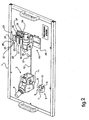
- This tool comprises a work plan formed of a plate 1.
- a plate 1 is intended to be fixed on a work table.
- a plurality of trays is for example stored on a rack, the operator choosing the one corresponding to his needs and fixing it on the table.
- the latter not shown in the figures, has means for fixing the plate 1, to hold it firmly against possible twisting forces of the cables constituting the harness, during the preparation of the latter.
- the tray 1 is equipped with at least one starting module 2.
- This starting module 2 comprises a shoe 3 for receiving a starting connector body 4.
- At least one connecting member is integrated in the connector body 4 and is crimped on the cable.
- the operator has in a prior step a tool 5 for marking the stripping lengths of the starting end of the cable.
- This tool 5, disposed near the shoe 3, is formed of a U-shaped part whose side walls 6 form a third corridor 10 receiving the starting end of the cable, and whose bottom 7 constitutes a stop member against which bears the end of the cable.
- This U-shaped piece 5 has a shoulder 8 forming a first stripping mark, the distal end 9 of the third passage 10 forming a second stripping mark.
- the operator installs the starting end of the cable inside the third corridor 10, and marks by marking on the cable the locations of the different stripping lengths. Then the operator removes the starting end of the cable, crimp the connection member and introduces the connection member in the body of the corresponding connector 4.
- the operator installs the starting end of the cable equipped with the connector body 4 in the shoe 3 of the starting module 2.
- This shoe 3 is equipped with a second locking means of the connector body 4, constituted on the exemplary embodiment illustrated by a plunger pin 11 of the connector body 4 inside the shoe 3. It will be noted on the embodiment illustrated in FIG. 3 that the tooling comprises two such modules 2, for receiving the starting end of respective cables.
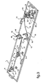
- the harness is then shaped according to a marking 12 traced on the surface of the plate 1.
- the plate 1 is equipped with supports 13 or 14 for guiding the harness along its path. 12.
- a partition passage member is provided to be installed on the harness between its two ends.
- a partition passage element not shown in the figure, currently comprises a tray and heat-shrinkable sleeves for gripping the cables of the harness.
- the plate 1 is equipped with an intermediate module 15.
- This intermediate module 15 comprises a support 16 of the partition passage element and third means of blocking of the latter on the partition element.
- the support is formed of a first body having slideways 17 for receiving the edges of the plate of the partition passage element, while the third locking means consist of a second body 18 fixed on the plate 1.
- L Part wall passing element being installed on the harness, the latter is removed from the plate 1 to install the partition element in another intermediate module 15 adjacent the previous and oriented concurrently.
- the cable is then shaped according to the pattern 12 marked on the surface of the plate 1.
- the plate 1 is equipped with an output module 19.
- the latter comprises an output body 20 movably mounted on the plate 1.
- this body 20 is organized in a carriage mounted to move in translation on the plate 1 in a lateral direction at the end end of the cable.
- the output body 20 is organized in a turret mounted to rotate on the plate 1.
- This turret 20 is equipped with first locking means in different angular positions, constituted on the example illustrated by an index 21 carried by the turret 20 cooperating with housings formed on the plate 1.
- the output body 20 is equipped with at least three tools.
- a first tool 22 is intended for marking the cutting length of the end of the cable, and for marking the different stripping lengths. More particularly, this first tool 22 is shaped as a first corridor 23 for receiving the terminal end of the cable. This first passage 23 is for example delimited between the walls 24 of a U-shaped section. The distal end 25 of the first corridor 23 constitutes a cutting mark of the terminal end of the cable.
- the profile comprises a first reference 26 of stripping length. In Figure 1, the first marking 26 of stripping is formed by a notch formed in the walls 24 of the profile. In Figure 2, the first marking 26 of stripping is formed by a mark formed on the edge of the walls 24 of the profile.
- the proximal end 27 of the first passage 23 constitutes a second stripping mark. The operator having marked on the cable the different lengths of cutting and stripping, it removes the terminal end of the cable from the first tool 22 to cut and stripping this end.
- the operator then has a second tool 28 formed on the output body 20.
- This second tool 28 is intended to receive a connection member 29, to maintain it to the required length and orientation.
- the operator installs the terminal end of the previously stripped cable on the connection member 29, then proceeds to crimp the latter.
- the output body 20 comprises a third tool 30, for controlling the position and orientation of the connection member 29, and for controlling the required length of the cable. It will be noted that the position of this third tool 30 is shifted rearwardly with respect to the previous one, due to the elongation of the cable caused during the crimping operation. This third tool 30 is intended to receive the connection member 29 previously crimped onto the cable.
- the second tool 28 and the third tool 30 each comprise a third passage 31 and 32 formed between the walls of a U-shaped section. These third passages 31 and 32 are intended to receive the connection member. 29, and are equipped with holding means by interlocking the latter.
- the connection member 29 is a terminal, and the means for holding this terminal are formed by a pin 33.
- the connection member 29 is a coaxial connector, and the means for holding this connection member 29 consist of at least one bearing 34 arranged at the distal end of the third passages 31 and 32.
- the third tool 30 is mounted movably on the output body 20, so that the conformity check of the cable is carried out by the possibility of installing or not the connection member 29 on the third tool 30 in the range of mobility of the latter between its extreme positions. It follows that the conformity of the cable is checked directly by the tool used for its manufacture, from a simple operation of installation of the terminal connection member 29 on the third tool.
- connection member 29 is integrated in a connector 35.
- the output module 19 comprises a fourth tool 36 mounted to move on the output body 20 like the third tool 30, for controlling the position and orientation of the connector body 35 in the mobility range of the fourth tool 36 on the output body 20.
- the line 12 that comprises the surface of the plate 1 includes registration marks 37 for the positioning on the harness of color markers, such as ribbons, used during the installation of the harness. on the site.
Landscapes
- Engineering & Computer Science (AREA)
- Manufacturing & Machinery (AREA)
- Manufacturing Of Electrical Connectors (AREA)
- Installation Of Indoor Wiring (AREA)
- Processing Of Terminals (AREA)
Applications Claiming Priority (1)
| Application Number | Priority Date | Filing Date | Title |
|---|---|---|---|
| FR0503230A FR2884036B1 (fr) | 2005-04-01 | 2005-04-01 | Outillage pour la fabrication de harnais rigides a grosses sections |
Publications (3)
| Publication Number | Publication Date |
|---|---|
| EP1708207A2 true EP1708207A2 (de) | 2006-10-04 |
| EP1708207A3 EP1708207A3 (de) | 2015-08-19 |
| EP1708207B1 EP1708207B1 (de) | 2017-11-08 |
Family
ID=35149645
Family Applications (1)
| Application Number | Title | Priority Date | Filing Date |
|---|---|---|---|
| EP06006634.7A Expired - Lifetime EP1708207B1 (de) | 2005-04-01 | 2006-03-30 | Gerät zur Herstellung von Kabelbäumen mit grossem Querschnitt |
Country Status (5)
| Country | Link |
|---|---|
| US (1) | US7266877B2 (de) |
| EP (1) | EP1708207B1 (de) |
| CN (1) | CN1921030B (de) |
| AU (1) | AU2006201351B2 (de) |
| FR (1) | FR2884036B1 (de) |
Cited By (1)
| Publication number | Priority date | Publication date | Assignee | Title |
|---|---|---|---|---|
| CN108955536A (zh) * | 2018-07-28 | 2018-12-07 | 天津市华之阳特种线缆有限公司 | 一种具有标记功能的微型连接器用定位检测系统 |
Families Citing this family (7)
| Publication number | Priority date | Publication date | Assignee | Title |
|---|---|---|---|---|
| FR2880465A1 (fr) * | 2004-12-30 | 2006-07-07 | Eurocopter France | Procede et dispositif de fabrication de harnais electriques |
| US9484722B2 (en) * | 2009-03-23 | 2016-11-01 | Southwire Company, Llc | Pulling head assembly workstation |
| WO2011046998A1 (en) | 2009-10-14 | 2011-04-21 | Southwire Company | Pulling head assembly workstation |
| EP3447859B1 (de) | 2017-08-21 | 2020-10-07 | Aptiv Technologies Limited | Drahtschneidgerät zum zerschneiden eines drahts und zum verknüpfen der enden |
| GB201718239D0 (en) | 2017-11-03 | 2017-12-20 | Rolls Royce Plc | A clocking and angle setting tool for a wire harness and method |
| CN113369848B (zh) * | 2021-06-30 | 2023-05-26 | 苏州欧菲特电子股份有限公司 | 一种过盈线扣的穿线工装 |
| CN119742620B (zh) * | 2025-03-04 | 2025-05-13 | 浙江六环电缆科技股份有限公司 | 一种电缆快速连接设备及其连接方法 |
Family Cites Families (17)
| Publication number | Priority date | Publication date | Assignee | Title |
|---|---|---|---|---|
| IT961759B (it) * | 1971-08-02 | 1973-12-10 | Hickman R | Perfezionamento nelle strutture di serraggio per pezzi in lavo razione |
| US4107838A (en) * | 1976-01-07 | 1978-08-22 | Western Electric Company, Incorporated | Arranging randomly positioned articles into preselected positions |
| GB1551056A (en) * | 1976-04-26 | 1979-08-22 | Draftex Dev Ag | Channel shaped sealing guiding or finishing strips and the like |
| US4126935A (en) * | 1977-05-31 | 1978-11-28 | Bell Telephone Laboratories, Incorporated | Method and apparatus for manufacturing wiring harnesses |
| US4446615A (en) * | 1982-03-16 | 1984-05-08 | Eubanks Engineering Company | Apparatus for attaching terminals to the ends of electric conductors |
| EP0126131A1 (de) * | 1982-11-19 | 1984-11-28 | GORJAT, Jean | Werkzeugträger |
| US4554725A (en) * | 1983-05-25 | 1985-11-26 | Amp Incorporated | Modular lead maker |
| US4677734A (en) * | 1983-10-07 | 1987-07-07 | The Boeing Company | Robotic wire harness assembly system |
| US4512828A (en) * | 1983-12-27 | 1985-04-23 | Emanuel Helm | Cable holding and positioning apparatus and splicing method |
| CA2023131C (en) * | 1989-08-17 | 1999-10-19 | Mecanismos Auxiliares Industriales, S.A. | Wire harness manufacture |
| US4965929A (en) * | 1989-08-17 | 1990-10-30 | Mecanismos Auxiliares Industriales, S.A. | System for fabrication of wire harness |
| US5016345A (en) * | 1989-08-17 | 1991-05-21 | Mecanismos Auxiliares Industriales, S.A. | Apparatus for assembling wire harnesses |
| JP2976746B2 (ja) * | 1993-03-12 | 1999-11-10 | 住友電装株式会社 | コネクタハウジングの位置決め装置 |
| DE4321007A1 (de) * | 1993-06-24 | 1995-01-05 | Kloeckner Moeller Gmbh | Konfektioniertes Kabel, insbesondere für den Schaltschrank- und Steuerungsbau, Verfahren zu seiner Bearbeitung und Bearbeitungsvorrichtung hierfür |
| FR2758902B1 (fr) * | 1997-01-30 | 1999-04-09 | Setic Sa Soc Nouv | Machine d'assemblage par torsion de cables conducteurs |
| FR2787937B1 (fr) * | 1998-12-23 | 2001-03-02 | Siemens Automotive Sa | Unite de sertissage automatique de nappes de cables plats flexibles et procede de sertissage correspondant |
| CN2645184Y (zh) * | 2002-12-04 | 2004-09-29 | 蔡政郎 | 用于制作线材的装置 |
-
2005
- 2005-04-01 FR FR0503230A patent/FR2884036B1/fr not_active Expired - Fee Related
-
2006
- 2006-03-30 EP EP06006634.7A patent/EP1708207B1/de not_active Expired - Lifetime
- 2006-03-31 AU AU2006201351A patent/AU2006201351B2/en not_active Ceased
- 2006-04-03 US US11/395,246 patent/US7266877B2/en not_active Expired - Fee Related
- 2006-04-03 CN CN2006101213975A patent/CN1921030B/zh not_active Expired - Fee Related
Cited By (1)
| Publication number | Priority date | Publication date | Assignee | Title |
|---|---|---|---|---|
| CN108955536A (zh) * | 2018-07-28 | 2018-12-07 | 天津市华之阳特种线缆有限公司 | 一种具有标记功能的微型连接器用定位检测系统 |
Also Published As
| Publication number | Publication date |
|---|---|
| US20060223353A1 (en) | 2006-10-05 |
| CN1921030A (zh) | 2007-02-28 |
| AU2006201351A1 (en) | 2006-10-19 |
| CN1921030B (zh) | 2010-05-12 |
| EP1708207A3 (de) | 2015-08-19 |
| US7266877B2 (en) | 2007-09-11 |
| FR2884036A1 (fr) | 2006-10-06 |
| AU2006201351B2 (en) | 2009-10-29 |
| EP1708207B1 (de) | 2017-11-08 |
| FR2884036B1 (fr) | 2007-05-18 |
Similar Documents
| Publication | Publication Date | Title |
|---|---|---|
| US7575269B2 (en) | Connector connecting construction, a clamping member and a method of mounting a connector connecting construction | |
| US20160288740A1 (en) | Wire harness routing device for sliding seat | |
| EP2693244A1 (de) | Vorrichtung zum entfernen einer glasfaserbeschichtung und verfahren zum entfernen der beschichtung | |
| EP1708207B1 (de) | Gerät zur Herstellung von Kabelbäumen mit grossem Querschnitt | |
| JP6850612B2 (ja) | 磁気コイル用コネクタ | |
| JPH08185919A (ja) | リヤホルダ一体型コネクタ | |
| WO2013132445A1 (en) | Optic cable stripping auxiliary tool | |
| US7581320B2 (en) | Method for connecting component delivery tapes, structure of the connection, and scissors for component delivery tape, used for the connection method | |
| JP2009069293A (ja) | 光コネクタ組立治具 | |
| EP1574285B1 (de) | Regeleinrichtung für zwei getrennte Stangenzuführvorrichtungen | |
| CN101180151A (zh) | 工具适配器 | |
| EP2648939A1 (de) | Leitung zur aufnahme von länglichen elementen, montageverfahren dafür und anordnung mit einer halterung und einer solchen leitung | |
| EP1708315A2 (de) | Vielfachsteckverbinder | |
| FR3023753A1 (fr) | Dispositif magnetique pour le support et le guidage de cables. | |
| JP2013015745A (ja) | 光コネクタ | |
| EP3601025B1 (de) | Vorbereitungsgestell für fahrzeugmontage und verfahren zur montage eines fahrzeugs | |
| EP2812230A1 (de) | Struktur zum aufbau einer fahrzeuglenkerposition | |
| US5852958A (en) | Device for removing an end coating portion | |
| JP6736783B2 (ja) | ストリップ組立体に使用するための取付装置、及びストリップ組立体によって実施される方法 | |
| EP0557398B1 (de) | Führungsverfahren und -apparat zum automatischen einführen eines männlichen teils in ein weibliches teil | |
| JP5492839B2 (ja) | メカニカルスプライスおよびケース付きピグテイル光ファイバ、光ファイバ接続装置及び光ファイバ接続方法 | |
| EP3049317A1 (de) | Vorrichtung zum nachbessern eines fahrzeugkarosserieelements | |
| FR3092028A1 (fr) | Gabarit de positionnement d'une rotule à l'intérieur d'un boîtier de montage d'un outil sur une tête de préhension pour manipulateur. | |
| EP2904896A1 (de) | Festhaltung für eine Messkluppe | |
| JP5995618B2 (ja) | 油圧ホース用切断圧入ユニット |
Legal Events
| Date | Code | Title | Description |
|---|---|---|---|
| PUAI | Public reference made under article 153(3) epc to a published international application that has entered the european phase |
Free format text: ORIGINAL CODE: 0009012 |
|
| AK | Designated contracting states |
Kind code of ref document: A2 Designated state(s): AT BE BG CH CY CZ DE DK EE ES FI FR GB GR HU IE IS IT LI LT LU LV MC NL PL PT RO SE SI SK TR |
|
| AX | Request for extension of the european patent |
Extension state: AL BA HR MK YU |
|
| RAP1 | Party data changed (applicant data changed or rights of an application transferred) |
Owner name: AIRBUS HELICOPTERS |
|
| PUAL | Search report despatched |
Free format text: ORIGINAL CODE: 0009013 |
|
| AK | Designated contracting states |
Kind code of ref document: A3 Designated state(s): AT BE BG CH CY CZ DE DK EE ES FI FR GB GR HU IE IS IT LI LT LU LV MC NL PL PT RO SE SI SK TR |
|
| AX | Request for extension of the european patent |
Extension state: AL BA HR MK YU |
|
| RIC1 | Information provided on ipc code assigned before grant |
Ipc: H01R 43/28 20060101ALI20150716BHEP Ipc: H01B 13/012 20060101AFI20150716BHEP Ipc: H01R 43/05 20060101ALI20150716BHEP |
|
| 17P | Request for examination filed |
Effective date: 20151006 |
|
| RBV | Designated contracting states (corrected) |
Designated state(s): AT BE BG CH CY CZ DE DK EE ES FI FR GB GR HU IE IS IT LI LT LU LV MC NL PL PT RO SE SI SK TR |
|
| AKX | Designation fees paid |
Designated state(s): AT BE BG CH CY CZ DE DK EE ES FI FR GB GR HU IE IS IT LI LT LU LV MC NL PL PT RO SE SI SK TR |
|
| AXX | Extension fees paid |
Extension state: MK Extension state: BA Extension state: HR Extension state: YU Extension state: AL |
|
| 17Q | First examination report despatched |
Effective date: 20160721 |
|
| GRAP | Despatch of communication of intention to grant a patent |
Free format text: ORIGINAL CODE: EPIDOSNIGR1 |
|
| INTG | Intention to grant announced |
Effective date: 20170803 |
|
| GRAS | Grant fee paid |
Free format text: ORIGINAL CODE: EPIDOSNIGR3 |
|
| GRAA | (expected) grant |
Free format text: ORIGINAL CODE: 0009210 |
|
| AK | Designated contracting states |
Kind code of ref document: B1 Designated state(s): AT BE BG CH CY CZ DE DK EE ES FI FR GB GR HU IE IS IT LI LT LU LV MC NL PL PT RO SE SI SK TR |
|
| REG | Reference to a national code |
Ref country code: GB Ref legal event code: FG4D Free format text: NOT ENGLISH |
|
| REG | Reference to a national code |
Ref country code: CH Ref legal event code: EP Ref country code: AT Ref legal event code: REF Ref document number: 944884 Country of ref document: AT Kind code of ref document: T Effective date: 20171115 |
|
| REG | Reference to a national code |
Ref country code: IE Ref legal event code: FG4D Free format text: LANGUAGE OF EP DOCUMENT: FRENCH |
|
| REG | Reference to a national code |
Ref country code: DE Ref legal event code: R096 Ref document number: 602006054019 Country of ref document: DE |
|
| REG | Reference to a national code |
Ref country code: NL Ref legal event code: MP Effective date: 20171108 |
|
| REG | Reference to a national code |
Ref country code: LT Ref legal event code: MG4D |
|
| REG | Reference to a national code |
Ref country code: AT Ref legal event code: MK05 Ref document number: 944884 Country of ref document: AT Kind code of ref document: T Effective date: 20171108 |
|
| PG25 | Lapsed in a contracting state [announced via postgrant information from national office to epo] |
Ref country code: SE Free format text: LAPSE BECAUSE OF FAILURE TO SUBMIT A TRANSLATION OF THE DESCRIPTION OR TO PAY THE FEE WITHIN THE PRESCRIBED TIME-LIMIT Effective date: 20171108 Ref country code: NL Free format text: LAPSE BECAUSE OF FAILURE TO SUBMIT A TRANSLATION OF THE DESCRIPTION OR TO PAY THE FEE WITHIN THE PRESCRIBED TIME-LIMIT Effective date: 20171108 Ref country code: LT Free format text: LAPSE BECAUSE OF FAILURE TO SUBMIT A TRANSLATION OF THE DESCRIPTION OR TO PAY THE FEE WITHIN THE PRESCRIBED TIME-LIMIT Effective date: 20171108 Ref country code: ES Free format text: LAPSE BECAUSE OF FAILURE TO SUBMIT A TRANSLATION OF THE DESCRIPTION OR TO PAY THE FEE WITHIN THE PRESCRIBED TIME-LIMIT Effective date: 20171108 Ref country code: FI Free format text: LAPSE BECAUSE OF FAILURE TO SUBMIT A TRANSLATION OF THE DESCRIPTION OR TO PAY THE FEE WITHIN THE PRESCRIBED TIME-LIMIT Effective date: 20171108 |
|
| PG25 | Lapsed in a contracting state [announced via postgrant information from national office to epo] |
Ref country code: AT Free format text: LAPSE BECAUSE OF FAILURE TO SUBMIT A TRANSLATION OF THE DESCRIPTION OR TO PAY THE FEE WITHIN THE PRESCRIBED TIME-LIMIT Effective date: 20171108 Ref country code: IS Free format text: LAPSE BECAUSE OF FAILURE TO SUBMIT A TRANSLATION OF THE DESCRIPTION OR TO PAY THE FEE WITHIN THE PRESCRIBED TIME-LIMIT Effective date: 20180308 Ref country code: GR Free format text: LAPSE BECAUSE OF FAILURE TO SUBMIT A TRANSLATION OF THE DESCRIPTION OR TO PAY THE FEE WITHIN THE PRESCRIBED TIME-LIMIT Effective date: 20180209 Ref country code: BG Free format text: LAPSE BECAUSE OF FAILURE TO SUBMIT A TRANSLATION OF THE DESCRIPTION OR TO PAY THE FEE WITHIN THE PRESCRIBED TIME-LIMIT Effective date: 20180208 Ref country code: LV Free format text: LAPSE BECAUSE OF FAILURE TO SUBMIT A TRANSLATION OF THE DESCRIPTION OR TO PAY THE FEE WITHIN THE PRESCRIBED TIME-LIMIT Effective date: 20171108 |
|
| PG25 | Lapsed in a contracting state [announced via postgrant information from national office to epo] |
Ref country code: CZ Free format text: LAPSE BECAUSE OF FAILURE TO SUBMIT A TRANSLATION OF THE DESCRIPTION OR TO PAY THE FEE WITHIN THE PRESCRIBED TIME-LIMIT Effective date: 20171108 Ref country code: SK Free format text: LAPSE BECAUSE OF FAILURE TO SUBMIT A TRANSLATION OF THE DESCRIPTION OR TO PAY THE FEE WITHIN THE PRESCRIBED TIME-LIMIT Effective date: 20171108 Ref country code: CY Free format text: LAPSE BECAUSE OF FAILURE TO SUBMIT A TRANSLATION OF THE DESCRIPTION OR TO PAY THE FEE WITHIN THE PRESCRIBED TIME-LIMIT Effective date: 20171108 Ref country code: EE Free format text: LAPSE BECAUSE OF FAILURE TO SUBMIT A TRANSLATION OF THE DESCRIPTION OR TO PAY THE FEE WITHIN THE PRESCRIBED TIME-LIMIT Effective date: 20171108 Ref country code: DK Free format text: LAPSE BECAUSE OF FAILURE TO SUBMIT A TRANSLATION OF THE DESCRIPTION OR TO PAY THE FEE WITHIN THE PRESCRIBED TIME-LIMIT Effective date: 20171108 |
|
| REG | Reference to a national code |
Ref country code: DE Ref legal event code: R097 Ref document number: 602006054019 Country of ref document: DE |
|
| PG25 | Lapsed in a contracting state [announced via postgrant information from national office to epo] |
Ref country code: RO Free format text: LAPSE BECAUSE OF FAILURE TO SUBMIT A TRANSLATION OF THE DESCRIPTION OR TO PAY THE FEE WITHIN THE PRESCRIBED TIME-LIMIT Effective date: 20171108 Ref country code: PL Free format text: LAPSE BECAUSE OF FAILURE TO SUBMIT A TRANSLATION OF THE DESCRIPTION OR TO PAY THE FEE WITHIN THE PRESCRIBED TIME-LIMIT Effective date: 20171108 |
|
| PLBE | No opposition filed within time limit |
Free format text: ORIGINAL CODE: 0009261 |
|
| STAA | Information on the status of an ep patent application or granted ep patent |
Free format text: STATUS: NO OPPOSITION FILED WITHIN TIME LIMIT |
|
| REG | Reference to a national code |
Ref country code: DE Ref legal event code: R119 Ref document number: 602006054019 Country of ref document: DE |
|
| 26N | No opposition filed |
Effective date: 20180809 |
|
| REG | Reference to a national code |
Ref country code: CH Ref legal event code: PL |
|
| GBPC | Gb: european patent ceased through non-payment of renewal fee |
Effective date: 20180330 |
|
| PG25 | Lapsed in a contracting state [announced via postgrant information from national office to epo] |
Ref country code: SI Free format text: LAPSE BECAUSE OF FAILURE TO SUBMIT A TRANSLATION OF THE DESCRIPTION OR TO PAY THE FEE WITHIN THE PRESCRIBED TIME-LIMIT Effective date: 20171108 Ref country code: MC Free format text: LAPSE BECAUSE OF FAILURE TO SUBMIT A TRANSLATION OF THE DESCRIPTION OR TO PAY THE FEE WITHIN THE PRESCRIBED TIME-LIMIT Effective date: 20171108 |
|
| REG | Reference to a national code |
Ref country code: BE Ref legal event code: MM Effective date: 20180331 |
|
| REG | Reference to a national code |
Ref country code: IE Ref legal event code: MM4A |
|
| PG25 | Lapsed in a contracting state [announced via postgrant information from national office to epo] |
Ref country code: LU Free format text: LAPSE BECAUSE OF NON-PAYMENT OF DUE FEES Effective date: 20180330 |
|
| PG25 | Lapsed in a contracting state [announced via postgrant information from national office to epo] |
Ref country code: IE Free format text: LAPSE BECAUSE OF NON-PAYMENT OF DUE FEES Effective date: 20180330 Ref country code: DE Free format text: LAPSE BECAUSE OF NON-PAYMENT OF DUE FEES Effective date: 20181002 |
|
| PG25 | Lapsed in a contracting state [announced via postgrant information from national office to epo] |
Ref country code: BE Free format text: LAPSE BECAUSE OF NON-PAYMENT OF DUE FEES Effective date: 20180331 Ref country code: CH Free format text: LAPSE BECAUSE OF NON-PAYMENT OF DUE FEES Effective date: 20180331 Ref country code: LI Free format text: LAPSE BECAUSE OF NON-PAYMENT OF DUE FEES Effective date: 20180331 Ref country code: GB Free format text: LAPSE BECAUSE OF NON-PAYMENT OF DUE FEES Effective date: 20180330 |
|
| PG25 | Lapsed in a contracting state [announced via postgrant information from national office to epo] |
Ref country code: FR Free format text: LAPSE BECAUSE OF NON-PAYMENT OF DUE FEES Effective date: 20180331 |
|
| PG25 | Lapsed in a contracting state [announced via postgrant information from national office to epo] |
Ref country code: TR Free format text: LAPSE BECAUSE OF FAILURE TO SUBMIT A TRANSLATION OF THE DESCRIPTION OR TO PAY THE FEE WITHIN THE PRESCRIBED TIME-LIMIT Effective date: 20171108 |
|
| PG25 | Lapsed in a contracting state [announced via postgrant information from national office to epo] |
Ref country code: PT Free format text: LAPSE BECAUSE OF FAILURE TO SUBMIT A TRANSLATION OF THE DESCRIPTION OR TO PAY THE FEE WITHIN THE PRESCRIBED TIME-LIMIT Effective date: 20171108 Ref country code: HU Free format text: LAPSE BECAUSE OF FAILURE TO SUBMIT A TRANSLATION OF THE DESCRIPTION OR TO PAY THE FEE WITHIN THE PRESCRIBED TIME-LIMIT; INVALID AB INITIO Effective date: 20060330 |
|
| PGFP | Annual fee paid to national office [announced via postgrant information from national office to epo] |
Ref country code: IT Payment date: 20200318 Year of fee payment: 15 |
|
| PG25 | Lapsed in a contracting state [announced via postgrant information from national office to epo] |
Ref country code: IT Free format text: LAPSE BECAUSE OF NON-PAYMENT OF DUE FEES Effective date: 20210330 |