EP1708246B1 - Lampe à dècharge à arc court et système d'illumination - Google Patents
Lampe à dècharge à arc court et système d'illumination Download PDFInfo
- Publication number
- EP1708246B1 EP1708246B1 EP06006738A EP06006738A EP1708246B1 EP 1708246 B1 EP1708246 B1 EP 1708246B1 EP 06006738 A EP06006738 A EP 06006738A EP 06006738 A EP06006738 A EP 06006738A EP 1708246 B1 EP1708246 B1 EP 1708246B1
- Authority
- EP
- European Patent Office
- Prior art keywords
- metal foil
- axis
- electrode axis
- electrode
- glass material
- Prior art date
- Legal status (The legal status is an assumption and is not a legal conclusion. Google has not performed a legal analysis and makes no representation as to the accuracy of the status listed.)
- Expired - Lifetime
Links
Images






Classifications
-
- H—ELECTRICITY
- H01—ELECTRIC ELEMENTS
- H01J—ELECTRIC DISCHARGE TUBES OR DISCHARGE LAMPS
- H01J61/00—Gas-discharge or vapour-discharge lamps
- H01J61/02—Details
- H01J61/04—Electrodes; Screens; Shields
- H01J61/06—Main electrodes
- H01J61/073—Main electrodes for high-pressure discharge lamps
-
- H—ELECTRICITY
- H01—ELECTRIC ELEMENTS
- H01J—ELECTRIC DISCHARGE TUBES OR DISCHARGE LAMPS
- H01J9/00—Apparatus or processes specially adapted for the manufacture, installation, removal, maintenance of electric discharge tubes, discharge lamps, or parts thereof; Recovery of material from discharge tubes or lamps
- H01J9/24—Manufacture or joining of vessels, leading-in conductors or bases
- H01J9/32—Sealing leading-in conductors
- H01J9/323—Sealing leading-in conductors into a discharge lamp or a gas-filled discharge device
- H01J9/326—Sealing leading-in conductors into a discharge lamp or a gas-filled discharge device making pinched-stem or analogous seals
-
- H—ELECTRICITY
- H01—ELECTRIC ELEMENTS
- H01J—ELECTRIC DISCHARGE TUBES OR DISCHARGE LAMPS
- H01J61/00—Gas-discharge or vapour-discharge lamps
- H01J61/02—Details
- H01J61/04—Electrodes; Screens; Shields
-
- H—ELECTRICITY
- H01—ELECTRIC ELEMENTS
- H01J—ELECTRIC DISCHARGE TUBES OR DISCHARGE LAMPS
- H01J61/00—Gas-discharge or vapour-discharge lamps
- H01J61/02—Details
- H01J61/30—Vessels; Containers
- H01J61/34—Double-wall vessels or containers
-
- H—ELECTRICITY
- H01—ELECTRIC ELEMENTS
- H01J—ELECTRIC DISCHARGE TUBES OR DISCHARGE LAMPS
- H01J61/00—Gas-discharge or vapour-discharge lamps
- H01J61/02—Details
- H01J61/36—Seals between parts of vessels; Seals for leading-in conductors; Leading-in conductors
- H01J61/366—Seals for leading-in conductors
- H01J61/368—Pinched seals or analogous seals
-
- H—ELECTRICITY
- H01—ELECTRIC ELEMENTS
- H01J—ELECTRIC DISCHARGE TUBES OR DISCHARGE LAMPS
- H01J61/00—Gas-discharge or vapour-discharge lamps
- H01J61/84—Lamps with discharge constricted by high pressure
- H01J61/86—Lamps with discharge constricted by high pressure with discharge additionally constricted by close spacing of electrodes, e.g. for optical projection
Definitions
- the present invention relates to a short-arc type high pressure discharge lamp and a lamp apparatus including the same. Description of the Related Art:
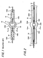
- FIG. 1 is a sectional view showing a short-arc type high pressure discharge lamp in related art
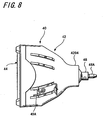
- FIG. 2 is a sectional view showing a manufacturing process of a short-arc type high pressure discharge lamp in related art
- FIGS. 3A through 3C are A-A line cross-sectional views of FIG. 2
- FIG. 4 is an enlarged view showing portions of an electrode axis and a sealed metal foil
- FIG. 5A is an enlarged view showing the portions of the electrode axis and sealed metal foil
- FIG. 5B is an enlarged view showing the inside of a circle in FIG. 5A .
- a short-arc type high pressure discharge lamp 10 includes: a discharge container 12 made of glass material such as quartz glass, a pair of electrodes 14, and two sealed metal foils 16.
- the discharge container 12 is formed of a pair of axis portions 1202 and a swelled portion 1204 provided between the pair of axis portions 1202 and having a sealed space 20 inside in which mercury and the like are enclosed.
- Each of electrodes 14 has an electrode axis 1402 and an electrode body 1404 provided at an end of the electrode axis 1402.
- the electrode axes 1402 are buried in the pair of axis portions 1202 respectively and the electrode bodies 1404 are disposed to face each other in the sealed space 20.
- Two sealed metal foils 16 extend like a strip having a narrow width and are buried in the axis portions 1202 such that the longitudinal direction thereof is parallel to the longitudinal direction of the axis portion 1202.
- the electrode axis 1402 is joined to one end in the longitudinal direction of the sealed metal foil 16 by resistance welding, and a lead wire 18 is joined to the other end in the longitudinal direction by the resistance welding.
- each of the pair of electrodes 14 to which the sealed metal foil 16 is welded is inserted respectively from each of small diameter portion 2202 of the glass tube 22 toward the large diameter portion 2204 to make the electrode bodies 1404 face each other in the large diameter portion 2204.
- the electrode axis portion 1402 welded to the sealed metal foil 16 is positioned in the small diameter portion 2202 as shown in FIGS. 2 and 3A .
- each small diameter portion 2202 positioned on the side opposite to the large diameter portion 2204 is irradiated with a laser light beam and is heated to fuse the end portions of the small diameter portions 2202 positioned around the lead wires 18 and so both ends of the glass tube 22 are sealed.
- the sealed space 20 hermetically sealed is formed inside the large diameter portion 2204.
- laser light beams are applied moving from the end portion of each small diameter portion 2202 toward the large diameter portion 2204 and so the whole area of the small diameter portion 2202 is sequentially heated.
- the portion of the small diameter portion 2202 around the lead wire 18 and the portion of the small diameter portion 2202 around the sealed metal foil 16 are fused.
- a barometric pressure inside the discharge container 12 is equal to or lower than the atmospheric pressure, because the large diameter portion 2204 is cooled down with the liquid nitrogen. Accordingly, as shown in FIG. 3B , the fused small diameter portion 2202 is shrunk to have a small outer diameter due to the difference in the pressure.
- the inner surface of the fused small diameter portion 2202 contacts with both ends in the widthwise direction of the sealed metal foil 16, the inner surface of the fused small diameter portion 2202 shrinks to come close toward the sealed metal foil 16 in the direction orthogonal to the widthwise direction of the sealed metal foil 16 as shown in FIG. 3C , because the sealed metal foil 16 serves as resistance. Then, the portion of the fused small diameter portion 2202 wraps the electrode axis 1402 and sealed metal foil 16 to be in a state where, as shown in FIG.
- gaps S are formed respectively.
- the gap S is continuous with the sealed space 20. Further, it is illustrated in FIG.
- FIG. 6A is a plan view showing portions of the electrode axis 1402 and the sealed metal foil 16 in an example of related art in which the shape of the sealed metal foil is changed; and FIG. 6B is a BB-line cross-sectional view of FIG. 6A . As shown in FIGS.
- the sealed metal foil 16 is wrapped up to a portion opposite to a portion welded to the sealed metal foil 16 along the outer circumferential surface 1402A of the electrode axis 1402 in the portion where the electrode axis 1402 is welded to the sealed metal foil 16 and so the gaps S formed on both sides of the electrode axis 1402 between the outer circumferential surface 1402A thereof and the surface 1602 of the sealed metal foil 16 are eliminated.
- Document EP 1 343 196 A in the cited prior art (see Fig. 6B and [0058]), shows a short-arc type high pressure discharge lamp with the pre-characterising features of claim 1, in particular gaps Y between the electrode shaft 7 and the foil 8 wrapped partially around it. In these gaps, the glass material of the seal does not enter.
- EP 1 308 987 A ( Fig.10 ).
- the sealed metal foil 16 is bent at the portion opposite to the portion welded to the sealed metal foil 16 and so this time V-shaped concave portions are formed respectively on both sides of the electrode axis 1402 at the bent portion on the rear surface 1604 of the sealed metal foil 16.
- the glass material portion 12A may not completely enter the respective concave portions and gaps S2 continuous with the sealed space 20 are formed, and since an acute angle ⁇ is formed by a surface 12-2 of the glass material portion 12A facing the gap S2 and the rear surface 1604 of the sealed metal foil 16 similarly to the above, there is a possibility that when the short-arc type high pressure discharge lamp 10 is lit, a crack may occur due to strong force that acts almost like a wedge along the boundary surface between the rear surface 1604 of the sealed metal foil 16 and the surface 12-2 of the glass material portion 12A similarly to the above.
- the present invention addresses the above-identified and other problems associated with conventional methods and apparatuses, and provides a short-arc type high pressure discharge lamp enabling durability to be improved and a lamp apparatus including the short-arc type high pressure discharge lamp.
- a short-arc type high pressure discharge lamp includes a discharge container made of glass material, a pair of electrodes, and two sealed metal foils electrically connected to the pair of electrodes respectively.
- the discharge container is formed of a pair of axis portions and a swelled portion provided between the pair of axis portions and having a sealed space inside.
- Each of electrodes includes an electrode axis and an electrode body provided at an end of the electrode axis, the electrode axes are buried in the pair of axis portions, and the electrode bodies are disposed to face each other in the sealed space.
- the sealed metal foil is in the shape of a strip having a narrow width and is formed to be buried together with the electrode axis in the axis portion, in a state where a middle portion in the widthwise direction at one end in the longitudinal direction of the sealed metal foil is made into a curved portion wrapping the outer circumferential surface of the electrode axis and the most depressed bottom portion of the curved portion is joined to a portion of the outer circumferential surface of the electrode axis contacting with the bottom portion, and the other end in the longitudinal direction of the sealed metal foil is connected to an outside power source. Glass material portions into which the glass material enters respectively are provided on both sides of the electrode axis between the outer circumferential surface thereof and the curved portion of the sealed metal foil.
- gaps continuous with the sealed space remain respectively among the glass material portion, the outer circumferential surface of the electrode axis, and the curved portion.
- the gap is formed to gradually narrow in the direction away from the glass material portion and along a circumferential direction of the electrode axis.
- the surface of the glass material portion facing the gap forms an obtuse angle with the curved portion.
- a lamp apparatus includes: a short-arc type high pressure discharge lamp as set out above, a protective tube that accommodates the short-arc type high pressure discharge lamp in a hermetically sealed state, an opening provided in the front portion of the protective tube, a transparent panel that hermetically closes the opening, a reflective surface provided on the inner surface of the protective tube to reflect light emitted from the short-arc type high pressure discharge lamp and to lead forward the light through the transparent panel, and a power-feed terminal provided on the outer surface of the protective tube and connected to an outside power source.
- the short-arc type high pressure discharge lamp includes: a discharge container made of glass material, a pair of electrodes, and two sealed metal foils electrically connected to the pair of electrodes, respectively.
- the discharge container is formed of a pair of axis portions and a swelled portion provided between the pair of axis portions and having a sealed space inside.
- Each of electrodes includes an electrode axis and an electrode body provided at an end of the electrode axis, the electrode axes are buried in the pair of axis portions, and the electrode bodies are disposed to face each other in the sealed space.
- the sealed metal foil is in the shape of a strip having a narrow width and is formed to be buried together with the electrode axis in the axis portion, in a state where a middle portion in the widthwise direction at one end in the longitudinal direction of the sealed metal foil is made into a curved portion wrapping the outer circumferential surface of the electrode axis and the most depressed bottom portion of the curved portion is joined to a portion of the outer circumferential surface of the electrode axis contacting with the bottom portion.
- the other end in the longitudinal direction of the sealed metal foil is connected to the power-feed terminal. Glass material portions into which the glass material enters respectively are provided on both sides of the electrode axis between the outer circumferential surface thereof and the curved portion of the sealed metal foil.
- gaps continuous with the sealed space remain respectively among the glass material portion, the outer circumferential surface of the electrode axis, and the curved portion.
- the gap is formed to be gradually small in the direction away from the glass material portion and along a circumferential direction of the electrode axis.
- the surface of the glass material portion facing the gap forms an obtuse angle with the curved portion.
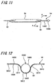
- the protective tube 40 includes a funnel-shaped body portion 42 made of hard glass having a parabolic reflective surface 4202 as an inner surface and a transparent panel 44 made of hard glass that hermetically seals a front opening of the body portion 42.
- One of axis portions 5202 of the short-arc type high pressure discharge lamp 50 is inserted into a neck portion 4204 of the body portion 42 from the inside of the body portion 42, and heat-resistant sealant 46 is filled in a gap formed between the outer circumferential surface of the axis portion 5202 and an inner circumferential surface of the neck portion 4204. Therefore, the short-arc type high pressure discharge lamp 50 is fixed airtightly to the neck portion 4204 of the body portion 42.
- one of the axis portion 5202 of the short-arc type high pressure discharge lamp 50 that protrudes outward from the neck portion 4202 is airtightly capped with a cap 48.
- a power-feed terminal 48A is provided for the cap 48, and one of a pair of lead wires 62 of the short-arc type high pressure discharge lamp 50 is connected to the power-feed terminal 48A.
- a power-feed terminal 49A is also provided on the outside surface of the body portion 42, and the other of the pair of lead wires 62 is connected to the power-feed terminal 49A through a lead conductor 49.
- the inside of the protective tube 40 is sealed with nitrogen gas so that heat of the short-arc type high pressure discharge lamp 50 is radiated excellently to the outside of the protective tube 40.
- the discharge container 52 is formed to have a pair of axis portions 5202 and a swelled portion 5204 provided between the pair of axis portions 5202 and having a sealed space 60 inside in which mercury and the like are filled.
- Each of the electrodes 54 has an electrode axis 5402 and an electrode body 5404 provided at an end of the electrode axis 5402, in which in this embodiment the pair of electrodes 54 are formed of tungsten and the diameter of the electrode axis 5402 is 0.3 mm.
- the electrode axes 5402 are buried in the pair of axis portions 5202 respectively, and the electrode bodies 5404 are disposed to face each other in the sealed space 60.
- glass material portions 52A into which glass material enters are provided respectively on both sides of the electrode axis 5402 between the outer circumferential surface 5406 thereof and the curved portion 58 of the sealed metal foil 56, and gaps S3 continuous with the sealed space 60 remain among the glass material portion 52A, the outer circumferential surface 5406 of the electrode axis 5402, and the curved portion 58.
- the gap S3 is formed to be gradually small in the direction away from the glass material portion 52A and along a circumferential direction of the electrode axis 5402.
- the surface 52-1 of the glass material portion 52A facing the gap S3 forms an obtuse angle ⁇ with the curved portion 58, in other words, an angle of a gap S3-1 formed at a portion where the surface 52-1 of the glass material portion 52A facing the gap S3 contacts with a surface 5602 of the curved portion 58 of the sealed metal foil 56 facing the gap S3 is an obtuse angle ⁇ .
- the lead wire 62 is joined to the other end in the longitudinal direction of the sealed metal foil 56 by resistance welding and is formed to be connected to an outside power source through the power-feed terminals 48A and 49A described above.
- two sealed metal foils 56 are made of molybdenum and the thickness thereof is 20 ⁇ m.
- the lead wire 62 is made of molybdenum and the diameter thereof is 0.4 mm.
- FIG. 13 is a sectional view showing a manufacturing process of a short-arc type high pressure discharge lamp according to a first embodiment
- FIGS. 14A through 14D are AA-line cross-sectional views of FIG. 13 .
- a glass tube 64 having a diameter larger than that of the axis portion 5202 of the discharge container 52 is prepared.
- the glass tube 64 includes a pair of small diameter portions 6402 having an inner diameter larger than the width of the sealed metal foil 56 and a large diameter portion 6404 having an inner diameter larger than the inner diameter of the small diameter portion 6402 and provided between the small diameter portions 6402.
- electrodes 54 are fixed to one end in the longitudinal direction of the pair of sealed metal foils 56, respectively.
- a middle portion (a center portion in this embodiment) in the widthwise direction at one end in the longitudinal direction of the sealed metal foil 56 is made into a semi-cylindrical portion 5812 wrapping half the outer circumferential surface 5406 of the electrode axis 5402 (in other words, the semi-cylindrical portion 5812 whose inner radius is equal to the outer circumferential surface 5406 of the electrode axis 5402), and the most depressed bottom portion 5802 of the semi-cylindrical portion 5812 is joined by resistance welding to the portion of the outer circumferential surface 5406 of the electrode axis 5402 contacting with the bottom portion 5802.
- the semi-cylindrical portion 5812 and cylindrical surface portions 5814 on both sides constitutes the curved portion 58 wrapping the outer circumferential surface 5406 of the electrode axis 5402, provided in the middle portion in the widthwise direction at one end in the longitudinal direction of the sealed metal foil 56.
- a virtual line connecting the flat portions 5612 on both sides passes at the upper end of the outer circumferential surface 5406 positioned opposite to the bottom portion 5802 and therefore the cylindrical surface portion 5814 is a convex-shaped cylindrical surface toward the upper end of the outer circumferential surface 5406 positioned opposite to the bottom portion 5802, and the depth of the curved portion 58 from the flat portions 5612 on both sides is almost equal to the diameter of the electrode axis 5402.
- the end portions of the small diameter portions 6402 positioned on the opposite side to the large diameter portion 6404 are irradiated with laser light beams and are heated, and so the edge portion of each small diameter portion 6402 positioned around the lead wire 62 is fused to seal both the ends of the glass tube 64.
- the hermetically sealed space 60 is formed inside the large diameter portion 6404.
- liquid nitrogen is applied to the large diameter portion 6404 to cool mercury in the sealed space 60 not to evaporate and the whole area of the small diameter portion 6402 is irradiated with the laser light beam to be heated sequentially by moving the light beam from the edge portion of each small diameter portion 6402 toward the large diameter portion 6404.
Landscapes
- Engineering & Computer Science (AREA)
- Manufacturing & Machinery (AREA)
- Vessels And Coating Films For Discharge Lamps (AREA)
- Non-Portable Lighting Devices Or Systems Thereof (AREA)
Claims (4)
- Lampe à décharge haute pression du type à arc court (50) comprenant :- un contenant de décharge (52) réalisé en verre,- une paire d'électrodes (54), et- deux feuilles de métal scellées (56) connectées électriquement à ladite paire d'électrodes (54), respectivement,
dans laquelle- ledit contenant de décharge (52) consiste en une paire de parties axiales (5202) et une partie renflée (5204) prévue entre ladite paire de parties axiales (5202) et comportant un espace étanche (60) à l'intérieur ;- chacune de ladite paire d'électrodes (54) comprend un axe d'électrode (5402) et un corps d'électrode (5404) prévu à une extrémité dudit axe d'électrode (5402), les axes d'électrode (5402) sont enfouis dans ladite paire de parties axiales (5202), et les corps d'électrode (5404) sont disposés de manière à se faire face dans ledit espace étanche (60) ;- ladite feuille métallique scellée (56) à la forme d'une bande et est enfouie avec ledit axe d'électrode (5402) dans ladite partie axiale (5202), dans un état dans lequel une partie centrale dans le sens de la largeur à une extrémité dans la direction longitudinale de ladite feuille métallique scellée (56) est réalisée en une partie incurvée (58) enveloppant la surface circonférentielle externe (5406) dudit axe d'électrode (5402) et la partie inférieure la plus basse (5802) de ladite partie incurvée (58) est jointe à une partie de la surface circonférentielle externe (5406) dudit axe d'électrode (5402), et l'autre extrémité dans la direction longitudinale de ladite feuille métallique scellée (56) est formée de manière à être connectée à une source de puissance extérieure ;- des parties en verre (52A) formées par l'écoulement dudit verre entre la surface circonférentielle externe (5406) dudit axe d'électrode (5402) et la partie incurvée (58) de ladite feuille métallique scellée (56), où- des espaces (S3) dans le prolongement dudit espace étanche (60) subsistent parmi ladite partie en verre (52A), la surface circonférentielle externe (5406) dudit axe d'électrode (5402) et ladite partie incurvée (58) ;- ledit espace (S3) est formé de manière à diminuer graduellement dans la direction d'éloignement de ladite partie en verre (52A) et le long de la direction circonférentielle dudit axe d'électrode (5402),
caractérisée en ce que- la surface (52-1) de ladite partie en verre (52A) faisant face audit espace (S3) forme un angle obtus (Φ) avec ladite partie incurvée (58). - Lampe à décharge haute pression du type à arc court (50) selon la revendication 1,
dans laquelle ladite partie incurvée (58) comprend :- une partie semi-cylindrique (5812) dont le rayon interne est égal à celui dudit axe d'électrode (5402) et qui enveloppe une moitié de la surface circonférentielle externe (5406) dudit axe d'électrode (5402), et- des parties de surface (5814), formées de manière à s'éloigner graduellement d'une extrémité supérieure de ladite partie semi-cylindrique (5812) le long d'une surface cylindrique, lesdites parties de surface (5814) étant reliées de manière continue aux extrémités supérieures de ladite partie semi-cylindrique (5812) des deux côtés et aux parties plates (5612) des deux côtés subsistant des deux côtés dans le sens de la largeur de ladite feuille métallique scellée (56) et ledit angle (Φ) formé par la surface de ladite partie en verre (52A) faisant face audit espace (S3) et ladite partie incurvée (58) étant l'angle formé par la surface de ladite partie en verre (52A) faisant face audit espace (S3) et lesdites parties de surface (5814). - Lampe à décharge haute pression du type à arc court selon la revendication 2,
dans laquelle la profondeur de ladite partie incurvée (58), entre ladite partie inférieure la plus basse (5802) et une ligne virtuelle reliant les parties plates (5612), est pratiquement égale au diamètre dudit axe d'électrode (5402). - Dispositif de lampe (30) comprenant :une lampe à décharge haute pression du type à arc court (50) selon l'une des revendications 1 à 3,- un tube de protection (40) qui loge ladite lampe à décharge haute pression du type à arc court (50) dans l'état scellé,- une ouverture prévue dans la partie avant dudit tube de protection (40),- un panneau transparent (44) qui ferme ladite ouverture hermétiquement, et- une surface réfléchissante (4202) prévue sur la surface interne dudit tube de protection (40) pour réfléchir la lumière émise par ladite lampe à décharge haute pression du type à arc court (50) et pour conduire la lumière vers l'avant à travers ledit panneau transparent (44), et- une borne d'alimentation (48A) prévue sur la surface externe dudit tube de protection (40) et formée pour être connectée à une source de puissance extérieure.
Applications Claiming Priority (1)
| Application Number | Priority Date | Filing Date | Title |
|---|---|---|---|
| JP2005103540A JP4171475B2 (ja) | 2005-03-31 | 2005-03-31 | ショートアーク型高圧放電ランプおよびランプ装置 |
Publications (3)
| Publication Number | Publication Date |
|---|---|
| EP1708246A2 EP1708246A2 (fr) | 2006-10-04 |
| EP1708246A3 EP1708246A3 (fr) | 2008-02-13 |
| EP1708246B1 true EP1708246B1 (fr) | 2010-09-15 |
Family
ID=36675878
Family Applications (1)
| Application Number | Title | Priority Date | Filing Date |
|---|---|---|---|
| EP06006738A Expired - Lifetime EP1708246B1 (fr) | 2005-03-31 | 2006-03-30 | Lampe à dècharge à arc court et système d'illumination |
Country Status (6)
| Country | Link |
|---|---|
| US (1) | US7635950B2 (fr) |
| EP (1) | EP1708246B1 (fr) |
| JP (1) | JP4171475B2 (fr) |
| KR (1) | KR101215803B1 (fr) |
| CN (1) | CN1873903B (fr) |
| DE (1) | DE602006016888D1 (fr) |
Families Citing this family (3)
| Publication number | Priority date | Publication date | Assignee | Title |
|---|---|---|---|---|
| JP4887916B2 (ja) * | 2006-06-08 | 2012-02-29 | ウシオ電機株式会社 | 放電ランプおよび放電ランプ用の金属箔 |
| CN101506930B (zh) * | 2006-08-23 | 2011-11-16 | 松下电器产业株式会社 | 高压放电灯的制造方法、高压放电灯、灯单元以及投影型图像显示装置 |
| JP6295776B2 (ja) * | 2014-03-28 | 2018-03-20 | 東芝ライテック株式会社 | 放電ランプ、および放電ランプの製造方法 |
Family Cites Families (8)
| Publication number | Priority date | Publication date | Assignee | Title |
|---|---|---|---|---|
| DE19729219B4 (de) | 1997-07-09 | 2004-02-19 | Patent-Treuhand-Gesellschaft für elektrische Glühlampen mbH | Hochdruckentladungslampe mit gekühlter Elektrode sowie entsprechende Elektrode |
| JP2001176302A (ja) * | 1999-12-16 | 2001-06-29 | Ushio Inc | 光学装置 |
| JP3596448B2 (ja) | 2000-09-08 | 2004-12-02 | ウシオ電機株式会社 | ショートアーク型水銀放電ランプ |
| JP3664972B2 (ja) | 2000-12-05 | 2005-06-29 | 株式会社小糸製作所 | アークチューブ |
| JP2003051210A (ja) | 2001-07-24 | 2003-02-21 | Three M Innovative Properties Co | 可溶性ポリイミドを用いたリフレクタ、それを備える放電ランプ及び画像投影装置 |
| JP3518533B2 (ja) | 2001-10-19 | 2004-04-12 | ウシオ電機株式会社 | ショートアーク型超高圧放電ランプ |
| JP3570414B2 (ja) | 2002-03-05 | 2004-09-29 | ウシオ電機株式会社 | ショートアーク型超高圧放電ランプ |
| EP1623446A2 (fr) | 2003-05-01 | 2006-02-08 | Koninklijke Philips Electronics N.V. | Procede pour fabriquer une lampe |
-
2005
- 2005-03-31 JP JP2005103540A patent/JP4171475B2/ja not_active Expired - Lifetime
-
2006
- 2006-03-29 US US11/391,175 patent/US7635950B2/en active Active
- 2006-03-30 EP EP06006738A patent/EP1708246B1/fr not_active Expired - Lifetime
- 2006-03-30 DE DE602006016888T patent/DE602006016888D1/de not_active Expired - Lifetime
- 2006-03-30 KR KR1020060028710A patent/KR101215803B1/ko not_active Expired - Lifetime
- 2006-03-31 CN CN2006100820190A patent/CN1873903B/zh not_active Expired - Lifetime
Also Published As
| Publication number | Publication date |
|---|---|
| CN1873903B (zh) | 2010-07-07 |
| KR101215803B1 (ko) | 2012-12-26 |
| US7635950B2 (en) | 2009-12-22 |
| EP1708246A3 (fr) | 2008-02-13 |
| US20070013288A1 (en) | 2007-01-18 |
| EP1708246A2 (fr) | 2006-10-04 |
| JP2006286350A (ja) | 2006-10-19 |
| JP4171475B2 (ja) | 2008-10-22 |
| DE602006016888D1 (de) | 2010-10-28 |
| KR20060105536A (ko) | 2006-10-11 |
| CN1873903A (zh) | 2006-12-06 |
Similar Documents
| Publication | Publication Date | Title |
|---|---|---|
| CN1257531C (zh) | 高气压放电灯 | |
| TWI415163B (zh) | 氣體放電燈及其製造方法 | |
| EP0866488B1 (fr) | Procédé de fabrication d'une lampe à décharge à haute pression | |
| KR100247669B1 (ko) | 전기 램프 | |
| JPH06124690A (ja) | 高圧放電ランプ | |
| US6452334B1 (en) | Arc tube with residual-compressive-stress layer for discharge lamp unit and method of manufacturing same | |
| EP0645800A1 (fr) | Lampe à décharge haute pression | |
| EP1708246B1 (fr) | Lampe à dècharge à arc court et système d'illumination | |
| US6411037B1 (en) | Arc tube for discharge lamp device and method of manufacturing the same | |
| JP5418886B2 (ja) | 放電ランプおよびその製造方法 | |
| JPH06103961A (ja) | 添加用カプセルをそなえたアーク放電ランプ | |
| US5440196A (en) | Dual-envelope high-pressure discharge lamp construction, and method of its manufacture | |
| US20070114942A1 (en) | Discharge lamp | |
| JP2858124B2 (ja) | アーク放電管のためのアーク管 | |
| JP3217313B2 (ja) | 高圧放電ランプおよびその製造方法 | |
| JP3789279B2 (ja) | 高圧放電灯 | |
| JPH05174704A (ja) | 放電管 | |
| JPH0537400Y2 (fr) | ||
| EP3039706B1 (fr) | Lampe à décharge de gaz électrique avec antenne active couplée à la décharge | |
| JP7505263B2 (ja) | ショートアーク型放電ランプ | |
| JP7141692B2 (ja) | 放電灯の封止構造、および当該構造を備える放電灯 | |
| JPH0350609Y2 (fr) | ||
| JPH08329895A (ja) | 金属蒸気発光管の封止構造 | |
| JP2007184130A (ja) | 自動車用放電ランプ | |
| JPH05325899A (ja) | 管 球 |
Legal Events
| Date | Code | Title | Description |
|---|---|---|---|
| PUAI | Public reference made under article 153(3) epc to a published international application that has entered the european phase |
Free format text: ORIGINAL CODE: 0009012 |
|
| AK | Designated contracting states |
Kind code of ref document: A2 Designated state(s): AT BE BG CH CY CZ DE DK EE ES FI FR GB GR HU IE IS IT LI LT LU LV MC NL PL PT RO SE SI SK TR |
|
| AX | Request for extension of the european patent |
Extension state: AL BA HR MK YU |
|
| PUAL | Search report despatched |
Free format text: ORIGINAL CODE: 0009013 |
|
| AK | Designated contracting states |
Kind code of ref document: A3 Designated state(s): AT BE BG CH CY CZ DE DK EE ES FI FR GB GR HU IE IS IT LI LT LU LV MC NL PL PT RO SE SI SK TR |
|
| AX | Request for extension of the european patent |
Extension state: AL BA HR MK YU |
|
| 17P | Request for examination filed |
Effective date: 20080612 |
|
| 17Q | First examination report despatched |
Effective date: 20080715 |
|
| AKX | Designation fees paid |
Designated state(s): DE NL |
|
| GRAP | Despatch of communication of intention to grant a patent |
Free format text: ORIGINAL CODE: EPIDOSNIGR1 |
|
| GRAS | Grant fee paid |
Free format text: ORIGINAL CODE: EPIDOSNIGR3 |
|
| GRAA | (expected) grant |
Free format text: ORIGINAL CODE: 0009210 |
|
| AK | Designated contracting states |
Kind code of ref document: B1 Designated state(s): DE NL |
|
| REF | Corresponds to: |
Ref document number: 602006016888 Country of ref document: DE Date of ref document: 20101028 Kind code of ref document: P |
|
| REG | Reference to a national code |
Ref country code: NL Ref legal event code: T3 |
|
| PLBE | No opposition filed within time limit |
Free format text: ORIGINAL CODE: 0009261 |
|
| STAA | Information on the status of an ep patent application or granted ep patent |
Free format text: STATUS: NO OPPOSITION FILED WITHIN TIME LIMIT |
|
| 26N | No opposition filed |
Effective date: 20110616 |
|
| REG | Reference to a national code |
Ref country code: DE Ref legal event code: R097 Ref document number: 602006016888 Country of ref document: DE Effective date: 20110616 |
|
| REG | Reference to a national code |
Ref country code: DE Ref legal event code: R082 Ref document number: 602006016888 Country of ref document: DE Representative=s name: DENNEMEYER & ASSOCIATES S.A., DE Ref country code: DE Ref legal event code: R081 Ref document number: 602006016888 Country of ref document: DE Owner name: ORC MANUFACTURING CO., LTD., MACHIDA, JP Free format text: FORMER OWNERS: ORC MANUFACTURING CO., LTD., MACHIDA, TOKYO, JP; SONY CORPORATION, TOKIO/TOKYO, JP |
|
| REG | Reference to a national code |
Ref country code: NL Ref legal event code: PD Owner name: ORC MANUFACTURING CO., LTD.; JP Free format text: DETAILS ASSIGNMENT: CHANGE OF OWNER(S), ASSIGNMENT; FORMER OWNER NAME: SONY CORPORATION Effective date: 20200903 |
|
| PGFP | Annual fee paid to national office [announced via postgrant information from national office to epo] |
Ref country code: DE Payment date: 20250319 Year of fee payment: 20 |
|
| PGFP | Annual fee paid to national office [announced via postgrant information from national office to epo] |
Ref country code: NL Payment date: 20250319 Year of fee payment: 20 |
|
| REG | Reference to a national code |
Ref country code: DE Ref legal event code: R082 Ref document number: 602006016888 Country of ref document: DE Representative=s name: DENNEMEYER & ASSOCIATES RECHTSANWALTSGESELLSCH, DE |
|
| REG | Reference to a national code |
Ref country code: DE Ref legal event code: R071 Ref document number: 602006016888 Country of ref document: DE |
|
| REG | Reference to a national code |
Ref country code: NL Ref legal event code: MK Effective date: 20260329 |