EP1709228B1 - Fasermatte und verfahren zur herstellung einer fasermatte - Google Patents
Fasermatte und verfahren zur herstellung einer fasermatte Download PDFInfo
- Publication number
- EP1709228B1 EP1709228B1 EP05700569A EP05700569A EP1709228B1 EP 1709228 B1 EP1709228 B1 EP 1709228B1 EP 05700569 A EP05700569 A EP 05700569A EP 05700569 A EP05700569 A EP 05700569A EP 1709228 B1 EP1709228 B1 EP 1709228B1
- Authority
- EP
- European Patent Office
- Prior art keywords
- batches
- fibres
- carrier layer
- conveyed
- threads
- Prior art date
- Legal status (The legal status is an assumption and is not a legal conclusion. Google has not performed a legal analysis and makes no representation as to the accuracy of the status listed.)
- Expired - Lifetime
Links
Images



Classifications
-
- D—TEXTILES; PAPER
- D04—BRAIDING; LACE-MAKING; KNITTING; TRIMMINGS; NON-WOVEN FABRICS
- D04H—MAKING TEXTILE FABRICS, e.g. FROM FIBRES OR FILAMENTARY MATERIAL; FABRICS MADE BY SUCH PROCESSES OR APPARATUS, e.g. FELTS, NON-WOVEN FABRICS; COTTON-WOOL; WADDING ; NON-WOVEN FABRICS FROM STAPLE FIBRES, FILAMENTS OR YARNS, BONDED WITH AT LEAST ONE WEB-LIKE MATERIAL DURING THEIR CONSOLIDATION
- D04H1/00—Non-woven fabrics formed wholly or mainly of staple fibres or like relatively short fibres
- D04H1/40—Non-woven fabrics formed wholly or mainly of staple fibres or like relatively short fibres from fleeces or layers composed of fibres without existing or potential cohesive properties
- D04H1/44—Non-woven fabrics formed wholly or mainly of staple fibres or like relatively short fibres from fleeces or layers composed of fibres without existing or potential cohesive properties the fleeces or layers being consolidated by mechanical means, e.g. by rolling
-
- B—PERFORMING OPERATIONS; TRANSPORTING
- B29—WORKING OF PLASTICS; WORKING OF SUBSTANCES IN A PLASTIC STATE IN GENERAL
- B29C—SHAPING OR JOINING OF PLASTICS; SHAPING OF MATERIAL IN A PLASTIC STATE, NOT OTHERWISE PROVIDED FOR; AFTER-TREATMENT OF THE SHAPED PRODUCTS, e.g. REPAIRING
- B29C70/00—Shaping composites, i.e. plastics material comprising reinforcements, fillers or preformed parts, e.g. inserts
- B29C70/04—Shaping composites, i.e. plastics material comprising reinforcements, fillers or preformed parts, e.g. inserts comprising reinforcements only, e.g. self-reinforcing plastics
- B29C70/06—Fibrous reinforcements only
- B29C70/10—Fibrous reinforcements only characterised by the structure of fibrous reinforcements, e.g. hollow fibres
- B29C70/16—Fibrous reinforcements only characterised by the structure of fibrous reinforcements, e.g. hollow fibres using fibres of substantial or continuous length
- B29C70/22—Fibrous reinforcements only characterised by the structure of fibrous reinforcements, e.g. hollow fibres using fibres of substantial or continuous length oriented in at least two directions forming a two-dimensional [2D] structure
- B29C70/226—Fibrous reinforcements only characterised by the structure of fibrous reinforcements, e.g. hollow fibres using fibres of substantial or continuous length oriented in at least two directions forming a two-dimensional [2D] structure the structure comprising mainly parallel filaments interconnected by a small number of cross threads
-
- D—TEXTILES; PAPER
- D04—BRAIDING; LACE-MAKING; KNITTING; TRIMMINGS; NON-WOVEN FABRICS
- D04B—KNITTING
- D04B21/00—Warp knitting processes for the production of fabrics or articles not dependent on the use of particular machines; Fabrics or articles defined by such processes
- D04B21/14—Fabrics characterised by the incorporation by knitting, in one or more thread, fleece, or fabric layers, of reinforcing, binding, or decorative threads; Fabrics incorporating small auxiliary elements, e.g. for decorative purposes
- D04B21/16—Fabrics characterised by the incorporation by knitting, in one or more thread, fleece, or fabric layers, of reinforcing, binding, or decorative threads; Fabrics incorporating small auxiliary elements, e.g. for decorative purposes incorporating synthetic threads
- D04B21/165—Fabrics characterised by the incorporation by knitting, in one or more thread, fleece, or fabric layers, of reinforcing, binding, or decorative threads; Fabrics incorporating small auxiliary elements, e.g. for decorative purposes incorporating synthetic threads with yarns stitched through one or more layers or tows, e.g. stitch-bonded fabrics
-
- D—TEXTILES; PAPER
- D04—BRAIDING; LACE-MAKING; KNITTING; TRIMMINGS; NON-WOVEN FABRICS
- D04H—MAKING TEXTILE FABRICS, e.g. FROM FIBRES OR FILAMENTARY MATERIAL; FABRICS MADE BY SUCH PROCESSES OR APPARATUS, e.g. FELTS, NON-WOVEN FABRICS; COTTON-WOOL; WADDING ; NON-WOVEN FABRICS FROM STAPLE FIBRES, FILAMENTS OR YARNS, BONDED WITH AT LEAST ONE WEB-LIKE MATERIAL DURING THEIR CONSOLIDATION
- D04H1/00—Non-woven fabrics formed wholly or mainly of staple fibres or like relatively short fibres
- D04H1/40—Non-woven fabrics formed wholly or mainly of staple fibres or like relatively short fibres from fleeces or layers composed of fibres without existing or potential cohesive properties
- D04H1/42—Non-woven fabrics formed wholly or mainly of staple fibres or like relatively short fibres from fleeces or layers composed of fibres without existing or potential cohesive properties characterised by the use of certain kinds of fibres insofar as this use has no preponderant influence on the consolidation of the fleece
- D04H1/4209—Inorganic fibres
- D04H1/4218—Glass fibres
-
- D—TEXTILES; PAPER
- D04—BRAIDING; LACE-MAKING; KNITTING; TRIMMINGS; NON-WOVEN FABRICS
- D04H—MAKING TEXTILE FABRICS, e.g. FROM FIBRES OR FILAMENTARY MATERIAL; FABRICS MADE BY SUCH PROCESSES OR APPARATUS, e.g. FELTS, NON-WOVEN FABRICS; COTTON-WOOL; WADDING ; NON-WOVEN FABRICS FROM STAPLE FIBRES, FILAMENTS OR YARNS, BONDED WITH AT LEAST ONE WEB-LIKE MATERIAL DURING THEIR CONSOLIDATION
- D04H1/00—Non-woven fabrics formed wholly or mainly of staple fibres or like relatively short fibres
- D04H1/40—Non-woven fabrics formed wholly or mainly of staple fibres or like relatively short fibres from fleeces or layers composed of fibres without existing or potential cohesive properties
- D04H1/42—Non-woven fabrics formed wholly or mainly of staple fibres or like relatively short fibres from fleeces or layers composed of fibres without existing or potential cohesive properties characterised by the use of certain kinds of fibres insofar as this use has no preponderant influence on the consolidation of the fleece
- D04H1/4209—Inorganic fibres
- D04H1/4242—Carbon fibres
-
- D—TEXTILES; PAPER
- D04—BRAIDING; LACE-MAKING; KNITTING; TRIMMINGS; NON-WOVEN FABRICS
- D04H—MAKING TEXTILE FABRICS, e.g. FROM FIBRES OR FILAMENTARY MATERIAL; FABRICS MADE BY SUCH PROCESSES OR APPARATUS, e.g. FELTS, NON-WOVEN FABRICS; COTTON-WOOL; WADDING ; NON-WOVEN FABRICS FROM STAPLE FIBRES, FILAMENTS OR YARNS, BONDED WITH AT LEAST ONE WEB-LIKE MATERIAL DURING THEIR CONSOLIDATION
- D04H13/00—Other non-woven fabrics
-
- D—TEXTILES; PAPER
- D04—BRAIDING; LACE-MAKING; KNITTING; TRIMMINGS; NON-WOVEN FABRICS
- D04H—MAKING TEXTILE FABRICS, e.g. FROM FIBRES OR FILAMENTARY MATERIAL; FABRICS MADE BY SUCH PROCESSES OR APPARATUS, e.g. FELTS, NON-WOVEN FABRICS; COTTON-WOOL; WADDING ; NON-WOVEN FABRICS FROM STAPLE FIBRES, FILAMENTS OR YARNS, BONDED WITH AT LEAST ONE WEB-LIKE MATERIAL DURING THEIR CONSOLIDATION
- D04H3/00—Non-woven fabrics formed wholly or mainly of yarns or like filamentary material of substantial length
- D04H3/08—Non-woven fabrics formed wholly or mainly of yarns or like filamentary material of substantial length characterised by the method of strengthening or consolidating
- D04H3/10—Non-woven fabrics formed wholly or mainly of yarns or like filamentary material of substantial length characterised by the method of strengthening or consolidating with bonds between yarns or filaments made mechanically
-
- D—TEXTILES; PAPER
- D10—INDEXING SCHEME ASSOCIATED WITH SUBLASSES OF SECTION D, RELATING TO TEXTILES
- D10B—INDEXING SCHEME ASSOCIATED WITH SUBLASSES OF SECTION D, RELATING TO TEXTILES
- D10B2403/00—Details of fabric structure established in the fabric forming process
- D10B2403/02—Cross-sectional features
- D10B2403/024—Fabric incorporating additional compounds
- D10B2403/0241—Fabric incorporating additional compounds enhancing mechanical properties
- D10B2403/02411—Fabric incorporating additional compounds enhancing mechanical properties with a single array of unbent yarn, e.g. unidirectional reinforcement fabrics
-
- D—TEXTILES; PAPER
- D10—INDEXING SCHEME ASSOCIATED WITH SUBLASSES OF SECTION D, RELATING TO TEXTILES
- D10B—INDEXING SCHEME ASSOCIATED WITH SUBLASSES OF SECTION D, RELATING TO TEXTILES
- D10B2505/00—Industrial
- D10B2505/02—Reinforcing materials; Prepregs
-
- Y—GENERAL TAGGING OF NEW TECHNOLOGICAL DEVELOPMENTS; GENERAL TAGGING OF CROSS-SECTIONAL TECHNOLOGIES SPANNING OVER SEVERAL SECTIONS OF THE IPC; TECHNICAL SUBJECTS COVERED BY FORMER USPC CROSS-REFERENCE ART COLLECTIONS [XRACs] AND DIGESTS
- Y10—TECHNICAL SUBJECTS COVERED BY FORMER USPC
- Y10T—TECHNICAL SUBJECTS COVERED BY FORMER US CLASSIFICATION
- Y10T428/00—Stock material or miscellaneous articles
- Y10T428/24—Structurally defined web or sheet [e.g., overall dimension, etc.]
- Y10T428/24033—Structurally defined web or sheet [e.g., overall dimension, etc.] including stitching and discrete fastener[s], coating or bond
Definitions
- the invention relates to a method of manufacturing a fibre mat adapted for use in the manufacture of a fibre-reinforced device, said fibre mat comprising at least two essentially longitudinally extending and parallel batches of fibres optionally in combination with one or more carrier layers and holder means such as thread or the like.
- the invention further relates to a fibre mat and use of a fibre mat.
- fibre mats consisting of unidirectional batches of fibres for constructing laminates for various fibre-reinforced plastics objects, including ia large objects, eg blades for wind energy plants, for use in the boat industry, the airplane industry, the car industry or for structural elements.
- the batches may be secured to subjacent layers of other batches or to a carrier layer of felt by means of stitching by the so-called "Tricot stitching".
- Tricot stitching In popular terms that kind of stitching is described as a zigzag stitching performed with a thread across each of the individual batches of the mat.
- tricot-stitch stitching is associated with the drawback that the fibres are influenced by the stitching and assume a sinus curve-like shape in the longitudinal direction of the fibres with a "swing" for the attachment of each thread to the carrier layer, which is due to pull forces in the thread.
- the effect is that the batches can be compressed to be flat which may result in a protracted and impaired moulding process, as the distribution of resin becomes harder, since the compressed batches may have a blocking effect on the transport of resin in the direction of thickness of the laminate.
- the moulding technique used is the VARTM process (Vacuum Assisted Resin Transfer Moulding).
- VARTM process Vauum Assisted Resin Transfer Moulding
- Novel aspects of the method according to the invention involves that the method comprises joining of the batches by holder means that span each batch at an angle in such a manner that the holder means influence each batch essentially symmetrically about an axis situated longitudinally between the batches.
- Symmetrical influence about an axis longitudinally between the batches means that influence from one side is matched by an influence from an opposite side.
- the batch will undulate; however, due to the symmetrical influence it may be powerful enough to fixate the batch to the effect that it is not compressed to be flat during moulding.
- the batches remain clearly separated, whereby resin is more readily conveyed longitudinally, transversally and in depth relative to the batches. Without the undulations, the batches are straight and straightened and hence have superior properties in compression.
- the holder means may comprise at least one thread which is conveyed in a predetermined pattern above or below, respectively, each of the batches.
- the method can be exercised in prior art plants for manufacturing fibre mats, where the manufacturing process comprises stitching.
- the thread can be configured transversally to the batches in a direction which is essentially perpendicular to the longitudinal direction of the batches.
- the influence on the thread on the batches becomes symmetrical about an axis between the batches.
- At least one thread can be conveyed in a pattern that comprises cross-stitches.
- the cross-stitches can be performed to be symmetrical and hence undo each other's influence on the batches.
- the at least one thread is conveyed in a pattern that comprises stitches that are arranged longitudinally between the batches.
- the fibre mat further comprises at least a first carrier layer onto which the batches are secured by the holder means.
- the carrier layer assists in keeping the batches together.
- the drapeability of the joined batches is maintained, while simultaneously the above-referenced advantages are maintained.
- production-technical advantages are accomplished since, when using a subjacent carrier layer, it is necessary to only to make the holder means cross the batches on the top face and not on the bottom face.
- the thread can be conveyed in stitches that have a length corresponding to one through ten times the width of a neighbouring batch.
- suitable length is imparted to the stitches and hence also distance between the securing points of the batches onto the carrier layer. Too close stitches will mean that unnecessarily much thread will be used, while too long stitches will mean imprecise securing of the batches.
- a further preferred embodiment may comprise that means are provided for handling a number of threads and means for handling a carrier layer and a number of batches of fibres, and wherein the majority of the batches are secured by the steps of:
- a further preferred embodiment may comprise that means are provided for handling a number of threads and means for handling a carrier layer and a number of fibre batches, and wherein the majority of the batches are secured in the steps of:
- the holder means may comprise a second carrier layer that is secured to the first carrier layer by at least three joints or rows of joints extending in parallel, whereby the first and the second carrier layer with the joints form a number of ducts in which the batches are arranged.
- the first and the second carrier layer may cooperate for precise enclosure of the batches of fibres that are hence not allowed to undulate. Moreover it is ensured that resin can easily be conveyed in the area between two neighbouring ducts.
- the joints or rows of joints can be formed by a process selected from a group comprising stitching, gluing and welding. These processes are easy to exercise and simultaneously provide reliable functioning.
- the joints are made in rows, there may be distance between joints longitudinally of the batches, whereby resin is also allowed to be more easily conveyed transversally of the batches between the joints.
- the first carrier layer may be selected from a group comprising a material which is permeable to resin, including in the form of fibres disposed diagonally or transversely relative to batches of fibres, a non-woven material, braided fibres and woven fibres, including glass fibres.
- the threads can be conveyed with a tensile force which is adapted such that a rounded contour is imparted to the batches in the transverse direction.
- a tensile force which is adapted such that a rounded contour is imparted to the batches in the transverse direction.
- the amount of fibres in the batches can be adapted in relation to the size of the ducts whereby a rounded contour is imparted to the batches in the transverse direction.
- a rounded contour is imparted to the batches in the transverse direction.
- the batches may comprise fibres selected from a group comprising glass fibres, carbon fibres, fibres that have less electrical resistance than glass fibres, and combinations of fibres of various materials.
- Novel aspects of a fibre mat according to the invention involves that it is adapted for use in the manufacture of a fibre-reinforced device and comprises at least two essentially longitudinally extending and parallel batches of fibres, wherein the batches are joined by holder means that span each batch at an angle to the effect that each batch is influenced, which influence is essentially symmetrical about an axis situated longitudinally between the batches.
- a symmetrical influence about an axis longitudinally between the bathes accomplishes that a influence from one side is matched by an influence from an opposite side.
- the batches will undulate.
- the batches can be fixated tightly so as to prevent them from being compressed to be flat during moulding. Simultaneously the batches are clearly separated, whereby resin is more easily conducted in the transverse direction, longitudinally and in depth of the batches. Without the undulations the batches are straight and straightened and hence have superior properties in compression.
- a fibre mat according to one or more of claims 16-26 can advantageously be used in RTM moulding of a fibre-reinforced device or VARTM, hand laying or prepeg (wet or dry), respectively. Precisely by a VARTM moulding the improved property with regard to conductivity is particularly advantageous.
- the above-reference fibre mats can be used in the moulding of a device which is configured to partake in a blade for a wind energy plant, including eg a blade shell or a reinforcing beam.
- a blade for a wind energy plant including eg a blade shell or a reinforcing beam.
- Such blades have very great length and a portion of fibres is often arranged so as to extend throughout the entire blade length.
- the improved property with regard to conductivity of resin is particularly advantageous.
- the improved properties in compression have great value, since both sides of a blade can be exposed to large loads that entail compression.
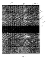
- Figure 1 shows a fibre mat 1 comprising a number of batches of fibres 2 that are secured to a non-visible carrier layer 3.
- Holder means in the form of threads 6 and 11 keep the batches securely attached to the non-visible carrier layer.
- Threads 6 and 11 are conveyed in a manner to comprise cross-stitches 10 and straight stitches 9 that are arranged in parallel with batches 2.
- Stitches 10 influence the batches 2 symmetrically about an axis 5 longitudinally between the batches as taught in the figure.
- Each batch 2 has a width B, but may also have other widths and, likewise, there may be different types of fibres from one batch to another and within individual batches. Thus there may be batches that comprise glass fibres and carbon fibres admixed in a fixed ratio.
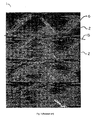
- Figure 2 shows a fibre mat 1 comprising a number of batches of fibres 2 that are secured to a non-visible carrier layer 3.
- Holder means in the form of threads 6 and 11 keep the batches 2 securely to the non-visible carrier layer.
- Threads 6 and 11 are conveyed in a manner that comprises cross-stitches 10. The stitches influence the batches 2 symmetrically about a non-shown axis longitudinally between the batches, thereby avoiding that the batches 2 undulate. A corresponding axis of symmetry will appear from Figure 1 . Between batches 2, individual loops 14 will appear that fixate the stitches 10.
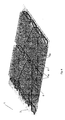
- Figure 3 shows a prior art fibre mat 1 with batches 2 of fibres.
- the batches 2 are fixated by tricot-stitches that extend in a zigzag-like pattern and not symmetrical about any axis longitudinally of the batches.
- An incorporated curve 15 underlines how the batches 2 wind, which is, as mentioned previously, undesired.
- Figure 4 shows a fibre mat 1 that comprises a carrier layer 3 which is merely outlined and depicted transparently. Batches of fibres are not shown. Threads 6 and 11 are conveyed in a manner that comprises cross-stitches 10. Moreover, the Figure shows that the threads 6, 11 are pulled as one down into a loop 14 that is to be perceived as being arranged on one side of the carrier layer 3, while stitches 10 are arranged on the opposite side of the carrier layer 3. A corresponding embodiment is shown in Figure 11 . The not shown batches are arranged between carrier layer 3 and stitches 10.
- Conveyance of the threads 6 and 11 takes place in that a not shown needle having an eyelet being, at a first position between the not shown batches, conveyed through the carrier layer 3 from a side which is arranged opposite the batches, and two threads 6, 11 are seized by each eyelet, following which the eyelet is closed and the threads are secured in the eyelet. Then the needle is pulled through the carrier layer 3, whereby the two threads 6, 11 form a loop 14, following which the eye is opened and the threads are let go.
- the needle is conveyed through the loop 14 it has formed of the two threads 6, 11 that were made before, following which the needle is yet again, in an offset position of the carrier layer 3, conveyed there through and other two threads are seized by the eyelet and pulled through the carrier layer, whereby they form a new loop, etc.
- the threads are thus conveyed in a manner so as influence the not shown batches symmetrically by the threads and hence they will not undulate.
- Figure 5 also shows a fibre mat 1 that also comprises a carrier layer 3 which is merely outlined and depicted transparently. Batches of fibres are not shown. That stitching comprises conveyance of three threads 6, 7 and 11 that are conveyed in a manner to comprise both transversal and longitudinal stitches 9 and 10. Moreover, the Figure also shows the thread 7 alone and threads 6, 7 and 11 together, respectively, that are pulled down into a loop 14 that is to be perceived as being arranged on a side of the carrier layer 3, while stitches 9 and 10 are located on the opposite side of the carrier layer 3.
- a corresponding embodiment is shown in figure 12 .
- the not shown batches are arranged between the carrier layer 3 and stitches 9 and 10.
- the conveyance of the threads 6, 7 and 11 take place by a not shown needle with an eyelet being, in a first position between the not shown batches, conveyed through the carrier layer 3 from a side arranged opposite the batches, and three threads 6, 7, 11 are seized by each eyelet, following which the eyelet Is closed, and the threads are secured in the eyelet.
- the needle is pulled through the carrier layer 3, whereby the three threads 6, 7 and 11 form a loop 14, following which the eye is opened and the threads are let go.
- the needle is conveyed through the loop 14 that it formed on by the three threads 6, 7, 11 that were formed before, following which the needle is, in an offset position of the carrier layer 3, again conveyed there through, and the one thread 7 is seized by the eyelet and pulled through the carrier layer, whereby it forms a new loop, etc.
- the threads are hereby conveyed in a manner as to influence the not shown batches symmetrically by the threads and hence they will not undulate.
- Figure 6 shows a fiber mat according to the prior art.
- Figures 7-12 show embodiments that comprise examples of how threads according to the invention can be conveyed so as to influence one or more batches of fibres symmetrically.
- the carrier layer is not shown in figures 7-8 and 10-12 .
- circles 8 indicate points of passage for threads wherein one and more needles, respectively, is/are conveyed through the not shown carrier layer and have pulled the thread or threads down through the carrier layer, where a not shown loop is then formed.
- a loop will appear from Figure 4 and Figure 5 .
- the needles are then taken through that loop and in an offset position it is/they are again conveyed up through the carrier layer and has pulled at least one thread downwards along and formed a new loop, etc.
- carrier layer 3 and loop 14 are not shown in figures 7-8 and 10-12 .
- the outlined joining of batches in Figure 9 is without a carrier layer and there circles indicate where one and more needles, respectively, were conveyed onto the other side of the batches.
- Figure 9 schematically shows a joining of two batches without a carrier layer, wherein the four threads 6 and 11 are conveyed in transversal stitches above as well as below the batches, whereby the threads influence each batch symmetrically about an axis longitudinally of the batches.
- Figure 10 shows conveyance of two threads 6 and 11.
- Threads 6 and 11 are conveyed through a point of passage 8 in a first position 17.
- the threads are than taken diagonally in each their direction in the form of cross-stitches 10 and towards positions 19 and 21, respectively, following which they are yet again brought together at position 20.
- position 18 is the next one seen in relation to position 17; however, at position 18 two other threads are brought together, yet preferably with the same set of not shown needles.
- a not shown loop of threads 6 and 11 is made by the threads that were joined at position 18 and again at position 20. The not shown loops are thus caused to be situated longitudinally between positions 17 and 18 as well as 18 and 20.
- Figure 11 shows another way of conveying threads.
- the difference compared to Figure 10 is that cross stitches 10 are arranged at intervals that were created by a set of cross-stitches 10 being replaced by a set of straight stitches 9.
- the threads 6 and 11 are conveyed through a point of passage 8 at a first position 17.
- the threads are then conveyed diagonally in each their direction in the form of cross-stitches 10 towards positions 19 and 23, respectively, following which they are conveyed in straight stitches towards position 20 and 24, respectively, following which they are assembled again at position 21.
- a not shown loop of threads 6 and 11 is made by means of the threads that were brought together at position 18 and again at position 20.
- a more flexible mat design is accomplished that is more easily smoothened on a curved or double-curved mould surface, eg in connection with VARTM-moulding.
- Figure 12 shows a way of conveying three threads.
- a third thread 7 is conveyed only essentially in stitches 9 longitudinally between the batches.
- the not shown loops are formed as shown in Figure 5 from alternatingly one thread 7 and three threads 6, 7 and 11.
- a more drapeable mat is accomplished that is more easily smoothened on a curved or double-curved mould surface, eg in connection with VARTM-moulding.
- the not shown needles are preferably kept on the same location, while the threads are displaced laterally, and the various positions longitudinally of the batches 2 are achieved by displacement of batches 2, including the not shown carrier layer.
- the opposite is also possible, but hardly as practical.
- the examples shown in Figures 6-12 will comprise far more batches 2, since the width B of batches 2 may typically be a few millimetres. In that case more threads, of course, need to be used, but the same fundamental principles are applied.
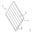
- Figure 13 shows an embodiment of a fibre mat 1 that comprises a first carrier layer 3 and a second carrier layer 12 that are joined for producing a number of ducts 13 in which batches 2 of fibres can be arranged.
- Carrier layers 3, 12 can be joined continuously or in rows of joints, ie eg with a distance between the joints. The joints can be made eg by stitching, gluing or welding.
- the carrier layers 3, 12 are preferably made of a material which is permeable to resin, a non-woven material, braided fibres or woven fibres, including glass fibres.
Landscapes
- Engineering & Computer Science (AREA)
- Textile Engineering (AREA)
- Mechanical Engineering (AREA)
- Chemical & Material Sciences (AREA)
- Inorganic Chemistry (AREA)
- Composite Materials (AREA)
- Nonwoven Fabrics (AREA)
- Reinforced Plastic Materials (AREA)
- Moulding By Coating Moulds (AREA)
- Yarns And Mechanical Finishing Of Yarns Or Ropes (AREA)
Claims (28)
- Verfahren zur Herstellung einer Fasermatte, die zur Verwendung bei der Fertigung einer faserverstärkten Vorrichtung angepasst ist, wobei die Fasermatte zumindest zwei im Wesentlichen in Längsrichtung verlaufende und parallele Bündel aus Fasern umfasst, wobei das Verfahren umfasst, dass die Bündel durch Haltemittel verbunden werden, die jedes Bündel in einem Winkel derart überspannen, dass die Haltemittel einen Einfluss auf jedes Bündel ausüben, welcher Einfluss im Wesentlichen symmetrisch zu einer Achse ist, die in Längsrichtung zwischen den Bündeln liegt.
- Verfahren nach Anspruch 1, wobei die Haltemittel zumindest einen Faden umfassen, der in einem vorbestimmten Muster über zumindest einem der Bündel geführt wird.
- Verfahren nach den Ansprüchen 1 - 2, wobei die Haltemittel zumindest einen Faden umfassen, der in einem vorbestimmten Muster unter zumindest einem der Bündel geführt wird.
- Verfahren nach einem oder mehreren der Ansprüche 2 - 3, wobei der zumindest eine Faden in einem Muster geführt wird, welches Kreuzstiche umfasst.
- Verfahren nach einem oder mehreren der Ansprüche 2 - 4, wobei der zumindest eine Faden in einem Muster geführt wird, welches Stiche umfasst, die in Längsrichtung zwischen den Bündeln anzuordnen sind.
- Verfahren nach einem oder mehreren der Ansprüche 1 - 5, wobei die Fasermatte weiterhin zumindest eine Trägerschicht umfasst; und wobei das Verfahren umfasst, dass die Bündel an der Trägerschicht mit den Haltemitteln gesichert werden.
- Verfahren nach einem oder mehreren der Ansprüche 2 - 6, wobei der Faden in Stichen geführt wird, die eine Länge aufweisen, die dem Ein- bis Zehnfachen der Breite eines benachbarten Bündels entspricht.
- Verfahren nach einem oder mehreren der Ansprüche 2 - 7, wobei Mittel zum Handhaben einer Anzahl von Fäden und Mittel zum Handhaben einer Trägerschicht und einer Anzahl von Fasern vorgesehen sind; und wobei die Mehrheit der Bündel gesichert wird durch die Schritte:a) Vorhandensein einer Anzahl von Nadeln, jede mit einem Nadelöhr, an einem Satz erster Positionen zwischen den Bündeln, geführt durch die Trägerschicht von einer Seite aus, die gegenüber den Bündeln liegt;b) Aufnehmen zumindest zweier Fäden durch jedes Öhr;c) Schließen der Öhre;d) Ziehen der Nadeln durch die Trägerschicht in einer Weise, dass die zumindest zwei Fäden eine Schlaufe bilden;e) Öffnen der Öhre, und Freigeben der Fäden;f) Führen jeder Nadel durch die Schlaufe, die in Schritt d) aus den zumindest zwei Fäden gebildet wurde;g) Führen der Nadeln an einem Satz versetzter Positionen durch die Trägerschicht;h) Fassen zumindest zweier weiterer Fäden durch das Öhr;i) Ziehen der Nadeln durch die Trägerschicht in einer Weise, dass die zumindest zwei Fäden eine Schlaufe bilden;
wobei jeder der zumindest zwei Fäden, vor Schritt b), von gegenüberliegenden Seiten aus über oder unter einem benachbarten Faserbündel geführt wird. - Verfahren nach einem oder mehreren der Ansprüche 2 - 7, wobei Mittel zum Handhaben einer Anzahl von Fäden und Mittel zum Handhaben einer Trägerschicht und einer Anzahl von Faserbündeln vorgesehen sind, und wobei die Mehrheit der Bündel gesichert wird in den Schritten:j) Vorhandensein einer Anzahl von Nadeln, jeweils mit einem Nadelöhr, an einem Satz erster Positionen zwischen den Bündeln, geführt durch die Trägerschicht von einer Seite aus, die gegenüber den Bündeln liegt;k) Aufnehmen zumindest zweier Fäden durch jedes Öhr;l) Schließen der Öhre;m) Ziehen der Nadeln durch die Trägerschicht in einer Weise, dass die zumindest zwei Fäden eine Schlaufe bilden;n) Öffnen der Öhre, und Freigeben der Fäden;o) Führen jeder Nadel durch die Schlaufe, die in Schritt m) aus den zumindest zwei Fäden gebildet wurde;p) Führen der Nadeln an einem Satz versetzter Positionen auf der Trägerschicht durch die Trägerschicht;q) Aufnehmen zumindest eines Fadens durch das Öhr;r) Ziehen der Nadeln durch die Trägerschicht in einer Weise, dass der zumindest eine Faden eine Schlaufe bildet;wobei jeder der zumindest zwei Fäden, vor Schritt k), in einem vorbestimmten Muster geführt wird, einschließlich bevorzugt von gegenüberliegenden Seiten aus jeweils über oder unter einem benachbarten Faserbündel und in Längsrichtung zwischen einem ersten und einem zweiten benachbarten Bündel.
- Verfahren nach Anspruch 6, wobei die Haltemittel eine zweite Trägerschicht umfassen, die an der ersten Trägerschicht durch zumindest drei Nahtstellen oder Reihen von Nahtstellen, die parallel verlaufen, gesichert wird, wodurch die erste und zweite Trägerschicht mit den Nahtstellen eine Anzahl röhrenförmiger Teile bilden, in denen die Bündel angeordnet werden.
- Verfahren nach Anspruch 10, wobei die Nahtstellen oder Reihen von Nahtstellen mittels eines Vorgangs gebildet werden, der aus einer Gruppe ausgewählt wird, welche Nähen, Kleben und Schweißen umfasst.
- Verfahren nach einem oder mehreren der Ansprüche 6 - 11, wobei die erste Trägerschicht aus einer Gruppe ausgewählt wird, umfassend ein Material, das harzdurchlässig ist, einschließlich in der Form von Fasern, die diagonal oder quer in Bezug auf Faserbündel angeordnet sind, ein Vliesmaterial, geflochtene Fasern und gewobene Fasern, einschließlich Glasfasern.
- Verfahren nach einem oder mehreren der Ansprüche 1 - 9, wobei die Fäden mit einer Zugkraft geführt werden, die so angepasst ist, dass den Bündeln in Querrichtung eine gerundete Kontur verliehen wird.
- Verfahren nach Anspruch 10 oder 11, wobei die Fasermenge in den Bündeln bezüglich der Größe der röhrenförmigen Teile angepasst wird mit der Wirkung, dass den Bündeln in Querrichtung eine gerundete Kontur verliehen wird.
- Verfahren nach einem oder mehreren der Ansprüche 1 - 14, wobei die Bündel Fasern umfassen, die aus einer Gruppe ausgewählt werden, welche Glasfasern, Carbonfasern, Fasern, die einen geringeren elektrischen Widerstand als Glasfasern besitzen, und Kombinationen aus Fasern verschiedener Materialien umfasst.
- Fasermatte, die zur Verwendung bei der Fertigung einer faserverstärkten Vorrichtung angepasst ist, welche Fasermatte zumindest zwei im Wesentlichen in Längsrichtung verlaufende und parallele Bündel aus Fasern umfasst, wobei die Bündel durch Haltemittel verbunden sind, die jedes Bündel in einem Winkel überspannen, wodurch ein Einfluss auf jedes Bündel ausgeübt wird, wobei der Einfluss im Wesentlichen symmetrisch zu einer Achse ist, die in Längsrichtung zwischen den Bündeln liegt.
- Fasermatte nach Anspruch 16, wobei die Haltemittel zumindest einen Faden umfassen, der in einem vorbestimmten Muster über zumindest einem der Bündel geführt wird.
- Fasermatte nach den Ansprüchen 16 - 17, wobei die Haltemittel zumindest einen Faden umfassen, der in einem vorbestimmten Muster unter zumindest einem der Bündel geführt wird.
- Fasermatte nach einem oder mehreren der Ansprüche 17 - 18, wobei der zumindest eine Faden in einem Muster geführt wird, welches Kreuzstiche umfasst.
- Fasermatte nach einem oder mehreren der Ansprüche 17 - 19, wobei der zumindest eine Faden in einem Muster geführt wird, welches Stiche umfasst, die in Längsrichtung zwischen den Bündeln angeordnet sind.
- Fasermatte nach einem oder mehreren der Ansprüche 16 - 20, wobei die Fasermatte weiterhin zumindest eine erste Trägerschicht umfasst; und umfasst, dass die Bündel an der Trägerschicht durch die Haltemittel gesichert sind.
- Fasermatte nach einem oder mehreren der Ansprüche 17 - 21, wobei der Faden in Stichen geführt wird, die eine Länge aufweisen, die dem Ein- bis Zehnfachen der Breite eines benachbarten Bündels entspricht.
- Fasermatte nach Anspruch 16, wobei die Haltemittel eine zweite Trägerschicht umfassen, die an der ersten Trägerschicht durch zumindest drei Nahtstellen oder Reihen von Nahtstellen, die parallel verlaufen, gesichert ist, wodurch die erste und die zweite Trägerschicht mit den Nahtstellen eine Anzahl röhrenförmiger Teile bilden, in denen die Bündel angeordnet sind.
- Fasermatte nach Anspruch 23, wobei die Nahtstellen oder Reihen von Nahtstellen in einem Vorgang gebildet sind, der aus einer Gruppe ausgewählt ist, welche Nähen, Kleben und Schweißen umfasst.
- Fasermatte nach einem oder mehreren der Ansprüche 16 - 24, wobei die erste Trägerschicht aus einer Gruppe ausgewählt ist, umfassend ein Material, das harzdurchlässig ist, einschließlich in der Form von Fasern, die diagonal oder quer in Bezug auf Faserbündel angeordnet sind, ein Vliesmaterial, geflochtene Fasern und gewobene Fasern, einschließlich Glasfasern.
- Fasermatte nach einem oder mehreren der Ansprüche 16 - 25, wobei die Bündel Fasern umfassen, die aus einer Gruppe ausgewählt sind, welche Glasfasern, Carbonfasern, Fasern, die einen geringeren elektrischen Widerstand als Glasfasern besitzen, und Kombinationen aus Fasern verschiedener Materialien umfasst.
- Verwendung einer Fasermatte nach einem oder mehreren der Ansprüche 16 - 26, wobei die Verwendung das VARTM (Vacuum Assisted Resin Transfer Moulding) einer faserverstärkten Vorrichtung umfasst.
- Verwendung nach Anspruch 27, wobei eine Vorrichtung gemouldet wird, die als Bestandteil in/von einem Blatt für eine Windenergieanlage gestaltet ist.
Applications Claiming Priority (3)
| Application Number | Priority Date | Filing Date | Title |
|---|---|---|---|
| DKPA200400095 | 2004-01-26 | ||
| DK200401440A DK176051B1 (da) | 2004-01-26 | 2004-09-22 | Fibermåtte og en metode til fremstilling af en fibermåtte |
| PCT/DK2005/000019 WO2005071152A1 (en) | 2004-01-26 | 2005-01-14 | A fibre mat and a method of manufacturing a fibre mat |
Publications (2)
| Publication Number | Publication Date |
|---|---|
| EP1709228A1 EP1709228A1 (de) | 2006-10-11 |
| EP1709228B1 true EP1709228B1 (de) | 2009-03-25 |
Family
ID=34809653
Family Applications (1)
| Application Number | Title | Priority Date | Filing Date |
|---|---|---|---|
| EP05700569A Expired - Lifetime EP1709228B1 (de) | 2004-01-26 | 2005-01-14 | Fasermatte und verfahren zur herstellung einer fasermatte |
Country Status (13)
| Country | Link |
|---|---|
| US (1) | US7726253B2 (de) |
| EP (1) | EP1709228B1 (de) |
| CN (1) | CN1914366B (de) |
| AT (1) | ATE426699T1 (de) |
| AU (1) | AU2005206250B2 (de) |
| BR (1) | BRPI0507015B1 (de) |
| CA (1) | CA2552042C (de) |
| DE (1) | DE602005013488D1 (de) |
| DK (1) | DK176051B1 (de) |
| ES (1) | ES2324942T3 (de) |
| NO (1) | NO338016B1 (de) |
| RU (1) | RU2352697C2 (de) |
| WO (1) | WO2005071152A1 (de) |
Families Citing this family (20)
| Publication number | Priority date | Publication date | Assignee | Title |
|---|---|---|---|---|
| FR2890398B1 (fr) * | 2005-09-07 | 2007-11-30 | Saint Gobain Vetrotex | Etoffe complexe pour moulage par infusion |
| FR2892716B1 (fr) | 2005-10-28 | 2008-04-18 | Saint Gobain Vetrotex | Composition de verre resistant aux alcalis et aux acides pour la fabrication de fils de verre |
| DE102006006337A1 (de) | 2006-02-11 | 2007-08-16 | Kümpers GmbH & Co. KG | Räumliche textile Bauteilstruktur auf hochfesten Fäden, sowie Verfahren zu deren Herstellung |
| FI20065659L (fi) * | 2006-10-16 | 2008-04-17 | Paroc Oy Ab | Mineraalivillaa olevan lamellimaton valmistusmenetelmiä ja lamellimatto |
| FR2907777B1 (fr) | 2006-10-25 | 2009-01-30 | Saint Gobain Vetrotex | Composition de verre resistant aux milieux chimiques pour la fabrication de fils de verre de renforcement. |
| ES2372440T3 (es) * | 2007-11-09 | 2012-01-19 | Vestas Wind Systems A/S | Procedimiento para fabricar una pala de aerogenerador y uso de una esterilla estructural para reforzar una estructura de pala de aerogenerador. |
| FR2949239B1 (fr) * | 2009-08-21 | 2011-10-28 | Gilbert Chomarat | Renfort a meche de fils de verre parralleles. |
| US10137542B2 (en) | 2010-01-14 | 2018-11-27 | Senvion Gmbh | Wind turbine rotor blade components and machine for making same |
| MX341495B (es) | 2010-01-14 | 2016-08-23 | Neptco Inc * | Componentes de pala de rotor de turbina eolica y metodos para la fabricacion de los mismos. |
| WO2012096696A1 (en) | 2011-01-12 | 2012-07-19 | Stanford University | Composite laminated structures and methods for manufacturing and using the same |
| PT2874803T (pt) * | 2012-07-20 | 2017-01-17 | Ahlstroem Oy | Um reforço costurado unidirecional ou multiaxial e um método para produzir o mesmo |
| DK3092331T3 (da) * | 2014-01-10 | 2020-02-03 | Ocv Intellectual Capital Llc | Ikke-vævet ensrettet fiberforstærket stof |
| CN111328354B (zh) * | 2017-11-10 | 2022-12-06 | 株式会社可乐丽 | 纤维构造体及其制造方法 |
| FR3084676B1 (fr) * | 2018-07-31 | 2020-10-02 | Nobrak | Procede de fabrication d'une nappe de fils par points de couture, notamment pour la realisation de pieces en materiaux composites |
| WO2020041107A1 (en) | 2018-08-21 | 2020-02-27 | Ocv Intellectual Capital, Llc | Multiaxial reinforcing fabric with a stitching yarn for improved fabric infusion |
| EP3841237A1 (de) | 2018-08-21 | 2021-06-30 | Owens-Corning Intellectual Capital, LLC | Hybrides verstärkungsgewebe |
| JP7096106B2 (ja) * | 2018-08-28 | 2022-07-05 | 株式会社Subaru | プリフォーム賦形方法及び複合材成形方法 |
| JP7193282B2 (ja) | 2018-09-14 | 2022-12-20 | 株式会社Subaru | プリフォーム賦形方法及び複合材成形方法 |
| CN109281058B (zh) * | 2018-10-19 | 2020-10-27 | 中原工学院 | 一种多层级纤维网及其制备方法 |
| US20230257634A1 (en) * | 2020-07-17 | 2023-08-17 | Technitex Sachsen GmbH | Textile Carrier Material for Adhesive Tapes Having a Formed Tear-Off Edge |
Family Cites Families (15)
| Publication number | Priority date | Publication date | Assignee | Title |
|---|---|---|---|---|
| US1204046A (en) * | 1914-08-22 | 1916-11-07 | John Edward Mcloughlin | Seam. |
| US2518407A (en) * | 1949-01-24 | 1950-08-08 | Weinberg Robert | Elastic tape |
| US3274805A (en) * | 1963-08-09 | 1966-09-27 | Indian Head Mills Inc | Fabric and method |
| US3405598A (en) * | 1966-02-02 | 1968-10-15 | Iwai Yasuaki | Cord for piled rug |
| US3481245A (en) * | 1967-07-31 | 1969-12-02 | Takashi Kamitani | Tube mat used as a carpet |
| US3567565A (en) * | 1967-11-09 | 1971-03-02 | Burlington Industries Inc | Laminate of foam and stitch bonded fabric |
| NL7008333A (de) * | 1969-06-30 | 1971-12-13 | ||
| US4183993A (en) * | 1978-01-30 | 1980-01-15 | Gulf States Paper Corporation | Reinforced fabric and laminate made therewith |
| US4854135A (en) * | 1985-10-04 | 1989-08-08 | Burlington Industries, Inc. | Antique satin weft inserted warp knit drapery fabric |
| US4671988A (en) * | 1986-08-19 | 1987-06-09 | Dowell James R | Camouflage knitted article |
| FR2605929B1 (fr) * | 1986-11-05 | 1989-03-31 | Brochier Sa | Materiau textile permettant la realisation d'articles stratifies renforces par moulage par injection |
| DE68919825T2 (de) * | 1988-09-02 | 1995-07-06 | Gunze Kk | Thermisches Formgebungsverfahren und Gestrick zur Verwendung in dieser Methode. |
| CA2025126C (en) * | 1989-09-13 | 2000-05-02 | Dimitri Peter Zafiroglu | Stitch-stabilized nonwoven fabric |
| DE4419985C2 (de) * | 1994-06-08 | 1996-04-04 | Univ Dresden Tech | Mehrlagengestrick und Verfahren zu seiner Herstellung |
| RU2185469C2 (ru) * | 1996-10-18 | 2002-07-20 | Е.И. Дюпон Де Немур Энд Компани | Способ быстрого изготовления материала |
-
2004
- 2004-09-22 DK DK200401440A patent/DK176051B1/da not_active IP Right Cessation
-
2005
- 2005-01-14 AU AU2005206250A patent/AU2005206250B2/en not_active Expired
- 2005-01-14 CN CN2005800032656A patent/CN1914366B/zh not_active Expired - Lifetime
- 2005-01-14 BR BRPI0507015-5B1A patent/BRPI0507015B1/pt not_active IP Right Cessation
- 2005-01-14 DE DE602005013488T patent/DE602005013488D1/de not_active Expired - Lifetime
- 2005-01-14 AT AT05700569T patent/ATE426699T1/de not_active IP Right Cessation
- 2005-01-14 RU RU2006130749/12A patent/RU2352697C2/ru active
- 2005-01-14 CA CA2552042A patent/CA2552042C/en not_active Expired - Lifetime
- 2005-01-14 ES ES05700569T patent/ES2324942T3/es not_active Expired - Lifetime
- 2005-01-14 WO PCT/DK2005/000019 patent/WO2005071152A1/en not_active Ceased
- 2005-01-14 US US10/586,820 patent/US7726253B2/en active Active
- 2005-01-14 EP EP05700569A patent/EP1709228B1/de not_active Expired - Lifetime
-
2006
- 2006-08-25 NO NO20063800A patent/NO338016B1/no unknown
Also Published As
| Publication number | Publication date |
|---|---|
| CA2552042A1 (en) | 2005-08-04 |
| US20070193491A1 (en) | 2007-08-23 |
| DK176051B1 (da) | 2006-02-27 |
| US7726253B2 (en) | 2010-06-01 |
| CN1914366A (zh) | 2007-02-14 |
| BRPI0507015B1 (pt) | 2015-02-03 |
| AU2005206250A1 (en) | 2005-08-04 |
| BRPI0507015A (pt) | 2007-06-05 |
| CA2552042C (en) | 2012-10-23 |
| CN1914366B (zh) | 2012-11-28 |
| NO20063800L (no) | 2006-08-25 |
| DE602005013488D1 (de) | 2009-05-07 |
| RU2352697C2 (ru) | 2009-04-20 |
| EP1709228A1 (de) | 2006-10-11 |
| WO2005071152A1 (en) | 2005-08-04 |
| AU2005206250B2 (en) | 2010-06-17 |
| RU2006130749A (ru) | 2008-03-10 |
| ES2324942T3 (es) | 2009-08-20 |
| NO338016B1 (no) | 2016-07-18 |
| ATE426699T1 (de) | 2009-04-15 |
Similar Documents
| Publication | Publication Date | Title |
|---|---|---|
| EP1709228B1 (de) | Fasermatte und verfahren zur herstellung einer fasermatte | |
| CN103895857B (zh) | 加强桁条及其制造方法 | |
| JP4526698B2 (ja) | 複合材成形品及びその製造方法 | |
| RU2549955C2 (ru) | Многоосная укладка, скрепленная точечной сваркой, полученной с помощью вставных термопластичных тонких нетканых материалов | |
| EP3012094B1 (de) | Hockeykelle mit umwickeltem, genähtem kern | |
| CN104755664B (zh) | 纺织件、带有纺织件的复合材料元件及其制造方法 | |
| JP2009537691A (ja) | 成形材料 | |
| EP2687356A1 (de) | Eindirektionale Verstärkung und Verfahren zur Herstellung einer eindirektionalen Verstärkung | |
| JPH01289837A (ja) | 切れ目を入れた連続繊維プリプレグを使用する繊維強化熱可塑性プラスチックの製造法 | |
| JPH0422933B2 (de) | ||
| CA2764137A1 (en) | Stiffening sheet for use in a fibre reinforced laminate, fibre reinforced laminate and wind turbine blade, and a method of manufacturing a fibre reinforced laminate | |
| KR20110091706A (ko) | 비선형 레그들을 갖는 pi-형상 모재 및 그 제조방법 | |
| KR20100112134A (ko) | 일체로 직조된 3차원 프리폼과 이의 제조방법 | |
| EP0391970A1 (de) | Multidirektionales, starkes, leichtes, verflochtenes material und verfahren zu seiner herstellung | |
| US11691359B2 (en) | Multiple layer article with interactive reinforcements linear ribbon fiber reinforcement for composite forms | |
| CA2085253A1 (en) | Manufacture of a composite material | |
| JP2020505258A (ja) | 複合材料のための転写システム | |
| JPH085080B2 (ja) | 繊維強化熱可塑性プラスチツクの製造法 | |
| EP1946912B1 (de) | Verfahren zur Herstellung eines Artikels aus Verbundmaterial, dadurch hergestellter Artikel und Randstreifen | |
| BRPI0414826B1 (pt) | pano de reforço infusível desprovido de pregas e processo para produção de um pano | |
| JP2003513174A (ja) | シート状の織物材料 | |
| JP4133250B2 (ja) | 多軸強化繊維シート及びその製造方法 | |
| CN109923254B (zh) | 复合材料用增强基材、复合材料以及复合材料用增强基材的制造方法 | |
| MXPA06008004A (en) | A fibre mat and a method of manufacturing a fibre mat | |
| JP6862994B2 (ja) | 複合強化繊維シート |
Legal Events
| Date | Code | Title | Description |
|---|---|---|---|
| PUAI | Public reference made under article 153(3) epc to a published international application that has entered the european phase |
Free format text: ORIGINAL CODE: 0009012 |
|
| 17P | Request for examination filed |
Effective date: 20060705 |
|
| AK | Designated contracting states |
Kind code of ref document: A1 Designated state(s): AT BE BG CH CY CZ DE DK EE ES FI FR GB GR HU IE IS IT LI LT LU MC NL PL PT RO SE SI SK TR |
|
| AX | Request for extension of the european patent |
Extension state: LV |
|
| RAX | Requested extension states of the european patent have changed |
Extension state: LV Payment date: 20060705 |
|
| GRAP | Despatch of communication of intention to grant a patent |
Free format text: ORIGINAL CODE: EPIDOSNIGR1 |
|
| GRAP | Despatch of communication of intention to grant a patent |
Free format text: ORIGINAL CODE: EPIDOSNIGR1 |
|
| GRAS | Grant fee paid |
Free format text: ORIGINAL CODE: EPIDOSNIGR3 |
|
| GRAA | (expected) grant |
Free format text: ORIGINAL CODE: 0009210 |
|
| AK | Designated contracting states |
Kind code of ref document: B1 Designated state(s): AT BE BG CH CY CZ DE DK EE ES FI FR GB GR HU IE IS IT LI LT LU MC NL PL PT RO SE SI SK TR |
|
| AX | Request for extension of the european patent |
Extension state: LV |
|
| REG | Reference to a national code |
Ref country code: GB Ref legal event code: FG4D |
|
| REG | Reference to a national code |
Ref country code: CH Ref legal event code: EP |
|
| REG | Reference to a national code |
Ref country code: IE Ref legal event code: FG4D |
|
| REF | Corresponds to: |
Ref document number: 602005013488 Country of ref document: DE Date of ref document: 20090507 Kind code of ref document: P |
|
| PG25 | Lapsed in a contracting state [announced via postgrant information from national office to epo] |
Ref country code: SI Free format text: LAPSE BECAUSE OF FAILURE TO SUBMIT A TRANSLATION OF THE DESCRIPTION OR TO PAY THE FEE WITHIN THE PRESCRIBED TIME-LIMIT Effective date: 20090325 Ref country code: FI Free format text: LAPSE BECAUSE OF FAILURE TO SUBMIT A TRANSLATION OF THE DESCRIPTION OR TO PAY THE FEE WITHIN THE PRESCRIBED TIME-LIMIT Effective date: 20090325 Ref country code: LT Free format text: LAPSE BECAUSE OF FAILURE TO SUBMIT A TRANSLATION OF THE DESCRIPTION OR TO PAY THE FEE WITHIN THE PRESCRIBED TIME-LIMIT Effective date: 20090325 |
|
| REG | Reference to a national code |
Ref country code: ES Ref legal event code: FG2A Ref document number: 2324942 Country of ref document: ES Kind code of ref document: T3 |
|
| PG25 | Lapsed in a contracting state [announced via postgrant information from national office to epo] |
Ref country code: AT Free format text: LAPSE BECAUSE OF FAILURE TO SUBMIT A TRANSLATION OF THE DESCRIPTION OR TO PAY THE FEE WITHIN THE PRESCRIBED TIME-LIMIT Effective date: 20090325 Ref country code: PL Free format text: LAPSE BECAUSE OF FAILURE TO SUBMIT A TRANSLATION OF THE DESCRIPTION OR TO PAY THE FEE WITHIN THE PRESCRIBED TIME-LIMIT Effective date: 20090325 Ref country code: SE Free format text: LAPSE BECAUSE OF FAILURE TO SUBMIT A TRANSLATION OF THE DESCRIPTION OR TO PAY THE FEE WITHIN THE PRESCRIBED TIME-LIMIT Effective date: 20090625 |
|
| NLV1 | Nl: lapsed or annulled due to failure to fulfill the requirements of art. 29p and 29m of the patents act | ||
| PG25 | Lapsed in a contracting state [announced via postgrant information from national office to epo] |
Ref country code: BE Free format text: LAPSE BECAUSE OF FAILURE TO SUBMIT A TRANSLATION OF THE DESCRIPTION OR TO PAY THE FEE WITHIN THE PRESCRIBED TIME-LIMIT Effective date: 20090325 |
|
| PG25 | Lapsed in a contracting state [announced via postgrant information from national office to epo] |
Ref country code: CZ Free format text: LAPSE BECAUSE OF FAILURE TO SUBMIT A TRANSLATION OF THE DESCRIPTION OR TO PAY THE FEE WITHIN THE PRESCRIBED TIME-LIMIT Effective date: 20090325 Ref country code: EE Free format text: LAPSE BECAUSE OF FAILURE TO SUBMIT A TRANSLATION OF THE DESCRIPTION OR TO PAY THE FEE WITHIN THE PRESCRIBED TIME-LIMIT Effective date: 20090325 |
|
| PG25 | Lapsed in a contracting state [announced via postgrant information from national office to epo] |
Ref country code: IS Free format text: LAPSE BECAUSE OF FAILURE TO SUBMIT A TRANSLATION OF THE DESCRIPTION OR TO PAY THE FEE WITHIN THE PRESCRIBED TIME-LIMIT Effective date: 20090725 Ref country code: RO Free format text: LAPSE BECAUSE OF FAILURE TO SUBMIT A TRANSLATION OF THE DESCRIPTION OR TO PAY THE FEE WITHIN THE PRESCRIBED TIME-LIMIT Effective date: 20090325 Ref country code: SK Free format text: LAPSE BECAUSE OF FAILURE TO SUBMIT A TRANSLATION OF THE DESCRIPTION OR TO PAY THE FEE WITHIN THE PRESCRIBED TIME-LIMIT Effective date: 20090325 Ref country code: NL Free format text: LAPSE BECAUSE OF FAILURE TO SUBMIT A TRANSLATION OF THE DESCRIPTION OR TO PAY THE FEE WITHIN THE PRESCRIBED TIME-LIMIT Effective date: 20090325 |
|
| PG25 | Lapsed in a contracting state [announced via postgrant information from national office to epo] |
Ref country code: BG Free format text: LAPSE BECAUSE OF FAILURE TO SUBMIT A TRANSLATION OF THE DESCRIPTION OR TO PAY THE FEE WITHIN THE PRESCRIBED TIME-LIMIT Effective date: 20090625 Ref country code: DK Free format text: LAPSE BECAUSE OF FAILURE TO SUBMIT A TRANSLATION OF THE DESCRIPTION OR TO PAY THE FEE WITHIN THE PRESCRIBED TIME-LIMIT Effective date: 20090325 |
|
| PLBE | No opposition filed within time limit |
Free format text: ORIGINAL CODE: 0009261 |
|
| STAA | Information on the status of an ep patent application or granted ep patent |
Free format text: STATUS: NO OPPOSITION FILED WITHIN TIME LIMIT |
|
| 26N | No opposition filed |
Effective date: 20091229 |
|
| PG25 | Lapsed in a contracting state [announced via postgrant information from national office to epo] |
Ref country code: MC Free format text: LAPSE BECAUSE OF NON-PAYMENT OF DUE FEES Effective date: 20100131 |
|
| REG | Reference to a national code |
Ref country code: CH Ref legal event code: PL |
|
| REG | Reference to a national code |
Ref country code: IE Ref legal event code: MM4A |
|
| PG25 | Lapsed in a contracting state [announced via postgrant information from national office to epo] |
Ref country code: LI Free format text: LAPSE BECAUSE OF NON-PAYMENT OF DUE FEES Effective date: 20100131 Ref country code: GR Free format text: LAPSE BECAUSE OF FAILURE TO SUBMIT A TRANSLATION OF THE DESCRIPTION OR TO PAY THE FEE WITHIN THE PRESCRIBED TIME-LIMIT Effective date: 20090626 Ref country code: CH Free format text: LAPSE BECAUSE OF NON-PAYMENT OF DUE FEES Effective date: 20100131 |
|
| PG25 | Lapsed in a contracting state [announced via postgrant information from national office to epo] |
Ref country code: IE Free format text: LAPSE BECAUSE OF NON-PAYMENT OF DUE FEES Effective date: 20100114 |
|
| PG25 | Lapsed in a contracting state [announced via postgrant information from national office to epo] |
Ref country code: CY Free format text: LAPSE BECAUSE OF FAILURE TO SUBMIT A TRANSLATION OF THE DESCRIPTION OR TO PAY THE FEE WITHIN THE PRESCRIBED TIME-LIMIT Effective date: 20090325 |
|
| PG25 | Lapsed in a contracting state [announced via postgrant information from national office to epo] |
Ref country code: LU Free format text: LAPSE BECAUSE OF NON-PAYMENT OF DUE FEES Effective date: 20100114 Ref country code: PT Free format text: LAPSE BECAUSE OF FAILURE TO SUBMIT A TRANSLATION OF THE DESCRIPTION OR TO PAY THE FEE WITHIN THE PRESCRIBED TIME-LIMIT Effective date: 20090825 Ref country code: HU Free format text: LAPSE BECAUSE OF FAILURE TO SUBMIT A TRANSLATION OF THE DESCRIPTION OR TO PAY THE FEE WITHIN THE PRESCRIBED TIME-LIMIT Effective date: 20090926 |
|
| PG25 | Lapsed in a contracting state [announced via postgrant information from national office to epo] |
Ref country code: TR Free format text: LAPSE BECAUSE OF FAILURE TO SUBMIT A TRANSLATION OF THE DESCRIPTION OR TO PAY THE FEE WITHIN THE PRESCRIBED TIME-LIMIT Effective date: 20090325 |
|
| REG | Reference to a national code |
Ref country code: FR Ref legal event code: PLFP Year of fee payment: 12 |
|
| REG | Reference to a national code |
Ref country code: FR Ref legal event code: PLFP Year of fee payment: 13 |
|
| REG | Reference to a national code |
Ref country code: FR Ref legal event code: PLFP Year of fee payment: 14 |
|
| P01 | Opt-out of the competence of the unified patent court (upc) registered |
Effective date: 20230522 |
|
| PGFP | Annual fee paid to national office [announced via postgrant information from national office to epo] |
Ref country code: GB Payment date: 20231219 Year of fee payment: 20 |
|
| PGFP | Annual fee paid to national office [announced via postgrant information from national office to epo] |
Ref country code: FR Payment date: 20231219 Year of fee payment: 20 |
|
| PGFP | Annual fee paid to national office [announced via postgrant information from national office to epo] |
Ref country code: ES Payment date: 20240202 Year of fee payment: 20 |
|
| PGFP | Annual fee paid to national office [announced via postgrant information from national office to epo] |
Ref country code: DE Payment date: 20231219 Year of fee payment: 20 |
|
| PGFP | Annual fee paid to national office [announced via postgrant information from national office to epo] |
Ref country code: IT Payment date: 20240102 Year of fee payment: 20 |
|
| REG | Reference to a national code |
Ref country code: DE Ref legal event code: R071 Ref document number: 602005013488 Country of ref document: DE |
|
| REG | Reference to a national code |
Ref country code: ES Ref legal event code: FD2A Effective date: 20250124 |
|
| REG | Reference to a national code |
Ref country code: GB Ref legal event code: PE20 Expiry date: 20250113 |
|
| PG25 | Lapsed in a contracting state [announced via postgrant information from national office to epo] |
Ref country code: ES Free format text: LAPSE BECAUSE OF EXPIRATION OF PROTECTION Effective date: 20250115 |
|
| PG25 | Lapsed in a contracting state [announced via postgrant information from national office to epo] |
Ref country code: GB Free format text: LAPSE BECAUSE OF EXPIRATION OF PROTECTION Effective date: 20250113 |