EP1709319B1 - Injecteur de carburant a commande de pointeau directe - Google Patents
Injecteur de carburant a commande de pointeau directe Download PDFInfo
- Publication number
- EP1709319B1 EP1709319B1 EP04802766A EP04802766A EP1709319B1 EP 1709319 B1 EP1709319 B1 EP 1709319B1 EP 04802766 A EP04802766 A EP 04802766A EP 04802766 A EP04802766 A EP 04802766A EP 1709319 B1 EP1709319 B1 EP 1709319B1
- Authority
- EP
- European Patent Office
- Prior art keywords
- booster
- valve member
- injection valve
- pressure
- region
- Prior art date
- Legal status (The legal status is an assumption and is not a legal conclusion. Google has not performed a legal analysis and makes no representation as to the accuracy of the status listed.)
- Expired - Lifetime
Links
- 239000000446 fuel Substances 0.000 title claims description 58
- 238000002347 injection Methods 0.000 claims description 103
- 239000007924 injection Substances 0.000 claims description 103
- 238000002485 combustion reaction Methods 0.000 claims description 12
- 230000007704 transition Effects 0.000 claims description 7
- 238000007789 sealing Methods 0.000 description 9
- 230000007423 decrease Effects 0.000 description 4
- 239000013078 crystal Substances 0.000 description 3
- 238000003860 storage Methods 0.000 description 3
- 230000015572 biosynthetic process Effects 0.000 description 1
- 238000010276 construction Methods 0.000 description 1
- 239000002828 fuel tank Substances 0.000 description 1
- 238000004519 manufacturing process Methods 0.000 description 1
- 238000000034 method Methods 0.000 description 1
- 238000011144 upstream manufacturing Methods 0.000 description 1
- 238000003466 welding Methods 0.000 description 1
Images
Classifications
-
- F—MECHANICAL ENGINEERING; LIGHTING; HEATING; WEAPONS; BLASTING
- F02—COMBUSTION ENGINES; HOT-GAS OR COMBUSTION-PRODUCT ENGINE PLANTS
- F02M—SUPPLYING COMBUSTION ENGINES IN GENERAL WITH COMBUSTIBLE MIXTURES OR CONSTITUENTS THEREOF
- F02M51/00—Fuel-injection apparatus characterised by being operated electrically
- F02M51/06—Injectors peculiar thereto with means directly operating the valve needle
- F02M51/0603—Injectors peculiar thereto with means directly operating the valve needle using piezoelectric or magnetostrictive operating means
-
- F—MECHANICAL ENGINEERING; LIGHTING; HEATING; WEAPONS; BLASTING
- F02—COMBUSTION ENGINES; HOT-GAS OR COMBUSTION-PRODUCT ENGINE PLANTS
- F02M—SUPPLYING COMBUSTION ENGINES IN GENERAL WITH COMBUSTIBLE MIXTURES OR CONSTITUENTS THEREOF
- F02M2200/00—Details of fuel-injection apparatus, not otherwise provided for
- F02M2200/21—Fuel-injection apparatus with piezoelectric or magnetostrictive elements
-
- F—MECHANICAL ENGINEERING; LIGHTING; HEATING; WEAPONS; BLASTING
- F02—COMBUSTION ENGINES; HOT-GAS OR COMBUSTION-PRODUCT ENGINE PLANTS
- F02M—SUPPLYING COMBUSTION ENGINES IN GENERAL WITH COMBUSTIBLE MIXTURES OR CONSTITUENTS THEREOF
- F02M2200/00—Details of fuel-injection apparatus, not otherwise provided for
- F02M2200/70—Linkage between actuator and actuated element, e.g. between piezoelectric actuator and needle valve or pump plunger
- F02M2200/703—Linkage between actuator and actuated element, e.g. between piezoelectric actuator and needle valve or pump plunger hydraulic
-
- F—MECHANICAL ENGINEERING; LIGHTING; HEATING; WEAPONS; BLASTING
- F02—COMBUSTION ENGINES; HOT-GAS OR COMBUSTION-PRODUCT ENGINE PLANTS
- F02M—SUPPLYING COMBUSTION ENGINES IN GENERAL WITH COMBUSTIBLE MIXTURES OR CONSTITUENTS THEREOF
- F02M61/00—Fuel-injectors not provided for in groups F02M39/00 - F02M57/00 or F02M67/00
- F02M61/04—Fuel-injectors not provided for in groups F02M39/00 - F02M57/00 or F02M67/00 having valves, e.g. having a plurality of valves in series
- F02M61/10—Other injectors with elongated valve bodies, i.e. of needle-valve type
- F02M61/12—Other injectors with elongated valve bodies, i.e. of needle-valve type characterised by the provision of guiding or centring means for valve bodies
Definitions
- the injection pressure is provided via a high-pressure accumulator. Due to the large amount of fuel in the high-pressure accumulator compared to the injection quantity, pressure fluctuations during the injection process are avoided.
- the operation of the fuel injectors is carried out hydraulically with the fuel provided via the high-pressure accumulator.
- Fuel injectors as used in the prior art for high-pressure storage systems, z. B. from Mollenhauer, Manual Diesel Engines, Second Edition, Springer-Verlag, Berlin, 2002 known.
- both the opening and the closing operation is hydraulically controlled.
- a control chamber in which fuel is under injection pressure closed by a control valve.
- the fuel pressure acts on the rear side of a control piston, which acts into the control chamber, and on a pressure shoulder on an injection valve closing the injection openings.
- the hydraulic force on the back of the control piston of the hydraulic force acting on the pressure shoulder opposite. Due to the larger area on the control piston, the nozzle remains closed.
- the control valve opens the control chamber, the pressure in the control chamber is reduced and the hydraulic force on the pressure shoulder is greater than the pressure force acting on the back of the control piston. This causes the injection valve member to open.
- a fuel injector in which a pressure booster connected to a piezo actuator acts on an injection valve member via a booster chamber.
- the booster chamber is delimited by a pot-shaped sleeve, the fuel passing via the sleeve via a bypass to a pressure chamber located upstream of the injection openings.
- the cup-shaped sleeve of the pressure booster and the injection valve member is received in guides, so that the booster chamber is hydraulically sealed by the guides.
- the fuel injector designed according to the invention provides a fuel injector for high-pressure storage systems with a compact construction.
- an actuator of the fuel injector acts directly on a pressure booster designed as a booster piston.
- the actuator is z.
- As a piezoelectric actuator an electromagnet or a hydraulic / mechanical actuator.
- the actuator acts directly on an upper end face of the booster piston.
- a lower end face of the pressure booster forms one side of a booster chamber, and an end face of a stepped injection valve member bounds the booster chamber on the opposite side.
- a shoulder is formed in the interpreter room, so that the interpreter room tapers from a large to a smaller diameter.
- the larger diameter of the booster chamber faces the pressure translator of the same diameter, while the region of the small diameter booster chamber faces the injection valve member.
- the injection valve member is stepped in a translator area, a guide area and an original area. To open injection openings, the injection valve member moves in the direction of the pressure booster. In this case, the end face of the compiler area of the injection valve member moves into the interrupter space.
- the compiler area of the injection valve member is surrounded by a spring space in which a spring element is accommodated.
- the spring element is preferably designed as a spiral spring.
- the spring element On one side, the spring element is supported on a ring, which rests on an extension formed between the compiler area and the guide area of the injection valve member.
- the spring element On the other hand, the spring element is supported against an end face of a ring surrounding the compiler portion of the injection valve member sleeve.
- the sleeve is provided with a biting edge.
- the fuel used for the operation of the internal combustion engine flows from a high-pressure accumulator into an annular space surrounding the actuator. About absorbed in the injector bypasses the fuel flows from the annulus in the spring chamber. About guide leakage between the compiler area of the injection valve member and the sleeve fuel enters the interrupter space.
- the guide region of the injection valve member is provided with at least one bevel, so that the fuel between the Bevel and the needle guide flows in a surrounding the nozzle needle portion of the injection valve member annular pressure chamber.
- the formation of a bevel in the guide region of the injection valve member, along which the fuel can flow, ensures that system pressure prevails in the pressure chamber.
- the system pressure is preferably in the range of 150 to 2000 bar.
- the piezoelectric actuator When using a piezoelectric actuator for controlling the fuel injector, the piezoelectric actuator is energized to close the injection openings. When energized, the piezocrystals in the piezo actuator expand and the piezo actuator lengthens. The elongation of the piezoelectric actuator causes a force on the upper end face of the pressure booster. As a result, the pressure booster moves in the direction of the injection openings, thus reducing the size of the booster chamber arranged on the underside of the pressure booster. Due to the decrease in volume of the interpreter room, the pressure in the interpreter room increases. As a result, a larger hydraulic force acts on the end face of the translator part of the injection valve member.
- the injection valve member Due to the hydraulic force acting on the end face of the translator part of the injection valve member and acting on the extension between the compiler area and the guide portion of the injection valve member spring force, the injection valve member is placed on a combustion chamber facing the sealing edge of the pressure chamber. As a result, the at least one injection opening is closed in the combustion chamber.
- the piezoelectric actuator is energized, causing the piezoelectric crystals expand and the piezoelectric actuator lengthened.
- the piezoelectric actuator acts on the upper end face of the pressure booster, whereby it moves in the direction of the injection openings.
- the volume of the interpreter room is reduced, and at the same time, the pressure in the interpreter room increases.
- the force acting on the end face of the compiler portion of the injection valve member hydraulic force increases.
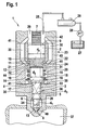
- the single FIGURE shows a fuel injector designed according to the invention.
- FIG. 1 an inventively designed fuel injector is shown.
- the injection valve member 3 is preferably divided into a translator area 4, a guide area 5 and a nozzle needle area 6.
- the diameter d 2 of the translator area 4 of the injection valve member 3 is greater than the one diameter d 3 of the guide portion 5 of the injection valve member 3.
- the diameter d 1 of the nozzle needle portion 6 is preferably smaller than the diameter d 3 of the guide portion 5 of the injection valve member.
- the control of the fuel injector 1 is preferably carried out by means of a piezoelectric actuator 7.
- the control can also be effected by an electromagnet or a hydraulic / mechanical actuator.
- the piezoelectric actuator 7 For closing at least one injection opening 8, the piezoelectric actuator 7 is energized. By energizing the piezocrystals expand and the piezoelectric actuator 7 lengthens. The piezoelectric actuator 7 acts directly on a piezoelectric actuator 7 facing upper end face 9 of the pressure booster 2. As a result, designed as a piston pressure booster 2 is moved in the direction of at least one injection port 8. With a lower end face 10 of the pressure booster 2 limits a booster chamber 11. By the movement of the pressure booster 2 in the direction of the at least one injection port 8, the volume of the booster chamber 11 is reduced. As a result, the pressure in the booster chamber 11 increases.
- At the lower end face 10 of the booster chamber 11 opposite side of the booster chamber 11 is bounded by an end face 12 of the booster section 4 of the injection valve member 3.
- the injection valve member 3 By acting on the end face 12 of the translator portion 4 of the injection valve member 3 hydraulic force the injection valve member 3 is placed on a above the at least one injection port 8 arranged sealing edge 13. As a result, the at least one of the injection opening 8 is closed.
- a spring force which is generated by a spring element 15 received in a spring chamber 14, supports the hydraulic force acting on the end face 12 of the booster region 4 of the injection valve member 3 when the injection valve member 3 is closed.
- the spring element 15 used is preferably a helical spring.
- the spring element 15 rests with one side preferably on a ring 16, which in turn rests on a step 18 formed by an extension 17 between the compiler area 4 and the guide area 5. On the other side, the spring element 15 is preferably supported against an end face 20 of the sleeve 19.
- a biting edge 21 is formed at the end face 20 opposite side of the sleeve 19, a biting edge 21 is formed. Due to the force exerted by the spring element 15 on the end face 20 of the sleeve 19 spring force the biting edge 21 of the sleeve 19 is pressed against a shoulder 22 in the injector 23. This results in a liquid-tight and thus pressure-tight connection between the shoulder 22 of the injector housing 23 and the sleeve 19.
- the inside 24 of the sleeve 19 serves as a guide for the translator section 4 of the injection valve member 3 and at the same time as a lateral boundary and seal of the translator chamber eleventh
- the fuel injector 1 is connected via a feed line 25 to a high pressure accumulator 26.
- the fuel passes from a fuel reservoir 27 via a high pressure pump 28.
- the system pressure of 150 to 2000 bar is provided.
- the fuel flows via the feed line 25 into an annular space 29 surrounding the piezoelectric actuator 7.
- the fuel flows via at least one of the annular space 29 Bypass 30 in the spring chamber 14.
- an annular gap 32 is formed between the outer side 31 of the sleeve 19 and the wall of the injector 23.
- the fuel passes along a bevel 33 in the guide region 5 of the objection valve member 3 in a pressure chamber 34 surrounding the nozzle needle portion 6 of the injection valve member 3.
- a bevel 33 in the guide portion 5 of the injection valve member 3 is a bypass between the guide portion 5 of the injection valve member 3 and a needle guide 35 formed in the nozzle part 36 of the injector 23.
- connection of the spring chamber 14 with the annular space 29 via the at least one bypass 30 and the connection of the annular space 29 with the high-pressure accumulator 26 via the supply line 25 prevail both in the annular space 29 as also in the spring chamber 14 and in the pressure chamber 34 system pressure, which is preferably in the range of 150 to 2000 bar.
- the pressure in the booster chamber 11 changes.
- the pressure in the booster chamber 11 is preferably higher than the system pressure.
- the pressure is preferably lower than the system pressure. Therefore, a pressure-tight connection between the sleeve 19 and the shoulder 22 of the injector is required.
- the current supply required for closing the piezoelectric actuator 7 is terminated.
- the piezocrystals in the piezoactuator 7 contract and the piezoactuator 7 contracts.
- Due to the force acting on the lower end face 10 of the pressure booster 2 hydraulic force of the pressure booster 2 is moved in the direction of the piezoelectric actuator 7.
- the volume of the booster chamber 11 increases, which leads to a decrease in the pressure in the booster chamber 11, compared with the pressure prevailing in the spring chamber 14 system pressure.
- the hydraulic force acting on the end face 12 of the translator area 4 of the injection valve member 3 decreases.
- first pressure stage 38 acts on a at the extension 17 between the compiler area 4 and the guide portion 5 of the injection valve member 3 formed first pressure stage 38, formed on a formed between the guide portion 5 and the nozzle needle portion 6 second pressure stage 39 and on the needle tip of the injection valve member 3 directly formed above the sealing edge 13 third pressure stage 40 a constant hydraulic force, which is directed against the hydraulic force on the end face 12 of the compiler area 4 of the injection valve member 3 opposite.
- the hydraulic force on the first pressure stage 38, the second pressure stage 39 and the third pressure stage 40 is constant, because the spring chamber 14 and the pressure chamber 34 constantly with system pressure are charged.
- a safe operating behavior of the fuel injector 1 is achieved in that the diameter d 4 of the pressure booster 2 is greater than the diameter d 2 of the translator section 4 of the injection valve member 3.
- the diameter of the booster chamber 11 corresponds in the region of the pressure booster 2 the diameter d 4 of the pressure booster second and in the area of the booster region 4 of the injection valve member 3 to the diameter d 2 of the booster region 4. the transition from the diameter of the pressure booster 2 to the diameter of the booster section 4 of the injection valve member 3 is effected by means of paragraph 22nd
- the piezoelectric actuator 7 For closing the at least one injection opening 8, the piezoelectric actuator 7 is energized again. As a result, the piezo crystals expand in the piezoelectric actuator 7 and the piezoelectric actuator 7 lengthens. As a result, the pressure booster 2 moves in the direction of the at least one injection opening 8. In this case, the lower end face 10 of the pressure booster 2 moves into the booster chamber 11 and thus reduces its volume. As a result, the pressure in the booster chamber 11 increases and thus the force acting on the end face 12 of the booster section 4 of the injection valve member 3 hydraulic force.
- Characterized in that the diameter d 3 of the guide portion 5 of the injection valve member 3 is smaller than the diameter d 2 of the compiler region 4 of the injection valve member 3 and further the diameter d 2 of the compiler portion 4 of the injection valve member 3 is smaller than the diameter d 4 of the pressure booster 2, is improves the opening behavior of the fuel injector 1 at low system pressures; by increasing the speed at which the injection valve member 3 opens at low system pressures and thus releasing the at least one injection opening 8 more quickly.
- the injector housing 23 is constructed in several parts.
- the piezoelectric actuator 7 is surrounded by an upper housing part 42
- the pressure booster 2 is of a middle Housing part 43 surrounded, on which also the shoulder 22 is formed.
- the sleeve 19 surrounding the annular gap 32 and the spring chamber 14 are formed by a lower housing part 44.
- the nozzle part 36 connects, in which the needle guide 35, the pressure chamber 34 and the at least one injection port 8 are added.
- the connection points of the housing parts 42, 43, 44, 36 are characterized by division joints 41.
- the connection of the housing parts 42, 43, 44, 36 is preferably carried out positively, for. B. by welding.
Landscapes
- Engineering & Computer Science (AREA)
- Chemical & Material Sciences (AREA)
- Combustion & Propulsion (AREA)
- Mechanical Engineering (AREA)
- General Engineering & Computer Science (AREA)
- Fuel-Injection Apparatus (AREA)
Claims (10)
- Injecteur de carburant pour moteurs à combustion interne avec un accumulateur haute pression (26), avec un organe de soupape d'injection (3) étagé dans une région de multiplication (4), une région de guidage (5) et une région de pointeau (6), la région de multiplication (4) pouvant être introduite avec une surface frontale (12) dans un espace de multiplication (11) pour ouvrir au moins une ouverture d'injection (8), et du côté opposé à la surface frontale (12) de la région de multiplication (4) de l'organe de soupape d'injection (3), l'espace de multiplication (11) est limité par une surface frontale inférieure (10) d'un multiplicateur de pression (2), le multiplicateur de pression (2) étant commandé directement par un actionneur (7), un élément de ressort (15) étant reçu autour de la région de multiplication (4) de l'organe de soupape d'injection (3), lequel s'appuie d'un côté sur une bague (16) disposée à la transition de la région de multiplication (4) à une région de guidage (5) de l'organe de soupape d'injection (3) et de l'autre côté contre une douille (19) entourant la région de multiplication (4) de l'organe de soupape d'injection (3), le carburant parvenant de l'accumulateur haute pression (26) par le biais d'au moins une dérivation (30) dans un espace de ressort (14) entourant la région de multiplication (4) de l'organe de soupape d'injection (3), et entre la paroi extérieure (31) de la douille (19) et le boîtier d'injecteur (23) étant formée une fente annulaire (32), par le biais de laquelle l'au moins une dérivation (30) est connectée à l'espace de ressort (14), caractérisé en ce que la douille (19) est pourvue du côté opposé à l'élément de ressort (15) d'une arête d'attaque (21) qui est pressée contre le boîtier d'injecteur (23) et qui limite ainsi latéralement l'espace de multiplication (11).
- Injecteur de carburant selon la revendication 1, caractérisé en ce que le carburant parvient en outre depuis l'espace de ressort (14) et de là par le biais d'au moins un biseau (33), dans la région de guidage (5) de l'organe de soupape d'injection (3), dans un espace de pression (34) entourant la région de pointeau (6).
- Injecteur de carburant selon la revendication 1, caractérisé en ce que l'élément de ressort (15) est un ressort spiral.
- Injecteur de carburant selon la revendication 1, caractérisé en ce que l'actionneur est un actionneur piézoélectrique (7).
- Injecteur de carburant selon la revendication 1, caractérisé en ce qu'un élargissement (17) est réalisé à la transition entre la région de multiplication (4) et la région de guidage (5) de l'organe de soupape d'injection (3).
- Injecteur de carburant selon la revendication 5, caractérisé en ce que le côté de l'élargissement (17) tourné vers la chambre de combustion est un premier étage de pression (38).
- Injecteur de carburant selon la revendication 1, caractérisé en ce que la transition de la région de guidage (5) à la région de pointeau (6) de l'organe de soupape d'injection (3) agit comme un deuxième étage de pression (39).
- Injecteur de carburant selon la revendication 1, caractérisé en ce qu'un troisième étage de pression (40) est réalisé dans la région de pointeau (6) de l'organe de soupape d'injection (3).
- Injecteur de carburant selon les revendications 1 et 5, caractérisé en ce que la bague (16) repose sur un étage (18) de l'élargissement (17) tourné vers la région de multiplication (4) de l'organe de soupape d'injection (3).
- Injecteur de carburant selon l'une quelconque des revendications 1 à 9, caractérisé en ce que le boîtier d'injecteur (23) comprend une partie de boîtier supérieure (42), une partie de boîtier centrale (43), une partie de boîtier inférieure (44) et une partie de buse (36).
Applications Claiming Priority (2)
| Application Number | Priority Date | Filing Date | Title |
|---|---|---|---|
| DE200410002309 DE102004002309A1 (de) | 2004-01-16 | 2004-01-16 | Kraftstoffinjektor mit direkter Nadelstreuerung |
| PCT/DE2004/002553 WO2005068820A1 (fr) | 2004-01-16 | 2004-11-19 | Injecteur de carburant a commande de pointeau directe |
Publications (2)
| Publication Number | Publication Date |
|---|---|
| EP1709319A1 EP1709319A1 (fr) | 2006-10-11 |
| EP1709319B1 true EP1709319B1 (fr) | 2010-08-11 |
Family
ID=34716617
Family Applications (1)
| Application Number | Title | Priority Date | Filing Date |
|---|---|---|---|
| EP04802766A Expired - Lifetime EP1709319B1 (fr) | 2004-01-16 | 2004-11-19 | Injecteur de carburant a commande de pointeau directe |
Country Status (3)
| Country | Link |
|---|---|
| EP (1) | EP1709319B1 (fr) |
| DE (2) | DE102004002309A1 (fr) |
| WO (1) | WO2005068820A1 (fr) |
Families Citing this family (8)
| Publication number | Priority date | Publication date | Assignee | Title |
|---|---|---|---|---|
| DE102004005452B4 (de) * | 2004-02-04 | 2014-01-09 | Robert Bosch Gmbh | Düsenhalterkombination mit direktgesteuertem Einspritzventilglied |
| DE102004044462A1 (de) * | 2004-09-15 | 2006-03-30 | Robert Bosch Gmbh | Steuerventil für einen Injektor |
| DE102006012078A1 (de) * | 2005-11-15 | 2007-05-16 | Bosch Gmbh Robert | Kraftstoff-Einspritzvorrichtung für eine Brennkraftmaschine mit Kraftstoff-Direkteinspritzung |
| DE102006053126A1 (de) * | 2006-11-10 | 2008-05-15 | Robert Bosch Gmbh | Kraftstoff-Einspritzvorrichtung |
| DE102007001363A1 (de) | 2007-01-09 | 2008-07-10 | Robert Bosch Gmbh | Injektor zum Einspritzen von Kraftstoff in Brennräume von Brennkraftmaschinen |
| DE102009000830A1 (de) * | 2009-02-13 | 2010-08-19 | Robert Bosch Gmbh | Kraftstoffinjektor mit längeneinstellbarem Kopplerkonzept |
| DE102009045348A1 (de) * | 2009-10-06 | 2011-04-07 | Robert Bosch Gmbh | Kraftstoffeinspritzventil und dessen Herstellung |
| DE102012005319A1 (de) * | 2012-03-19 | 2013-09-19 | L'orange Gmbh | Injektorbaugruppe |
Family Cites Families (6)
| Publication number | Priority date | Publication date | Assignee | Title |
|---|---|---|---|---|
| JP2636410B2 (ja) * | 1989-03-27 | 1997-07-30 | トヨタ自動車株式会社 | 内燃機関用燃料供給ポンプ制御装置 |
| DE19642441A1 (de) * | 1996-10-15 | 1998-04-16 | Bosch Gmbh Robert | Verfahren zum Betätigen eines Kraftstoffeinspritzventils für Brennkraftmaschinen |
| DE10203657A1 (de) * | 2002-01-30 | 2003-08-28 | Bosch Gmbh Robert | Brennstoffeinspritzventil |
| DE10213858A1 (de) * | 2002-03-27 | 2003-10-30 | Bosch Gmbh Robert | Brennstoffeinspritzventil |
| DE10232193A1 (de) * | 2002-07-16 | 2004-02-05 | Robert Bosch Gmbh | Brennstoffeinspritzventil |
| DE10343086A1 (de) * | 2003-09-17 | 2005-05-19 | Robert Bosch Gmbh | Brenntoffeinspritzventil |
-
2004
- 2004-01-16 DE DE200410002309 patent/DE102004002309A1/de not_active Withdrawn
- 2004-11-19 WO PCT/DE2004/002553 patent/WO2005068820A1/fr not_active Ceased
- 2004-11-19 DE DE502004011535T patent/DE502004011535D1/de not_active Expired - Lifetime
- 2004-11-19 EP EP04802766A patent/EP1709319B1/fr not_active Expired - Lifetime
Also Published As
| Publication number | Publication date |
|---|---|
| WO2005068820A1 (fr) | 2005-07-28 |
| EP1709319A1 (fr) | 2006-10-11 |
| DE502004011535D1 (de) | 2010-09-23 |
| DE102004002309A1 (de) | 2005-08-04 |
Similar Documents
| Publication | Publication Date | Title |
|---|---|---|
| EP2052148B1 (fr) | Injecteur de carburant avec commande directe du pointeau et servosoupape d'assistance | |
| EP1613856B1 (fr) | Injecteur de carburant comportant un transmetteur de pression commande par une soupape asservie | |
| EP1440237B1 (fr) | Soupape pour commander le passage de liquides | |
| EP2054614B1 (fr) | Injecteur de carburant comprenant un rappel de piston d'un piston multiplicateur de pression | |
| EP1554488B1 (fr) | Dispositif d'injection de carburant a pression multipliee, pourvu d'une conduite de commande interne | |
| EP1520099B1 (fr) | Injecteur de carburant a multiplicateur de pression a reduction de pression rapide lors de l'injection | |
| WO2002084106A1 (fr) | Soupape pour commander le passage de fluides | |
| DE102005009147A1 (de) | Kraftstoffinjektor für Verbrennungskraftmaschinen | |
| WO2004104403A1 (fr) | Soupape permettant de commander le passage de liquides | |
| EP1692392B1 (fr) | Injecteur de carburant a commande de pointeau directe | |
| EP1709319B1 (fr) | Injecteur de carburant a commande de pointeau directe | |
| DE10335059A1 (de) | Schaltventil für einen Kraftstoffinjektor mit Druckübersetzer | |
| EP2205852B1 (fr) | Procédé de commande d'un moteur à combustion avec un injecteur à combustible | |
| EP1682769B1 (fr) | Injecteur de carburant dote d'un element de soupape d'injection en plusieurs parties, en commande directe | |
| EP2156050B1 (fr) | Système d'amplification de pression pour au moins un injecteur de carburant | |
| DE19949527A1 (de) | Injektor für ein Kraftstoffeinspritzsystem für Brennkraftmaschinen mit in den Ventilsteuerraum ragender Düsennadel | |
| WO2004070201A1 (fr) | Systeme d'injection de carburant pour moteur a combustion interne | |
| EP1872008B1 (fr) | Injecteur de carburant s'ouvrant a deux niveaux | |
| WO2002020978A1 (fr) | Soupape a translation hydraulique | |
| EP2136067A1 (fr) | Injecteur de carburant | |
| EP1825137B1 (fr) | Injecteur de carburant | |
| DE102008002415A1 (de) | Kraftstoffinjektor | |
| EP2133552B1 (fr) | Injecteur de carburant | |
| DE102006050164A1 (de) | Kraftstoffinjektor mit hydraulischer Übersetzung | |
| EP2199590A1 (fr) | Injecteur de carburant |
Legal Events
| Date | Code | Title | Description |
|---|---|---|---|
| PUAI | Public reference made under article 153(3) epc to a published international application that has entered the european phase |
Free format text: ORIGINAL CODE: 0009012 |
|
| 17P | Request for examination filed |
Effective date: 20060816 |
|
| AK | Designated contracting states |
Kind code of ref document: A1 Designated state(s): DE FR GB IT |
|
| DAX | Request for extension of the european patent (deleted) | ||
| RBV | Designated contracting states (corrected) |
Designated state(s): DE FR GB IT |
|
| 17Q | First examination report despatched |
Effective date: 20081204 |
|
| GRAP | Despatch of communication of intention to grant a patent |
Free format text: ORIGINAL CODE: EPIDOSNIGR1 |
|
| GRAS | Grant fee paid |
Free format text: ORIGINAL CODE: EPIDOSNIGR3 |
|
| GRAA | (expected) grant |
Free format text: ORIGINAL CODE: 0009210 |
|
| AK | Designated contracting states |
Kind code of ref document: B1 Designated state(s): DE FR GB IT |
|
| REG | Reference to a national code |
Ref country code: GB Ref legal event code: FG4D Free format text: NOT ENGLISH |
|
| REF | Corresponds to: |
Ref document number: 502004011535 Country of ref document: DE Date of ref document: 20100923 Kind code of ref document: P |
|
| PLBE | No opposition filed within time limit |
Free format text: ORIGINAL CODE: 0009261 |
|
| STAA | Information on the status of an ep patent application or granted ep patent |
Free format text: STATUS: NO OPPOSITION FILED WITHIN TIME LIMIT |
|
| 26N | No opposition filed |
Effective date: 20110512 |
|
| GBPC | Gb: european patent ceased through non-payment of renewal fee |
Effective date: 20101119 |
|
| REG | Reference to a national code |
Ref country code: DE Ref legal event code: R097 Ref document number: 502004011535 Country of ref document: DE Effective date: 20110512 |
|
| PG25 | Lapsed in a contracting state [announced via postgrant information from national office to epo] |
Ref country code: GB Free format text: LAPSE BECAUSE OF NON-PAYMENT OF DUE FEES Effective date: 20101119 |
|
| PGFP | Annual fee paid to national office [announced via postgrant information from national office to epo] |
Ref country code: FR Payment date: 20141118 Year of fee payment: 11 |
|
| PGFP | Annual fee paid to national office [announced via postgrant information from national office to epo] |
Ref country code: IT Payment date: 20141125 Year of fee payment: 11 |
|
| PG25 | Lapsed in a contracting state [announced via postgrant information from national office to epo] |
Ref country code: IT Free format text: LAPSE BECAUSE OF NON-PAYMENT OF DUE FEES Effective date: 20151119 |
|
| REG | Reference to a national code |
Ref country code: FR Ref legal event code: ST Effective date: 20160729 |
|
| PG25 | Lapsed in a contracting state [announced via postgrant information from national office to epo] |
Ref country code: FR Free format text: LAPSE BECAUSE OF NON-PAYMENT OF DUE FEES Effective date: 20151130 |
|
| PGFP | Annual fee paid to national office [announced via postgrant information from national office to epo] |
Ref country code: DE Payment date: 20180125 Year of fee payment: 14 |
|
| REG | Reference to a national code |
Ref country code: DE Ref legal event code: R119 Ref document number: 502004011535 Country of ref document: DE |
|
| PG25 | Lapsed in a contracting state [announced via postgrant information from national office to epo] |
Ref country code: DE Free format text: LAPSE BECAUSE OF NON-PAYMENT OF DUE FEES Effective date: 20190601 |