EP1709723B1 - Systeme de retention de porte-balais integre - Google Patents
Systeme de retention de porte-balais integre Download PDFInfo
- Publication number
- EP1709723B1 EP1709723B1 EP05705436A EP05705436A EP1709723B1 EP 1709723 B1 EP1709723 B1 EP 1709723B1 EP 05705436 A EP05705436 A EP 05705436A EP 05705436 A EP05705436 A EP 05705436A EP 1709723 B1 EP1709723 B1 EP 1709723B1
- Authority
- EP
- European Patent Office
- Prior art keywords
- brush
- holder
- motor
- commutator
- housing portion
- Prior art date
- Legal status (The legal status is an assumption and is not a legal conclusion. Google has not performed a legal analysis and makes no representation as to the accuracy of the status listed.)
- Expired - Lifetime
Links
- 230000014759 maintenance of location Effects 0.000 title 1
- 230000006835 compression Effects 0.000 claims description 7
- 238000007906 compression Methods 0.000 claims description 7
- 239000012777 electrically insulating material Substances 0.000 claims description 2
- 238000003780 insertion Methods 0.000 claims description 2
- 230000037431 insertion Effects 0.000 claims description 2
- OKTJSMMVPCPJKN-UHFFFAOYSA-N Carbon Chemical compound [C] OKTJSMMVPCPJKN-UHFFFAOYSA-N 0.000 description 3
- 229910052799 carbon Inorganic materials 0.000 description 3
- 238000010276 construction Methods 0.000 description 2
- 229920001971 elastomer Polymers 0.000 description 2
- 229920001342 Bakelite® Polymers 0.000 description 1
- RYGMFSIKBFXOCR-UHFFFAOYSA-N Copper Chemical compound [Cu] RYGMFSIKBFXOCR-UHFFFAOYSA-N 0.000 description 1
- 230000000712 assembly Effects 0.000 description 1
- 238000000429 assembly Methods 0.000 description 1
- 239000004637 bakelite Substances 0.000 description 1
- 239000004020 conductor Substances 0.000 description 1
- 229910052802 copper Inorganic materials 0.000 description 1
- 239000010949 copper Substances 0.000 description 1
- 238000002788 crimping Methods 0.000 description 1
- 230000000994 depressogenic effect Effects 0.000 description 1
- 230000004064 dysfunction Effects 0.000 description 1
- 238000002955 isolation Methods 0.000 description 1
- 238000012423 maintenance Methods 0.000 description 1
- 230000013011 mating Effects 0.000 description 1
- 239000007769 metal material Substances 0.000 description 1
- 239000000203 mixture Substances 0.000 description 1
- 230000000737 periodic effect Effects 0.000 description 1
- 238000005476 soldering Methods 0.000 description 1
- 239000007858 starting material Substances 0.000 description 1
Images






Classifications
-
- H—ELECTRICITY
- H01—ELECTRIC ELEMENTS
- H01R—ELECTRICALLY-CONDUCTIVE CONNECTIONS; STRUCTURAL ASSOCIATIONS OF A PLURALITY OF MUTUALLY-INSULATED ELECTRICAL CONNECTING ELEMENTS; COUPLING DEVICES; CURRENT COLLECTORS
- H01R39/00—Rotary current collectors, distributors or interrupters
- H01R39/02—Details for dynamo electric machines
- H01R39/38—Brush holders
- H01R39/385—Means for mechanical fixation of the brush holder
-
- H—ELECTRICITY
- H01—ELECTRIC ELEMENTS
- H01R—ELECTRICALLY-CONDUCTIVE CONNECTIONS; STRUCTURAL ASSOCIATIONS OF A PLURALITY OF MUTUALLY-INSULATED ELECTRICAL CONNECTING ELEMENTS; COUPLING DEVICES; CURRENT COLLECTORS
- H01R39/00—Rotary current collectors, distributors or interrupters
- H01R39/02—Details for dynamo electric machines
- H01R39/38—Brush holders
- H01R39/41—Brush holders cartridge type
-
- H—ELECTRICITY
- H02—GENERATION; CONVERSION OR DISTRIBUTION OF ELECTRIC POWER
- H02K—DYNAMO-ELECTRIC MACHINES
- H02K5/00—Casings; Enclosures; Supports
- H02K5/04—Casings or enclosures characterised by the shape, form or construction thereof
- H02K5/14—Means for supporting or protecting brushes or brush holders
- H02K5/143—Means for supporting or protecting brushes or brush holders for cooperation with commutators
- H02K5/148—Slidably supported brushes
-
- H—ELECTRICITY
- H02—GENERATION; CONVERSION OR DISTRIBUTION OF ELECTRIC POWER
- H02K—DYNAMO-ELECTRIC MACHINES
- H02K5/00—Casings; Enclosures; Supports
- H02K5/04—Casings or enclosures characterised by the shape, form or construction thereof
- H02K5/22—Auxiliary parts of casings not covered by groups H02K5/06-H02K5/20, e.g. shaped to form connection boxes or terminal boxes
- H02K5/225—Terminal boxes or connection arrangements
Landscapes
- Engineering & Computer Science (AREA)
- Power Engineering (AREA)
- Motor Or Generator Current Collectors (AREA)
Abstract
Claims (9)
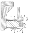
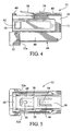
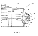
- Ensemble de porte-balais de moteur électrique qui est du type qui présente un collecteur tournant, qui est tourillonné dans une première partie de logement de moteur (10, 18), ledit ensemble comprenant :→ une seconde partie de logement de moteur (64, 72, 74, 76) configurée de manière à être connectée par accouplement à la première partie de logement de moteur (10, 18) et présentant à l'intérieur au moins une poche de réception de balai (46), ladite poche (46) étant formée par une structure de ladite seconde partie de logement de moteur (64, 72, 74, 76) qui définit une surface de support (64, 76) sur l'un de ses côtés et une partie de pont (72) sur le côté opposé ;→ un balai allongé (34) qui présente des première et seconde extrémités, dans lequel ladite première extrémité (78) est configurée de manière à être couplée à un élément de sollicitation élastique (80) et ladite seconde extrémité est configurée de manière à entrer en contact avec le collecteur du moteur ;→ au moins un porte-balais amovible (12, 16) présentant une première extrémité ouverte (36) configurée de manière à recevoir à l'intérieur ledit balai (34) et à s'adapter dans ladite poche (46), et une seconde extrémité ouverte (77) qui permet audit balai (34) de s'étendre de là vers l'extérieur de manière à entrer en contact avec le collecteur du moteur ;→ un élément de sollicitation élastique (80) couplé audit balai (34) ; et→ un embout (84) couplé à la première extrémité ouverte (36) et configuré de manière à venir en butée avec ledit élément de sollicitation élastique (80) de façon à solliciter de manière élastique le balai (34) vers le collecteur du moteur ; dans lequel ledit porte-balais (12, 16) est agencé de telle sorte que ledit balai (34) puisse être retiré du porte-balais (12, 16) lors du retrait dudit embout (84) ;caractérisé en ce que ledit porte-balais (12, 16) comprend en outre une patte de verrouillage (54) sollicitée de manière élastique vers le haut à partir d'une surface supérieure (40) de celle-ci de manière à venir en prise avec ladite partie de pont (72) de ladite seconde partie de logement de moteur (64, 72, 74, 76).
- Ensemble de porte-balais selon la revendication 1, comprenant en outre deux porte-balais amovibles (12, 16), chacun desdits porte-balais amovibles étant configuré de manière à recevoir à l'intérieur un balai (34).
- Ensemble de porte-balais selon la revendication 1, dans lequel ladite première partie d'extrémité (78) dudit balai (34) est configurée en outre de manière à être cylindrique.
- Ensemble de porte-balais selon la revendication 1, dans lequel ladite seconde partie de logement (64, 72, 74, 76) comprend un matériau isolant de manière électrique.
- Ensemble de porte-balais selon la revendication 1, dans lequel ledit au moins un porte-balais (12, 16) comprend en outre une partie de base isolante (44).
- Ensemble de porte-balais selon la revendication 5, dans lequel ladite partie de base isolante (44) comprend une paire d'épaulements (52a, 52a) de manière à limiter le déplacement du porte-balais (12, 16) au cours d'une insertion.
- Ensemble de porte-balais selon la revendication 1, dans lequel ledit élément de sollicitation élastique (80) comprend un ressort de compression (80) interposé entre ledit embout (84) et ladite première partie d'extrémité (78) destiné à solliciter de manière élastique ledit balai (34) vers le collecteur.
- Ensemble de porte-balais selon la revendication 3, dans lequel ledit élément de sollicitation élastique est couplé à ladite partie d'extrémité cylindrique (78).
- Ensemble de porte-balais selon la revendication 1, dans lequel une patte de contact (58) s'étend vers le haut à partir de ladite surface supérieure (40) de façon à venir en prise de manière électrique avec le moteur.
Applications Claiming Priority (3)
| Application Number | Priority Date | Filing Date | Title |
|---|---|---|---|
| US53746604P | 2004-01-16 | 2004-01-16 | |
| US10/990,571 US7049727B2 (en) | 2004-01-16 | 2004-11-17 | Integrated brush-holder retention system |
| PCT/US2005/000776 WO2005074101A1 (fr) | 2004-01-16 | 2005-01-11 | Systeme de retention de porte-balais integre |
Publications (2)
| Publication Number | Publication Date |
|---|---|
| EP1709723A1 EP1709723A1 (fr) | 2006-10-11 |
| EP1709723B1 true EP1709723B1 (fr) | 2010-04-21 |
Family
ID=34753084
Family Applications (1)
| Application Number | Title | Priority Date | Filing Date |
|---|---|---|---|
| EP05705436A Expired - Lifetime EP1709723B1 (fr) | 2004-01-16 | 2005-01-11 | Systeme de retention de porte-balais integre |
Country Status (7)
| Country | Link |
|---|---|
| US (1) | US7049727B2 (fr) |
| EP (1) | EP1709723B1 (fr) |
| JP (1) | JP4638884B2 (fr) |
| CN (1) | CN1910804B (fr) |
| CA (1) | CA2553451A1 (fr) |
| DE (1) | DE602005020740D1 (fr) |
| WO (1) | WO2005074101A1 (fr) |
Cited By (1)
| Publication number | Priority date | Publication date | Assignee | Title |
|---|---|---|---|---|
| FR2983660A1 (fr) * | 2011-12-06 | 2013-06-07 | Bosch Gmbh Robert | Machine electrique |
Families Citing this family (17)
| Publication number | Priority date | Publication date | Assignee | Title |
|---|---|---|---|---|
| EP2128964A3 (fr) | 2001-12-18 | 2017-05-17 | Cutsforth Products Inc. | Support de balais adapté pour être retiré sans arrêter la machine |
| TWM286734U (en) * | 2005-08-10 | 2006-02-01 | Rexon Ind Corp Ltd | Laser labeling apparatus for circular saw machine |
| US7531938B2 (en) * | 2006-03-13 | 2009-05-12 | Mcmillan Electric Company | Insertable brush holder assembly for electric motor |
| US20080084133A1 (en) * | 2006-10-06 | 2008-04-10 | Steven Burton | Dynamoelectric machine brush and method |
| US7466056B2 (en) * | 2006-10-06 | 2008-12-16 | Remi International, Inc | Dynamoelectric machine brush holder assembly and method |
| US7705512B2 (en) * | 2006-10-06 | 2010-04-27 | Remy International, Inc. | Dynamoelectric machine conductor |
| US7696666B2 (en) * | 2006-10-06 | 2010-04-13 | Remy Technologies, L.L.C. | Dynamoelectric machine grommet |
| DE102007047648A1 (de) * | 2007-10-05 | 2009-04-09 | BSH Bosch und Siemens Hausgeräte GmbH | Bürstenanordnung und elektrische Maschine, insbesondere elektrisches Hausgerät |
| US8922092B2 (en) | 2011-03-07 | 2014-12-30 | Cutsforth, Inc. | Brush holder assembly with quick disconnect terminal |
| DE102011089775A1 (de) * | 2011-12-23 | 2013-06-27 | Robert Bosch Gmbh | Kommutatormotor |
| CN103427277A (zh) * | 2012-05-18 | 2013-12-04 | 海门市华联电碳有限公司 | 角向磨光机用碳刷 |
| JP6046510B2 (ja) * | 2013-02-08 | 2016-12-14 | リョービ株式会社 | 縦型電動工具 |
| CN205583897U (zh) * | 2016-03-07 | 2016-09-14 | 德昌电机(深圳)有限公司 | 电刷装置、电机及液泵 |
| EP3764485A1 (fr) * | 2019-07-12 | 2021-01-13 | Ratier-Figeac SAS | Ensemble de brosse |
| US12015229B2 (en) | 2020-11-04 | 2024-06-18 | Cutsforth, Inc. | Brush holder assembly |
| CA3198779A1 (fr) | 2020-12-01 | 2022-06-09 | Robert S. Cutsforth | Ensemble balai |
| CN120955428B (zh) * | 2025-10-17 | 2026-02-10 | 大连宜顺精密制造股份有限公司 | 高电压电能传输用电刷总成及高电压电能传输系统 |
Family Cites Families (10)
| Publication number | Priority date | Publication date | Assignee | Title |
|---|---|---|---|---|
| US3784856A (en) * | 1972-07-31 | 1974-01-08 | Gen Electric | Brush holder assembly |
| JPS5822061U (ja) * | 1981-07-28 | 1983-02-10 | ブラザー工業株式会社 | モ−タにおけるブラシホルダ−蓋体取付装置 |
| IT8553611V0 (it) | 1985-07-19 | 1985-07-19 | Magneti Marelli Spa | Perfezionamenti nei portaspazzole per macchine elettriche a collettore particolarmente per motori di avviamento |
| JPH02206341A (ja) * | 1989-02-03 | 1990-08-16 | Nippon Danfuosu Seizo Kk | 直流モータ及びそのブラシアダプタ |
| JPH0393444A (ja) * | 1989-09-04 | 1991-04-18 | Matsushita Electric Ind Co Ltd | ブラシ組立品 |
| US5793141A (en) * | 1995-06-28 | 1998-08-11 | Milwaukee Electric Tool Corp. | Plug-in modular brush cartridge |
| JP2000116072A (ja) * | 1998-10-01 | 2000-04-21 | Makita Corp | ブラシホルダの取付構造 |
| JP3515425B2 (ja) * | 1999-05-24 | 2004-04-05 | 株式会社マキタ | モータの収容構造 |
| GB0003134D0 (en) * | 2000-02-12 | 2000-04-05 | Johnson Electric Sa | Brush holder assembly |
| DE20209292U1 (de) | 2002-06-14 | 2003-10-16 | Scintilla Ag, Solothurn | Elektromotor für Handwerkzeugmaschine |
-
2004
- 2004-11-17 US US10/990,571 patent/US7049727B2/en not_active Expired - Lifetime
-
2005
- 2005-01-11 EP EP05705436A patent/EP1709723B1/fr not_active Expired - Lifetime
- 2005-01-11 CA CA002553451A patent/CA2553451A1/fr not_active Abandoned
- 2005-01-11 WO PCT/US2005/000776 patent/WO2005074101A1/fr not_active Ceased
- 2005-01-11 CN CN2005800024575A patent/CN1910804B/zh not_active Expired - Lifetime
- 2005-01-11 JP JP2006549508A patent/JP4638884B2/ja not_active Expired - Lifetime
- 2005-01-11 DE DE602005020740T patent/DE602005020740D1/de not_active Expired - Lifetime
Cited By (1)
| Publication number | Priority date | Publication date | Assignee | Title |
|---|---|---|---|---|
| FR2983660A1 (fr) * | 2011-12-06 | 2013-06-07 | Bosch Gmbh Robert | Machine electrique |
Also Published As
| Publication number | Publication date |
|---|---|
| US7049727B2 (en) | 2006-05-23 |
| DE602005020740D1 (de) | 2010-06-02 |
| CN1910804B (zh) | 2010-10-13 |
| JP2007518388A (ja) | 2007-07-05 |
| CN1910804A (zh) | 2007-02-07 |
| US20050156477A1 (en) | 2005-07-21 |
| EP1709723A1 (fr) | 2006-10-11 |
| JP4638884B2 (ja) | 2011-02-23 |
| CA2553451A1 (fr) | 2005-08-11 |
| WO2005074101A1 (fr) | 2005-08-11 |
Similar Documents
| Publication | Publication Date | Title |
|---|---|---|
| US7049727B2 (en) | Integrated brush-holder retention system | |
| EP0236254B1 (fr) | Porte-balais pour machines dynamo-électriques | |
| US6445097B1 (en) | Method for assembling and electrical connector assembly for a power tool | |
| US5148073A (en) | Wiring device in direct current machine | |
| US5753993A (en) | Adjusting apparatus for carbon brushes on an electric motor | |
| CN110198816B (zh) | 切断工具 | |
| US6909218B2 (en) | End cap and brush box assembly | |
| US7531938B2 (en) | Insertable brush holder assembly for electric motor | |
| US8487503B2 (en) | Hand power tool with brush motor | |
| US20080101100A1 (en) | Kit of power tools | |
| US7229301B2 (en) | Motor-switch arrangement for a hand-held power tool | |
| US6246144B1 (en) | Carbon brush holders or cards | |
| KR101073082B1 (ko) | 전기모터의 브러시 홀딩장치 | |
| US6225717B1 (en) | Electromotor | |
| US20170155300A1 (en) | Electric motor brush apparatus and method | |
| WO1999028981A1 (fr) | Produit comprenant une pile rechargeable maintenue de façon mecaniquement stable facile a retirer | |
| MXPA04011447A (es) | Agrupamiento de transmision de corriente. | |
| GB2232011A (en) | Terminal adapter in an electric motor | |
| MXPA06008090A (en) | Integrated brush-holder retention system | |
| KR20170081960A (ko) | 탈착형 브러쉬를 포함하는 차량용 교류발전기의 레귤레이터 | |
| EP1150415A2 (fr) | Couvercle de balais pour démarreur | |
| KR200260354Y1 (ko) | 전동공구용 트리거 스위치 | |
| JP2005223974A (ja) | 直流モータにおけるブラシの取付け構造 | |
| JPH10269879A (ja) | ヒューズフリー遮断器用電源クリップ装置 | |
| KR20000017040U (ko) | 모터의 브러시 홀더 |
Legal Events
| Date | Code | Title | Description |
|---|---|---|---|
| PUAI | Public reference made under article 153(3) epc to a published international application that has entered the european phase |
Free format text: ORIGINAL CODE: 0009012 |
|
| 17P | Request for examination filed |
Effective date: 20060713 |
|
| AK | Designated contracting states |
Kind code of ref document: A1 Designated state(s): DE FR GB IT |
|
| RIN1 | Information on inventor provided before grant (corrected) |
Inventor name: BOCKA, RALF Inventor name: WASCOW, JOSEPH, Z. |
|
| 17Q | First examination report despatched |
Effective date: 20070212 |
|
| DAX | Request for extension of the european patent (deleted) | ||
| RBV | Designated contracting states (corrected) |
Designated state(s): DE FR GB IT |
|
| GRAP | Despatch of communication of intention to grant a patent |
Free format text: ORIGINAL CODE: EPIDOSNIGR1 |
|
| GRAS | Grant fee paid |
Free format text: ORIGINAL CODE: EPIDOSNIGR3 |
|
| GRAA | (expected) grant |
Free format text: ORIGINAL CODE: 0009210 |
|
| AK | Designated contracting states |
Kind code of ref document: B1 Designated state(s): DE FR GB IT |
|
| REG | Reference to a national code |
Ref country code: GB Ref legal event code: FG4D |
|
| REF | Corresponds to: |
Ref document number: 602005020740 Country of ref document: DE Date of ref document: 20100602 Kind code of ref document: P |
|
| PLBE | No opposition filed within time limit |
Free format text: ORIGINAL CODE: 0009261 |
|
| STAA | Information on the status of an ep patent application or granted ep patent |
Free format text: STATUS: NO OPPOSITION FILED WITHIN TIME LIMIT |
|
| 26N | No opposition filed |
Effective date: 20110124 |
|
| PG25 | Lapsed in a contracting state [announced via postgrant information from national office to epo] |
Ref country code: IT Free format text: LAPSE BECAUSE OF FAILURE TO SUBMIT A TRANSLATION OF THE DESCRIPTION OR TO PAY THE FEE WITHIN THE PRESCRIBED TIME-LIMIT Effective date: 20100421 |
|
| REG | Reference to a national code |
Ref country code: FR Ref legal event code: PLFP Year of fee payment: 12 |
|
| REG | Reference to a national code |
Ref country code: FR Ref legal event code: PLFP Year of fee payment: 13 |
|
| REG | Reference to a national code |
Ref country code: FR Ref legal event code: PLFP Year of fee payment: 14 |
|
| PGFP | Annual fee paid to national office [announced via postgrant information from national office to epo] |
Ref country code: DE Payment date: 20240322 Year of fee payment: 20 Ref country code: GB Payment date: 20240124 Year of fee payment: 20 |
|
| PGFP | Annual fee paid to national office [announced via postgrant information from national office to epo] |
Ref country code: FR Payment date: 20240124 Year of fee payment: 20 |
|
| REG | Reference to a national code |
Ref country code: DE Ref legal event code: R071 Ref document number: 602005020740 Country of ref document: DE |
|
| REG | Reference to a national code |
Ref country code: GB Ref legal event code: PE20 Expiry date: 20250110 |
|
| PG25 | Lapsed in a contracting state [announced via postgrant information from national office to epo] |
Ref country code: GB Free format text: LAPSE BECAUSE OF EXPIRATION OF PROTECTION Effective date: 20250110 |