EP1710029A2 - Lixiviation pour noyau - Google Patents
Lixiviation pour noyau Download PDFInfo
- Publication number
- EP1710029A2 EP1710029A2 EP06251175A EP06251175A EP1710029A2 EP 1710029 A2 EP1710029 A2 EP 1710029A2 EP 06251175 A EP06251175 A EP 06251175A EP 06251175 A EP06251175 A EP 06251175A EP 1710029 A2 EP1710029 A2 EP 1710029A2
- Authority
- EP
- European Patent Office
- Prior art keywords
- leaching
- core
- tank
- arrangement
- leaching fluid
- Prior art date
- Legal status (The legal status is an assumption and is not a legal conclusion. Google has not performed a legal analysis and makes no representation as to the accuracy of the status listed.)
- Granted
Links
- 238000002386 leaching Methods 0.000 title claims abstract description 181
- 238000000034 method Methods 0.000 claims abstract description 45
- 238000013019 agitation Methods 0.000 claims abstract description 22
- 230000032683 aging Effects 0.000 claims abstract description 4
- 239000012530 fluid Substances 0.000 claims description 98
- 230000003628 erosive effect Effects 0.000 claims description 19
- 239000007921 spray Substances 0.000 claims description 5
- 238000007598 dipping method Methods 0.000 claims description 3
- 238000005406 washing Methods 0.000 claims description 3
- 238000007605 air drying Methods 0.000 claims description 2
- 230000008569 process Effects 0.000 abstract description 33
- 230000000694 effects Effects 0.000 abstract description 14
- 239000000243 solution Substances 0.000 description 30
- 239000002195 soluble material Substances 0.000 description 8
- 229920006395 saturated elastomer Polymers 0.000 description 7
- 238000001746 injection moulding Methods 0.000 description 4
- 230000033001 locomotion Effects 0.000 description 4
- 238000004519 manufacturing process Methods 0.000 description 4
- 238000013459 approach Methods 0.000 description 3
- 238000000465 moulding Methods 0.000 description 3
- 239000003153 chemical reaction reagent Substances 0.000 description 2
- 230000007613 environmental effect Effects 0.000 description 2
- 238000010438 heat treatment Methods 0.000 description 2
- 239000003595 mist Substances 0.000 description 2
- 238000012545 processing Methods 0.000 description 2
- 238000005201 scrubbing Methods 0.000 description 2
- 239000000126 substance Substances 0.000 description 2
- 239000000725 suspension Substances 0.000 description 2
- 239000002699 waste material Substances 0.000 description 2
- 230000004075 alteration Effects 0.000 description 1
- 230000008901 benefit Effects 0.000 description 1
- 230000015572 biosynthetic process Effects 0.000 description 1
- 230000015556 catabolic process Effects 0.000 description 1
- 230000003197 catalytic effect Effects 0.000 description 1
- 230000008602 contraction Effects 0.000 description 1
- 230000001276 controlling effect Effects 0.000 description 1
- 230000003247 decreasing effect Effects 0.000 description 1
- 230000001419 dependent effect Effects 0.000 description 1
- 238000011161 development Methods 0.000 description 1
- 230000018109 developmental process Effects 0.000 description 1
- 238000004090 dissolution Methods 0.000 description 1
- 238000001035 drying Methods 0.000 description 1
- 238000000605 extraction Methods 0.000 description 1
- 238000011049 filling Methods 0.000 description 1
- 238000001914 filtration Methods 0.000 description 1
- 239000003517 fume Substances 0.000 description 1
- 238000000265 homogenisation Methods 0.000 description 1
- 238000011065 in-situ storage Methods 0.000 description 1
- 239000002198 insoluble material Substances 0.000 description 1
- 230000001788 irregular Effects 0.000 description 1
- 238000011031 large-scale manufacturing process Methods 0.000 description 1
- 238000012423 maintenance Methods 0.000 description 1
- 239000000463 material Substances 0.000 description 1
- 230000007246 mechanism Effects 0.000 description 1
- 238000002156 mixing Methods 0.000 description 1
- 230000001473 noxious effect Effects 0.000 description 1
- 230000010355 oscillation Effects 0.000 description 1
- 238000007517 polishing process Methods 0.000 description 1
- 238000003908 quality control method Methods 0.000 description 1
- 238000004064 recycling Methods 0.000 description 1
- 230000001105 regulatory effect Effects 0.000 description 1
- 239000007787 solid Substances 0.000 description 1
- 238000001228 spectrum Methods 0.000 description 1
- 238000003756 stirring Methods 0.000 description 1
- 230000035882 stress Effects 0.000 description 1
- 238000012546 transfer Methods 0.000 description 1
- 230000000007 visual effect Effects 0.000 description 1
- 238000011179 visual inspection Methods 0.000 description 1
- XLYOFNOQVPJJNP-UHFFFAOYSA-N water Substances O XLYOFNOQVPJJNP-UHFFFAOYSA-N 0.000 description 1
Images
Classifications
-
- B—PERFORMING OPERATIONS; TRANSPORTING
- B22—CASTING; POWDER METALLURGY
- B22D—CASTING OF METALS; CASTING OF OTHER SUBSTANCES BY THE SAME PROCESSES OR DEVICES
- B22D29/00—Removing castings from moulds, not restricted to casting processes covered by a single main group; Removing cores; Handling ingots
- B22D29/001—Removing cores
- B22D29/002—Removing cores by leaching, washing or dissolving
-
- Y—GENERAL TAGGING OF NEW TECHNOLOGICAL DEVELOPMENTS; GENERAL TAGGING OF CROSS-SECTIONAL TECHNOLOGIES SPANNING OVER SEVERAL SECTIONS OF THE IPC; TECHNICAL SUBJECTS COVERED BY FORMER USPC CROSS-REFERENCE ART COLLECTIONS [XRACs] AND DIGESTS
- Y10—TECHNICAL SUBJECTS COVERED BY FORMER USPC
- Y10S—TECHNICAL SUBJECTS COVERED BY FORMER USPC CROSS-REFERENCE ART COLLECTIONS [XRACs] AND DIGESTS
- Y10S264/00—Plastic and nonmetallic article shaping or treating: processes
- Y10S264/44—Plastic and nonmetallic article shaping or treating: processes using destructible molds or cores in molding processes
-
- Y—GENERAL TAGGING OF NEW TECHNOLOGICAL DEVELOPMENTS; GENERAL TAGGING OF CROSS-SECTIONAL TECHNOLOGIES SPANNING OVER SEVERAL SECTIONS OF THE IPC; TECHNICAL SUBJECTS COVERED BY FORMER USPC CROSS-REFERENCE ART COLLECTIONS [XRACs] AND DIGESTS
- Y10—TECHNICAL SUBJECTS COVERED BY FORMER USPC
- Y10S—TECHNICAL SUBJECTS COVERED BY FORMER USPC CROSS-REFERENCE ART COLLECTIONS [XRACs] AND DIGESTS
- Y10S425/00—Plastic article or earthenware shaping or treating: apparatus
- Y10S425/012—Destructible mold and core
Definitions
- the present invention relates to core leaching and more particularly to leaching of cores in order to remove soluble portions of the core to create components with three dimensional geometries.
- Core leaching processes allow the effective removal of a soluble part from an insoluble part of a core which has been fused together via injection moulding techniques earlier in the component formation process. Removal of the soluble part allows the creation of complex three-dimensional geometries which would be otherwise unobtainable via conventional injection moulding processes.
- the process is similar to a lost wax process but utilising a leach erosion process to remove the soluble part rather than liquefy the wax through heating.
- the leaching process involved a single tank of room temperature, still, leaching fluid into which the fused soluble/insoluble core was submersed and if required manipulated by hand until the leaching (i.e. dissolution and removal of the soluble part) had been achieved as determined by a visual inspection of the unleached part surface for soluble material residue. Subsequent parts were then leached in the same way until it was determined that the leaching fluid had become saturated, that is to say the reactive chemical content is exhausted and aged.
- a core leaching arrangement for removal of a soluble part of a core, the arrangement comprising a tank combination to contain a volume of leaching fluid and the tank combination arranged to receive a number of cores, the arrangement characterised in that the tank combination includes adjustment means whereby the tank combination presents leaching fluid to each core for a desired rate of leach erosion of the soluble part of each core consistent or specifically varied over the number of cores received.
- a method of leaching a core comprising providing a tank combination with a volume of leaching fluid in which a core can be dipped, the method characterised in that the leaching fluid is adjusted by adjustment means whereby the leaching fluid presented to each core is effectively calibrated for desired rate of leach erosion of the soluble part of each core consistently or specifically varied over the number of cores received.
- the adjustment means provides for physical equalisation in the effectiveness or specifically desired variation in effectiveness of the leaching fluid upon a respective core.
- the adjustment means comprises a plurality of dip tanks, each dip tank including an equal proportion of the leaching fluid and respective presentation of the cores to the plurality of dip tanks.
- the adjustment means is arranged to provide for presentation of one core to one tank with means to equalise or re-generate leaching fluid contained within a respective dip tank between presentations of a core.
- each core is moved from dip tank to dip tank in the tank combination.
- each core is presented to all dip tanks in sequential succession across the tank combination.
- a core is presented to a specific group of dip tanks.
- the adjustment means comprises a heater to adjust the temperature of the leaching fluid.
- the adjustment of the temperature of the leaching fluid is to vary the relative leach erosion efficiency of the tank combination between cores of the number of cores presented to the tank combination.
- the adjustment of the temperature of leaching fluid is to vary the effective leach erosion upon each core to compensate for leaching fluid saturation ageing.
- the adjustment means will include means for agitation of the leaching fluid about a core.
- agitation comprises bubble generation agitation or a mechanical stirrer or ultrasonic agitation or spray jet presentation of the volume of leaching fluid to a core or core swishing within the tank combination.
- the adjustment means includes a timer to vary the exposure of each core to leaching fluid.
- the tank combination includes a hanger for each core.
- the hanger is associated with the adjustment means to provide precise positioning of each core for consistent or specifically variable erosion of the soluble part of that core.
- the tank combination includes a pre adjustment tank for equalising the leaching fluid bulk for consistency in the tank combination.
- the pre adjustment tank includes a heater to ensure the leaching fluid bulk has a consistent temperature for use in the tank combination.
- the tank combination includes a tap for removal of all or a selective proportion of the leaching fluid to allow ready replacement of that leaching fluid within the tank combination between successive cores of the number of cores or each number of cores presented to the tank combination in use.
- the core leaching arrangement is also associated with a washing and air drying system such that in combination with the leaching arrangement there is rapid removal of the leaching solution residue.
- the air will be heated in order to further increase the speed of processing.
- each dip tank has the same dimensions and holds the same amount of leaching fluid as delivered from a preheat tank. Thus, the volumes of leaching fluid are adjusted for consistency in each dip tank.
- Each dip tank is insulated and has its own heating and thermal control system to allow individual control of in tank leaching fluid temperature to a range and accuracy of 25-100°C and +/- 1°C. Additionally, each dip tank has its own fluid circulation/agitation system with an adjustable agitation rate to facilitate faster and more even removal of the soluble part from the core.
- Each dip tank incorporates a timer for adjustment control of batch to batch leaching fluid exposure times to a core.
- Each dip tank may also include a rail system to allow the hanging of parts to precise levels within the dip tank and in selected orientations.
- Each dip tank has its own tap supply connected directly to the pre-heat tank for pre adjustment of the leaching fluid bulk and a tank bottom drain to allow the rapid emptying and re-filling of the tank after the leaching fluid has become saturated, that is to say unacceptably aged. After this has happened, continued leaching can be maintained by use of the next, adjacent pre-prepared dip tank in the arrangement. The saturated, aged tank can then therefore be emptied and re-filled to continue the process cycle and to maintain process efficiency. Additionally if two or more stages are required in the leaching process, adjacent tanks can be run at independent settings to provide multi-staging via simple manual transfer of parts between the stages once the leach time for the previous stage has been completed.
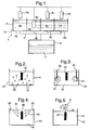
- Fig. 1 provides a schematic illustration of the arrangement described above with regard to the present invention.
- the arrangement 1 comprises a tank combination 2 in which a number of dip tanks 3 are arranged to receive an equal volume of leaching fluid or solution 4 in order that cores 5 comprising a soluble part and an unsoluble part can be dipped and immersed in the leaching fluid 4.
- a rail may be provided in order to present the cores 5 to the fluid 4 appropriately.
- one core 5 may be presented at a time to a respective dip tank 3 and therefore its leaching fluid 4 or a group of cores presented at the same time.
- the objective is to provide consistency between leaching operations and one particular way of achieving that is the utilisation of the leaching fluid in one tank 3 until saturated or aged, and then whilst that tank and its leaching fluid 4 is re-generated, another tank 3 and its leaching fluid 4 is then utilised for leach erosion of the soluble part of the core in order to create the component structure required.
- Fig. 1 The particular adjustment depicted in Fig. 1, although others as described later will also be generally used, is to provide a pre-adjustment tank 6.
- This pre-adjustment tank 6 acts upon a bulk volume of leaching fluid 7 in order to homogenise the temperature and possibly other factors which may be variable across the leaching fluid, particularly if still. In such circumstances the pre-adjustment tank 6 effectively "calibrates" the leaching fluid to a known leaching efficiency which can then be utilised in determining other factors with respect to the necessity for erosion of the soluble part of the cores 5 in the actual leaching process stages.
- the pre-adjustment tank 6 will elevate the temperature of the fluid 7 to a value in the range 25 to 100°C with a bulk temperature accuracy of +/- 1°C.
- the adjusted leaching fluid 7 is pumped by an appropriate distribution arrangement 8 to the tanks, there is consistency with respect to the leaching efficiency of that fluid for greater confidence as to the erosion performance upon the core 5 and therefore predictability and consistency with respect to the core geometry eventually provided by removal of the soluble part of the initially moulded core prior to dipping in the leaching fluid.
- each dip tank 3 will incorporate a tap 9 (only shown with regard to dip tank 4a) and a drain 10 to allow rapid removal of saturated or exhausted leaching fluid 4a and replenishment with preadjusted leaching fluid 7 through the network 8 from the tank 6.
- a tap 9 only shown with regard to dip tank 4a
- a drain 10 to allow rapid removal of saturated or exhausted leaching fluid 4a and replenishment with preadjusted leaching fluid 7 through the network 8 from the tank 6.
- the removed exhausted or aged leaching fluid may be disposed of or more normally regenerated in some way in order to allow that leaching fluid to then be re-used in the leaching process.
- the used leaching fluid may be filtrated for blending to a leaching consistency.
- the system also allows the unleached parts to be set in discrete orientations to give easier manual regulation of batch leaching times and transferal into and out of the leaching arrangement and between separate leaching tanks. This allows preferential removal of soluble material from specific areas first and in the case of certain part geometries, their controlled orientation in the leaching tanks combined with thermal environmental manipulation can regulate and even corrected for internal stress and strain deformities produced during the moulding process. In this way the specific control of part orientation and temperature during leaching critically control the final components dimensional quality.
- the multi-tank system has the flexibility to allow the rapid start-up, emptying, and refill of any individual dip tank 3 during the leaching process to provide real-time and continuous leaching.
- Each dip tank 3 may have independent settings of leaching time, temperature, agitation and part orientation, different unleached part geometries can be incorporated in different tanks at the same time, and/or a successive multi-stage leaching for any particular part can be performed (i.e. similar to multi-stage scrubbing/polishing process.
- the present arrangement comprises provision of a tank combination in which at least one dip tank is associated with adjustment means to vary the effect and efficiency of the leaching solution for consistency across all cores of a number of cores to be processed or by selective variation in that leaching solution efficiency and effect and ability to determine the effects of varying leaching processes upon the component product produced.
- the adjustment as indicated is generally of a physical nature in terms of temperature, agitation of the leaching fluid, maintaining the operational leaching fluid within a calibrated efficiency spectrum and otherwise achieving operational consistency in terms of washing and drying of the cores after leaching. Approaches to achieving this adjustment in addition to providing the pre-adjustment tank for calibration of the leaching solution are described later with regard to Figs. 2 to 5.
- automation of the process is possible via a rail track or a carousel to facilitate the automated exposure of the unleached parts to the single/multi-stage tank leaching system with unleached parts placed or hung individually in stations with adjustable orientations and/or the use of part profile 'setters'.
- the timing of each parts exposure to the leaching solution could then be controlled either by the speed of the automated movement through the leaching process or via an alarmed timer associated with each dip tank.
- the use of alternative means to direct flow/agitation of the leaching fluid relative to the soluble part would also result in improvements to the rate of soluble material removal and the control of the leaching erosion process.
- the automated system described above may incorporate an additional rotational/translational manipulation of the unleached part during transit in the leaching tanks to regulate this flow and agitation relative to the leaching fluid.
- manipulation of the leaching fluid flow/agitation could be produced by directed water jets, physical or sonic oscillation of the tank or its components, or via more conventional means such as bubble curtains, paddles, stirrers and propellers.
- a system using enclosed and directed spray-jets could also be employed as an alternative to leaching solution submersion, this again would reduce system operating time and waste disposal.
- Fig. 2 depicting a cross-section of a first embodiment of a dip tank 13 in accordance with the present invention
- a core 15 is immersed in a leaching solution 14.
- this leaching solution 14 will generally have been "calibrated" in a pre-adjustment tank in terms of temperature and other factors for consistency with other dip tanks (not shown) in a tank combination or at least adjusted for consistency between leaching solutions utilised with respect to each core 15 presented in a number of cores in a batch.
- Fig. 2 depicting a cross-section of a first embodiment of a dip tank 13 in accordance with the present invention
- the leaching solution 14 is agitated in order to homogenise the leaching solution 15 throughout the bulk within the tank 13.
- bubbles 16 are generated by an appropriate mechanism in order to create agitation within the leaching fluid 14. These bubbles stir the fluid 14 about and into the core 15. In such circumstances, the fluid 14 is not stagnant and the leaching effect therefore promoted. It will be understood that for consistency the bubbles 16 are generated either uniformly for each core 15 presented or agitation through the bubbles may be increased or decreased dependent upon the saturation age of the leaching solution 14 or its temperature or other physical factors in order to equalise the leaching effect across all cores 15 of a number of cores in a batch.
- Fig. 3 illustrates a second embodiment of a dip tank 23 in accordance with the present invention.
- the dip tank 23 again incorporates a body of leaching fluid 24.
- the leaching fluid or solution 24 as indicated previously will be substantially homogenised by a pre adjustment process in terms of temperature and other leaching effects for consistency across all cores 25 to be processed in a batch.
- ultra sonic wands 20 are arranged to create sonic booms 21 which agitate the fluid or solution 24.
- These sonic booms 21 create fluid flow within the leaching fluid or solution 24, again facilitating the leaching process with regard to the core 25.
- the degree of agitation created by the booms 21 can be rendered consistent for all cores 25 presented or adjusted to take account of varying physical factors with respect to the leaching solution 24 for consistency of leaching effect across all the cores 25 of a batch.
- Fig. 4 illustrates a third embodiment of a dip tank 33 in accordance with the present invention.
- a volume of leaching solution is sprayed by spray heads 30 towards a core 35.
- a spray suspension 34 is projected towards the core 35 such that there is a volume of leaching mist solution about the core 35.
- Such a leaching mist creates an even exposure of the core 35 to the leaching solution effectively in suspension about the core 35.
- the leaching solution may be pumped directly from the homogenising and calibrating pre-adjustment tank for the bulk of the leaching fluid as described previously.
- leaching solution will drip from the core 35 towards a base 31 of the dip tank 33.
- the collected used leaching solution will then either be regenerated for re-use via adjustment in the pre-adjustment tank as described previously in order to achieve a calibrated leaching efficiency or may be disposed of.
- Fig. 5 illustrates a fourth embodiment of a dip tank 43 in accordance with the present invention.
- the dip tank 43 incorporates the volume of leaching solution 44 with a core 45 immersed in that solution 44.
- the core 45 is mounted upon a hanger 46 which as described previously will automatically dip the core 45 in the solution 44 in order to leach the soluble part of the core 45 and so create a component as required.
- the core is manipulated in a swish fashion. This manipulation generates fluid flow about the core 45 in order to facilitate leaching.
- the swishing motion may be a simple lateral side to side motion depicted by arrowheads A or a twisting motion depicted by arrowheads B or most preferably a combination.
Landscapes
- Engineering & Computer Science (AREA)
- Mechanical Engineering (AREA)
- Manufacture And Refinement Of Metals (AREA)
- Molds, Cores, And Manufacturing Methods Thereof (AREA)
- Casting Devices For Molds (AREA)
Applications Claiming Priority (1)
| Application Number | Priority Date | Filing Date | Title |
|---|---|---|---|
| GBGB0506834.1A GB0506834D0 (en) | 2005-04-05 | 2005-04-05 | Core leaching |
Publications (3)
| Publication Number | Publication Date |
|---|---|
| EP1710029A2 true EP1710029A2 (fr) | 2006-10-11 |
| EP1710029A3 EP1710029A3 (fr) | 2006-10-18 |
| EP1710029B1 EP1710029B1 (fr) | 2011-12-21 |
Family
ID=34586683
Family Applications (1)
| Application Number | Title | Priority Date | Filing Date |
|---|---|---|---|
| EP06251175A Ceased EP1710029B1 (fr) | 2005-04-05 | 2006-03-04 | Dissoultion pour noyau |
Country Status (3)
| Country | Link |
|---|---|
| US (1) | US7935295B2 (fr) |
| EP (1) | EP1710029B1 (fr) |
| GB (1) | GB0506834D0 (fr) |
Cited By (4)
| Publication number | Priority date | Publication date | Assignee | Title |
|---|---|---|---|---|
| RU2398654C1 (ru) * | 2009-05-20 | 2010-09-10 | Владислав Петрович Алёшин | Установка выщелачивания барабанного типа ультразвуковая |
| RU2414326C1 (ru) * | 2009-10-15 | 2011-03-20 | Владислав Петрович Алёшин | Способ и устройство удаления керамического материала из отливок |
| FR3036637A1 (fr) * | 2015-05-29 | 2016-12-02 | Snecma | Procede de decochage d'un noyau de fonderie, et procede de fabrication par moulage comportant un tel procede |
| CN107855503A (zh) * | 2017-10-31 | 2018-03-30 | 西安交通大学 | 一种通过气流搅拌提高氧化铝基陶瓷型芯脱除速率的脱芯设备 |
Families Citing this family (2)
| Publication number | Priority date | Publication date | Assignee | Title |
|---|---|---|---|---|
| CN108746567B (zh) * | 2018-07-19 | 2024-09-13 | 山东联诚精密制造股份有限公司 | 一种铝铸造水除砂芯系统 |
| RU2761399C1 (ru) * | 2021-04-16 | 2021-12-08 | Анатолий Николаевич Воронцов | Установка для выщелачивания керамики из металлургических отливок (варианты) |
Citations (1)
| Publication number | Priority date | Publication date | Assignee | Title |
|---|---|---|---|---|
| GB806479A (en) | 1956-09-12 | 1958-12-23 | Wiggin & Co Ltd Henry | Improvements relating to the production of metal articles with holes in them |
Family Cites Families (13)
| Publication number | Priority date | Publication date | Assignee | Title |
|---|---|---|---|---|
| GB404972A (en) * | 1932-05-26 | 1934-01-26 | Sherard Osborn Cowper Coles | Improvements in the electrolytic coating of metals with other metals |
| BE556813A (fr) * | 1956-04-28 | |||
| US3661660A (en) * | 1968-02-21 | 1972-05-09 | Grace W R & Co | Method for ultrasonic etching of polymeric printing plates |
| GB1260271A (en) * | 1969-06-30 | 1972-01-12 | Buckbee Mears Co | Method and apparatus for electrolytic plating |
| US4162173A (en) | 1977-03-09 | 1979-07-24 | General Electric Company | Molten salt leach for removal of inorganic cores from directionally solidified eutectic alloy structures |
| US5080839A (en) * | 1990-04-17 | 1992-01-14 | Johnson & Johnson Vision Products, Inc. | Process for hydrating soft contact lenses |
| US5262100A (en) | 1990-07-11 | 1993-11-16 | Advanced Plastics Partnership | Method of core removal from molded products |
| US5401379A (en) * | 1993-03-19 | 1995-03-28 | Mazzochi; James L. | Chrome plating process |
| AU6327398A (en) * | 1997-02-18 | 1998-09-08 | Scp Global Technologies | Multiple stage wet processing chamber |
| US6354310B1 (en) * | 1998-11-12 | 2002-03-12 | General Electric Company | Apparatus and process to clean and strip coatings from hardware |
| KR100685918B1 (ko) * | 2000-12-27 | 2007-02-22 | 엘지.필립스 엘시디 주식회사 | 유리기판 식각장치 및 이를 이용한 유리기판 식각방법 |
| DE10141633A1 (de) | 2001-08-24 | 2003-03-13 | Eichenauer Gmbh & Co Kg F | Verfahren und Vorrichtung zum Entkernen wasserlöslicher Gießkerne |
| DE60322367D1 (de) | 2002-04-11 | 2008-09-04 | Rolls Royce Corp | Verfahren und vorrichtung zum entfernen von keramikmaterial von gusskomponenten |
-
2005
- 2005-04-05 GB GBGB0506834.1A patent/GB0506834D0/en not_active Ceased
-
2006
- 2006-03-04 EP EP06251175A patent/EP1710029B1/fr not_active Ceased
- 2006-03-06 US US11/367,505 patent/US7935295B2/en not_active Expired - Fee Related
Patent Citations (1)
| Publication number | Priority date | Publication date | Assignee | Title |
|---|---|---|---|---|
| GB806479A (en) | 1956-09-12 | 1958-12-23 | Wiggin & Co Ltd Henry | Improvements relating to the production of metal articles with holes in them |
Cited By (8)
| Publication number | Priority date | Publication date | Assignee | Title |
|---|---|---|---|---|
| RU2398654C1 (ru) * | 2009-05-20 | 2010-09-10 | Владислав Петрович Алёшин | Установка выщелачивания барабанного типа ультразвуковая |
| RU2456122C2 (ru) * | 2009-05-20 | 2012-07-20 | Федеральное государственное унитарное предприятие "Научно-производственный центр газотурбостроения "Салют" | Установка выщелачивания барабанного типа ультразвуковая |
| RU2414326C1 (ru) * | 2009-10-15 | 2011-03-20 | Владислав Петрович Алёшин | Способ и устройство удаления керамического материала из отливок |
| RU2456123C2 (ru) * | 2009-10-15 | 2012-07-20 | Федеральное государственное унитарное предприятие "Научно-производственный центр газотурбостроения "Салют" | Способ и устройство удаления керамического материала из отливок |
| FR3036637A1 (fr) * | 2015-05-29 | 2016-12-02 | Snecma | Procede de decochage d'un noyau de fonderie, et procede de fabrication par moulage comportant un tel procede |
| WO2016193567A1 (fr) * | 2015-05-29 | 2016-12-08 | Safran Aircraft Engines | Procede de decochage d'un noyau de fonderie, et procede de fabrication par moulage comportant un tel procede |
| US10870147B2 (en) | 2015-05-29 | 2020-12-22 | Snecma | Method for knocking out a foundry core and method for manufacturing by casting comprising such a method |
| CN107855503A (zh) * | 2017-10-31 | 2018-03-30 | 西安交通大学 | 一种通过气流搅拌提高氧化铝基陶瓷型芯脱除速率的脱芯设备 |
Also Published As
| Publication number | Publication date |
|---|---|
| GB0506834D0 (en) | 2005-05-11 |
| US7935295B2 (en) | 2011-05-03 |
| EP1710029B1 (fr) | 2011-12-21 |
| EP1710029A3 (fr) | 2006-10-18 |
| US20060219664A1 (en) | 2006-10-05 |
Similar Documents
| Publication | Publication Date | Title |
|---|---|---|
| US10016945B2 (en) | Support structure removal system | |
| EP3060380B1 (fr) | Procédé et appareil de fabrication additive | |
| US7935295B2 (en) | Core leaching | |
| US20160074911A1 (en) | Washing apparatus for removing support material from 3d-printed articles | |
| JP2021505433A (ja) | 表面仕上げおよび支持材料除去のための方法および装置(deci duo) | |
| US6355104B1 (en) | Article treating apparatus and method and control system therefor | |
| JP2017521258A (ja) | 航空機タービンエンジンの羽根付き要素をロストワックス鋳造で作成するためのシェル鋳型の改良された製造方法 | |
| WO2019115101A1 (fr) | Système et procédé permettant de remplir un récipient avec un fluide et/ou de faire fonctionner un système de mélange | |
| DE4326982C1 (de) | Verfahren und Vorrichtung zur Herstellung von Formteilen aus Metallschaum | |
| US3849197A (en) | Method and apparatus for decontaminating a rinse liquid | |
| WO2019203852A1 (fr) | Compositions destinées à éliminer la résine d'un objet imprimé en 3d et procédés de fabrication et d'utilisation de ces dernières | |
| US7703463B2 (en) | Method of pickling a hollow part in the form of a body of revolution, and apparatus implementing such a method | |
| WO2019166166A1 (fr) | Retrait des structures de support de composants fabriqués par impression 3d | |
| KR101079146B1 (ko) | 시편 현출용 부식 장치 및 방법 | |
| US3348605A (en) | Method and apparatus for forming cast objects using expendable patterns | |
| JP2005206928A (ja) | チタン又はチタン合金の電解研磨方法とその装置 | |
| JP2002210399A (ja) | 塗料液撹拌方法及びその装置 | |
| JP4729294B2 (ja) | 車体パネル周辺の流体解析方法及び車体パネル周辺の流体解析プログラム | |
| KR20210036050A (ko) | 크리스탈 모니터 센서 제조용 자동 에칭 장치 | |
| CN206383510U (zh) | 湿法3d打印机 | |
| JPH1157945A (ja) | どぶ漬装置 | |
| JP5339235B2 (ja) | 小部品の無電解メッキ方法及び無電解メッキ装置 | |
| EP1493065B1 (fr) | Dispositif et procede pour simuler des processus de production | |
| US2376281A (en) | Method and apparatus for producing latex foam | |
| JPS58123730A (ja) | 半導体ウエハ−エツチング装置 |
Legal Events
| Date | Code | Title | Description |
|---|---|---|---|
| PUAI | Public reference made under article 153(3) epc to a published international application that has entered the european phase |
Free format text: ORIGINAL CODE: 0009012 |
|
| PUAL | Search report despatched |
Free format text: ORIGINAL CODE: 0009013 |
|
| AK | Designated contracting states |
Kind code of ref document: A2 Designated state(s): AT BE BG CH CY CZ DE DK EE ES FI FR GB GR HU IE IS IT LI LT LU LV MC NL PL PT RO SE SI SK TR |
|
| AX | Request for extension of the european patent |
Extension state: AL BA HR MK YU |
|
| AK | Designated contracting states |
Kind code of ref document: A3 Designated state(s): AT BE BG CH CY CZ DE DK EE ES FI FR GB GR HU IE IS IT LI LT LU LV MC NL PL PT RO SE SI SK TR |
|
| AX | Request for extension of the european patent |
Extension state: AL BA HR MK YU |
|
| 17P | Request for examination filed |
Effective date: 20061009 |
|
| 17Q | First examination report despatched |
Effective date: 20070416 |
|
| AKX | Designation fees paid |
Designated state(s): DE FR GB |
|
| GRAP | Despatch of communication of intention to grant a patent |
Free format text: ORIGINAL CODE: EPIDOSNIGR1 |
|
| GRAS | Grant fee paid |
Free format text: ORIGINAL CODE: EPIDOSNIGR3 |
|
| GRAA | (expected) grant |
Free format text: ORIGINAL CODE: 0009210 |
|
| AK | Designated contracting states |
Kind code of ref document: B1 Designated state(s): DE FR GB |
|
| REG | Reference to a national code |
Ref country code: GB Ref legal event code: FG4D |
|
| REG | Reference to a national code |
Ref country code: DE Ref legal event code: R096 Ref document number: 602006026483 Country of ref document: DE Effective date: 20120308 |
|
| PLBE | No opposition filed within time limit |
Free format text: ORIGINAL CODE: 0009261 |
|
| STAA | Information on the status of an ep patent application or granted ep patent |
Free format text: STATUS: NO OPPOSITION FILED WITHIN TIME LIMIT |
|
| 26N | No opposition filed |
Effective date: 20120924 |
|
| REG | Reference to a national code |
Ref country code: DE Ref legal event code: R097 Ref document number: 602006026483 Country of ref document: DE Effective date: 20120924 |
|
| REG | Reference to a national code |
Ref country code: FR Ref legal event code: PLFP Year of fee payment: 10 |
|
| REG | Reference to a national code |
Ref country code: FR Ref legal event code: PLFP Year of fee payment: 11 |
|
| REG | Reference to a national code |
Ref country code: FR Ref legal event code: PLFP Year of fee payment: 12 |
|
| REG | Reference to a national code |
Ref country code: FR Ref legal event code: PLFP Year of fee payment: 13 |
|
| PGFP | Annual fee paid to national office [announced via postgrant information from national office to epo] |
Ref country code: FR Payment date: 20210326 Year of fee payment: 16 |
|
| PGFP | Annual fee paid to national office [announced via postgrant information from national office to epo] |
Ref country code: GB Payment date: 20210326 Year of fee payment: 16 |
|
| PGFP | Annual fee paid to national office [announced via postgrant information from national office to epo] |
Ref country code: DE Payment date: 20210527 Year of fee payment: 16 |
|
| REG | Reference to a national code |
Ref country code: DE Ref legal event code: R119 Ref document number: 602006026483 Country of ref document: DE |
|
| GBPC | Gb: european patent ceased through non-payment of renewal fee |
Effective date: 20220304 |
|
| PG25 | Lapsed in a contracting state [announced via postgrant information from national office to epo] |
Ref country code: GB Free format text: LAPSE BECAUSE OF NON-PAYMENT OF DUE FEES Effective date: 20220304 Ref country code: FR Free format text: LAPSE BECAUSE OF NON-PAYMENT OF DUE FEES Effective date: 20220331 Ref country code: DE Free format text: LAPSE BECAUSE OF NON-PAYMENT OF DUE FEES Effective date: 20221001 |