EP1710083A1 - Plaque à diaphragme avec sortie partiellement gravée - Google Patents
Plaque à diaphragme avec sortie partiellement gravée Download PDFInfo
- Publication number
- EP1710083A1 EP1710083A1 EP06112310A EP06112310A EP1710083A1 EP 1710083 A1 EP1710083 A1 EP 1710083A1 EP 06112310 A EP06112310 A EP 06112310A EP 06112310 A EP06112310 A EP 06112310A EP 1710083 A1 EP1710083 A1 EP 1710083A1
- Authority
- EP
- European Patent Office
- Prior art keywords
- etched
- partially
- port
- diaphragm plate
- predetermined region
- Prior art date
- Legal status (The legal status is an assumption and is not a legal conclusion. Google has not performed a legal analysis and makes no representation as to the accuracy of the status listed.)
- Granted
Links
- 238000005530 etching Methods 0.000 claims description 16
- 238000000034 method Methods 0.000 claims description 12
- 230000002093 peripheral effect Effects 0.000 claims description 5
- 239000012530 fluid Substances 0.000 claims 3
- 230000000994 depressogenic effect Effects 0.000 abstract description 4
- 238000010586 diagram Methods 0.000 description 13
- 239000000463 material Substances 0.000 description 5
- 238000004519 manufacturing process Methods 0.000 description 2
- 239000002184 metal Substances 0.000 description 2
- 238000005452 bending Methods 0.000 description 1
- 238000004891 communication Methods 0.000 description 1
- 238000005516 engineering process Methods 0.000 description 1
- 238000010348 incorporation Methods 0.000 description 1
- 230000003278 mimic effect Effects 0.000 description 1
- 238000000926 separation method Methods 0.000 description 1
Images


Classifications
-
- B—PERFORMING OPERATIONS; TRANSPORTING
- B41—PRINTING; LINING MACHINES; TYPEWRITERS; STAMPS
- B41J—TYPEWRITERS; SELECTIVE PRINTING MECHANISMS, i.e. MECHANISMS PRINTING OTHERWISE THAN FROM A FORME; CORRECTION OF TYPOGRAPHICAL ERRORS
- B41J2/00—Typewriters or selective printing mechanisms characterised by the printing or marking process for which they are designed
- B41J2/005—Typewriters or selective printing mechanisms characterised by the printing or marking process for which they are designed characterised by bringing liquid or particles selectively into contact with a printing material
- B41J2/01—Ink jet
- B41J2/135—Nozzles
- B41J2/16—Production of nozzles
- B41J2/1621—Manufacturing processes
- B41J2/1626—Manufacturing processes etching
-
- B—PERFORMING OPERATIONS; TRANSPORTING
- B41—PRINTING; LINING MACHINES; TYPEWRITERS; STAMPS
- B41J—TYPEWRITERS; SELECTIVE PRINTING MECHANISMS, i.e. MECHANISMS PRINTING OTHERWISE THAN FROM A FORME; CORRECTION OF TYPOGRAPHICAL ERRORS
- B41J2/00—Typewriters or selective printing mechanisms characterised by the printing or marking process for which they are designed
- B41J2/005—Typewriters or selective printing mechanisms characterised by the printing or marking process for which they are designed characterised by bringing liquid or particles selectively into contact with a printing material
- B41J2/01—Ink jet
-
- B—PERFORMING OPERATIONS; TRANSPORTING
- B41—PRINTING; LINING MACHINES; TYPEWRITERS; STAMPS
- B41J—TYPEWRITERS; SELECTIVE PRINTING MECHANISMS, i.e. MECHANISMS PRINTING OTHERWISE THAN FROM A FORME; CORRECTION OF TYPOGRAPHICAL ERRORS
- B41J2/00—Typewriters or selective printing mechanisms characterised by the printing or marking process for which they are designed
- B41J2/005—Typewriters or selective printing mechanisms characterised by the printing or marking process for which they are designed characterised by bringing liquid or particles selectively into contact with a printing material
- B41J2/01—Ink jet
- B41J2/015—Ink jet characterised by the jet generation process
- B41J2/04—Ink jet characterised by the jet generation process generating single droplets or particles on demand
- B41J2/045—Ink jet characterised by the jet generation process generating single droplets or particles on demand by pressure, e.g. electromechanical transducers
-
- B—PERFORMING OPERATIONS; TRANSPORTING
- B41—PRINTING; LINING MACHINES; TYPEWRITERS; STAMPS
- B41J—TYPEWRITERS; SELECTIVE PRINTING MECHANISMS, i.e. MECHANISMS PRINTING OTHERWISE THAN FROM A FORME; CORRECTION OF TYPOGRAPHICAL ERRORS
- B41J2/00—Typewriters or selective printing mechanisms characterised by the printing or marking process for which they are designed
- B41J2/005—Typewriters or selective printing mechanisms characterised by the printing or marking process for which they are designed characterised by bringing liquid or particles selectively into contact with a printing material
- B41J2/01—Ink jet
- B41J2/015—Ink jet characterised by the jet generation process
- B41J2/04—Ink jet characterised by the jet generation process generating single droplets or particles on demand
- B41J2/045—Ink jet characterised by the jet generation process generating single droplets or particles on demand by pressure, e.g. electromechanical transducers
- B41J2/05—Ink jet characterised by the jet generation process generating single droplets or particles on demand by pressure, e.g. electromechanical transducers produced by the application of heat
-
- B—PERFORMING OPERATIONS; TRANSPORTING
- B41—PRINTING; LINING MACHINES; TYPEWRITERS; STAMPS
- B41J—TYPEWRITERS; SELECTIVE PRINTING MECHANISMS, i.e. MECHANISMS PRINTING OTHERWISE THAN FROM A FORME; CORRECTION OF TYPOGRAPHICAL ERRORS
- B41J2/00—Typewriters or selective printing mechanisms characterised by the printing or marking process for which they are designed
- B41J2/005—Typewriters or selective printing mechanisms characterised by the printing or marking process for which they are designed characterised by bringing liquid or particles selectively into contact with a printing material
- B41J2/01—Ink jet
- B41J2/135—Nozzles
- B41J2/14—Structure thereof only for on-demand ink jet heads
-
- B—PERFORMING OPERATIONS; TRANSPORTING
- B41—PRINTING; LINING MACHINES; TYPEWRITERS; STAMPS
- B41J—TYPEWRITERS; SELECTIVE PRINTING MECHANISMS, i.e. MECHANISMS PRINTING OTHERWISE THAN FROM A FORME; CORRECTION OF TYPOGRAPHICAL ERRORS
- B41J2/00—Typewriters or selective printing mechanisms characterised by the printing or marking process for which they are designed
- B41J2/005—Typewriters or selective printing mechanisms characterised by the printing or marking process for which they are designed characterised by bringing liquid or particles selectively into contact with a printing material
- B41J2/01—Ink jet
- B41J2/135—Nozzles
- B41J2/16—Production of nozzles
Definitions
- Drop on demand inkjet technology for producing printed media has been employed in commercial products such as printers, plotters, and facsimile machines.
- an ink jet image is formed by selective placement on a receiver surface of ink drops emitted by a plurality of drop generators implemented, for example, in a printhead comprising a stack of metal plates having fluidic chambers and channels formed therein (commonly referred to as a jet stack assembly).
- Ink is stored in an ink reservoir and loaded into the printhead assembly through ports in a diaphragm plate on the back side of the printhead assembly.
- ports are formed in the diaphragm prior to incorporation of the diaphragm into the jet stack assembly. Ports typically are formed by etching through the diaphragm.
- the perimeter region is fractured at the partially etched perimeter portion and bent at the non-etched perimeter portion.
- the non-etched perimeter portion is structured to prevent separation of the diaphragm plate and a leaflet defined by the partial-etched portion.
- the diaphragm plate is attached to the body. In one embodiment of the printhead of claim 7, it further comprises:
- FIG. 1 is a cross-sectional side view diagram of a jet stack assembly for a printhead.
- FIG. 2 is a plan view diagram of the jet stack assembly of FIG. 1.
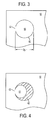
- FIG. 3 is a plan view diagram of a first embodiment of a partially-etched port.
- FIG. 4 is a plan view diagram of the first embodiment partially-etched port after piercing.
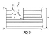
- FIG. 5 is a cross-sectional side view diagram of the partially-etched port of FIG. 4 after piercing.
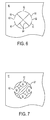
- FIG. 6 is a plan view diagram of a second embodiment of a partially-etched port.
- FIG. 7 is a plan view diagram of the second embodiment partially-etched port after piercing.
- FIG. 8 is a cross-sectional side view diagram of the partially-etched port of FIG. 7 after piercing.
- FIGS. 1 and 2 are cross-sectional side and plan view diagrams, respectively, of a printhead assembly 1 for a printhead.
- the printhead assembly 1 includes a diaphragm plate 10, aperture plate 20, and body 30 intermediate the aperture plate 20 and diaphragm plate 10.
- the body 30 can include a jet stack comprising one or more metal plates (not shown) with openings therein that form fluidic channels and fluidic chambers when the plates are assembled into a body.
- the printhead assembly 1 has a thickness T S , which can be generally on the order of 90 mils.
- a diaphragm plate (or diaphragm) 10 of a printhead assembly 1 generally includes ports 40 permitting communication of a reservoir (not shown) and chambers 42 within the printhead assembly 1.
- Ports 40 can be curved in shape, with an exemplary circular port having a diameter D P of less than 10 mils but not greater 250 mils.
- FIG. 3 is a plan view diagram of a first embodiment partially-etched port trace 50 formed on a diaphragm 10 of a printhead assembly 1.
- this embodiment includes a curved port perimeter or port boundary having a partially-etched arc 60 comprising a substantial portion thereof partially-etched into the diaphragm plate 10 material.
- a non-etched hinge region 62 remains at the remaining portion of the curved port boundary.
- the partially-etched arc 60 comprises about 90% of the port boundary, although a greater or lesser percentage may be efficaciously employed.
- FIGS. 4 and 5 are plan and cross-sectional side view diagrams showing the port 40 of FIG. 3 after piercing.
- the diaphragm plate 10 fractures along the partially-etched arc 60.
- a port 40 is opened thereby and a leaflet 52 is formed by the depressed or pierced portion of the diaphragm plate 10.
- the leaflet 52 generally is disposed at an angle to the diaphragm plate 10 after depression. It is readily appreciated that the leaflet 52 can be deflected out of the plane of the diaphragm plate 10, while the non-etched hinge region 62 retains the leaflet 52 and thereby prevents it from breaking off.
- the material used to make the diaphragm plate 10 may permit the leaflet 52 to rebound slightly after depression.
- the hinge region 62 can be configured to provide maximum deflection of the leaflet 52 without fracture of the hinge region 62 for a given diaphragm plate 10 material.
- FIG. 6 is a plan view diagram of a second embodiment of a partially-etched port trace formed on a diaphragm plate 10.
- the partial-etching in this embodiment includes a curved port boundary having four port boundary partial-etches 60 partially etched thereon into the diaphragm plate 10 material.
- Corresponding four non-etched port boundary hinges 62 remain at the curved port boundary or port perimeter.
- Two generally linear partial-etches 64 are further partially-etched, each generally linear partial-etch in this embodiment extending across the port boundary and connecting two port boundary partial-etches.
- An individual leaflet 52 can be pie-, V- or wedge-shaped, and either of the leaflet 52 or the port trace can be considered a partially-etched predetermined portion.
- FIGS. 7 and 8 are plan and cross-sectional side view diagrams of the open port 40 of FIG. 6 after piercing or depression.
- the diaphragm plate 10 material fractured along the port boundary partial-etches 60 and generally linear partial-etch 64.
- the port 40 was opened thereby and leaflets 52 were formed by the depressed or pierced portions of the diaphragm plate 10.
- the depressed leaflets 52 reside out of the plane of the diaphragm plate 10.
- the leaflets 52 may be deflected into the body and toward the chamber 42.
- the number of port boundary partial-etches 60 in the second embodiment need not be limited to four. In other embodiments, partially-etched arcs and an alternating non-etched arcs can be disposed on the diaphragm plate 10. Generally linear partial-etches 64 would be partially-etched, each generally linear partial-etch 64 disposed within the port area 50 and connecting to at least one partially-etched arc 60 on the port boundary.
- an embodiment (not shown) similar to the embodiment of FIG. 6 may be formed having three partially-etched arcs and three radial and generally linear partial-etches, with each generally linear partial-etch extending generally from the central region of the port boundary to a partially-etched arc. It should be understood that a variety of partially-etched arc/generally linear partial-etch configurations may be employed to generate various multi-leaflet structures, and that such variations and multi-leaflet structures are within the scope of the present disclosure.
- partial etching is performed on the reverse or second side of the diaphragm 10. This partial etching may but is not required to mimic the etching of the first side of the diaphragm 10.
- the non-partially-etched hinge region 62 may be partially etched on a reverse side of the diaphragm 10 to facilitate hinging or to promote hinging in a specific locus or pattern.
- An advantage of the present port trace 50 is that the port traces 50 are shaped in the partial-etching step and pierced to form an open port 40.
- the present method therefore permits utilization of elliptical, crenate or other port boundary shapes as desired.
- the partially-etched arcs be of equal length; partial-etches of different lengths may be employed, resulting in non-equal leaflets.
- the generally linear partial-etch of FIGS. 6-8 need not be generally linear, but may instead be partially-etched in an arcuate or curvilinear configuration. Such leaflet variations may be used to affect flow characteristics of ink through the open port and into the fluidic chamber.
Landscapes
- Engineering & Computer Science (AREA)
- Manufacturing & Machinery (AREA)
- Particle Formation And Scattering Control In Inkjet Printers (AREA)
Applications Claiming Priority (1)
| Application Number | Priority Date | Filing Date | Title |
|---|---|---|---|
| US11/101,763 US7549733B2 (en) | 2005-04-07 | 2005-04-07 | Diaphragm plate with partially-etched port |
Publications (2)
| Publication Number | Publication Date |
|---|---|
| EP1710083A1 true EP1710083A1 (fr) | 2006-10-11 |
| EP1710083B1 EP1710083B1 (fr) | 2012-03-21 |
Family
ID=36618836
Family Applications (1)
| Application Number | Title | Priority Date | Filing Date |
|---|---|---|---|
| EP06112310A Expired - Lifetime EP1710083B1 (fr) | 2005-04-07 | 2006-04-06 | Plaque à diaphragme avec sortie partiellement gravée |
Country Status (5)
| Country | Link |
|---|---|
| US (2) | US7549733B2 (fr) |
| EP (1) | EP1710083B1 (fr) |
| JP (1) | JP2006289978A (fr) |
| KR (1) | KR101304953B1 (fr) |
| CN (1) | CN1843761B (fr) |
Citations (6)
| Publication number | Priority date | Publication date | Assignee | Title |
|---|---|---|---|---|
| EP0564295A1 (fr) * | 1992-04-02 | 1993-10-06 | Hewlett-Packard Company | Tête d'impression et son procédé de fabrication |
| US5551618A (en) * | 1992-06-30 | 1996-09-03 | Fuji Xerox Co., Ltd. | Apparatus for cutting plate-shaped brittle material |
| JPH10305605A (ja) * | 1997-05-08 | 1998-11-17 | Toshiba Electron Eng Corp | グレーズド基板、サーマルプリントヘッドおよびサーマルプリントヘッドの製造方法 |
| EP0903234A2 (fr) * | 1997-09-17 | 1999-03-24 | Seiko Epson Corporation | Micro-dispositif |
| US6142611A (en) * | 1992-10-23 | 2000-11-07 | Pan; Alfred I-Tsung | Oxide island structure for flexible inkjet printhead and method of manufacture thereof |
| US20030063137A1 (en) * | 2001-09-13 | 2003-04-03 | Seiko Epson Corporation | Liquid jetting head, method of manufacturing the same, and liquid jetting apparatus incorporating the same |
Family Cites Families (5)
| Publication number | Priority date | Publication date | Assignee | Title |
|---|---|---|---|---|
| US5828394A (en) * | 1995-09-20 | 1998-10-27 | The Board Of Trustees Of The Leland Stanford Junior University | Fluid drop ejector and method |
| JPH11192701A (ja) * | 1997-09-17 | 1999-07-21 | Seiko Epson Corp | マイクロデバイス、インクジェット式記録ヘッド及びこれらの製造方法並びにインクジェット式記録装置 |
| US6302529B1 (en) * | 1998-04-16 | 2001-10-16 | Victor Company Of Japan, Ltd. | Electrostatic ink-jet printer |
| US6302526B1 (en) * | 2000-02-03 | 2001-10-16 | Wisertek International Corp. | Electrode type print head for printing apparatus and method of manufacturing the same |
| US6540339B2 (en) * | 2001-03-21 | 2003-04-01 | Hewlett-Packard Company | Flextensional transducer assembly including array of flextensional transducers |
-
2005
- 2005-04-07 US US11/101,763 patent/US7549733B2/en not_active Expired - Fee Related
-
2006
- 2006-04-04 JP JP2006102789A patent/JP2006289978A/ja active Pending
- 2006-04-06 CN CN2006100732503A patent/CN1843761B/zh not_active Expired - Fee Related
- 2006-04-06 KR KR1020060031258A patent/KR101304953B1/ko not_active Expired - Fee Related
- 2006-04-06 EP EP06112310A patent/EP1710083B1/fr not_active Expired - Lifetime
-
2009
- 2009-05-15 US US12/467,162 patent/US7946689B2/en not_active Expired - Fee Related
Patent Citations (6)
| Publication number | Priority date | Publication date | Assignee | Title |
|---|---|---|---|---|
| EP0564295A1 (fr) * | 1992-04-02 | 1993-10-06 | Hewlett-Packard Company | Tête d'impression et son procédé de fabrication |
| US5551618A (en) * | 1992-06-30 | 1996-09-03 | Fuji Xerox Co., Ltd. | Apparatus for cutting plate-shaped brittle material |
| US6142611A (en) * | 1992-10-23 | 2000-11-07 | Pan; Alfred I-Tsung | Oxide island structure for flexible inkjet printhead and method of manufacture thereof |
| JPH10305605A (ja) * | 1997-05-08 | 1998-11-17 | Toshiba Electron Eng Corp | グレーズド基板、サーマルプリントヘッドおよびサーマルプリントヘッドの製造方法 |
| EP0903234A2 (fr) * | 1997-09-17 | 1999-03-24 | Seiko Epson Corporation | Micro-dispositif |
| US20030063137A1 (en) * | 2001-09-13 | 2003-04-03 | Seiko Epson Corporation | Liquid jetting head, method of manufacturing the same, and liquid jetting apparatus incorporating the same |
Non-Patent Citations (1)
| Title |
|---|
| PATENT ABSTRACTS OF JAPAN vol. 1999, no. 02 26 February 1999 (1999-02-26) * |
Also Published As
| Publication number | Publication date |
|---|---|
| US20060227177A1 (en) | 2006-10-12 |
| US20090219349A1 (en) | 2009-09-03 |
| KR20060107362A (ko) | 2006-10-13 |
| KR101304953B1 (ko) | 2013-09-06 |
| US7549733B2 (en) | 2009-06-23 |
| CN1843761B (zh) | 2012-01-04 |
| EP1710083B1 (fr) | 2012-03-21 |
| JP2006289978A (ja) | 2006-10-26 |
| CN1843761A (zh) | 2006-10-11 |
| US7946689B2 (en) | 2011-05-24 |
Similar Documents
| Publication | Publication Date | Title |
|---|---|---|
| EP0519279B1 (fr) | Tête d'enregistrement du type à jet d'encre | |
| HK1000414B (en) | Recording head of an ink-jet type | |
| EP3199352B1 (fr) | Tête de déversement de liquide et dispositif d'impression l'utilisant | |
| EP2280826B1 (fr) | Plaque à cavités | |
| US6481834B2 (en) | Ink-jet recording head | |
| CN102639328A (zh) | 打印头单元 | |
| JPWO1998022288A1 (ja) | インクジェット式記録ヘッド | |
| EP1710083B1 (fr) | Plaque à diaphragme avec sortie partiellement gravée | |
| JP2005349687A (ja) | インクジェットヘッド | |
| EP1647404A3 (fr) | Imprimante et méthode de fabrication de l'unité de tête | |
| EP1329318B1 (fr) | Appareil d'éjection de fluide pouvant moduler le volume de goutte | |
| EP1733883B1 (fr) | Tête d'éjection de liquide et dispositif d'enregistrement | |
| JP4662027B2 (ja) | インクジェットヘッド及びその製造方法 | |
| JP2009233879A (ja) | 液体噴射ヘッド、液体噴射ヘッドの製造方法、及び、金属板の製造方法 | |
| JP2006068941A (ja) | 液滴噴射装置 | |
| JP2005059392A5 (fr) | ||
| JP2023044119A (ja) | 流路部材および液体吐出ヘッド | |
| EP1972449B1 (fr) | Appareil d'éjection de gouttelettes liquides | |
| EP3077204B1 (fr) | Plaque de restriction de fluide d'impression destinée à un ensemble tête d'impression à jet d'encre et procédé | |
| CN1878677B (zh) | 提高微滴定位精度的方法及其得到的喷墨打印头、打印盒和打印装置 | |
| JP4798252B2 (ja) | 液体噴射ヘッドの製造方法 | |
| JP2017144665A (ja) | インクジェットヘッドおよびインクジェット装置 | |
| JP2004306380A (ja) | 液体噴射ヘッドの製造方法 | |
| JPH10305584A (ja) | インクジェットプリンターヘッド用ノズル板の製造方法 | |
| JP4107345B2 (ja) | インクジェット記録ヘッド |
Legal Events
| Date | Code | Title | Description |
|---|---|---|---|
| PUAI | Public reference made under article 153(3) epc to a published international application that has entered the european phase |
Free format text: ORIGINAL CODE: 0009012 |
|
| AK | Designated contracting states |
Kind code of ref document: A1 Designated state(s): AT BE BG CH CY CZ DE DK EE ES FI FR GB GR HU IE IS IT LI LT LU LV MC NL PL PT RO SE SI SK TR |
|
| AX | Request for extension of the european patent |
Extension state: AL BA HR MK YU |
|
| 17P | Request for examination filed |
Effective date: 20070411 |
|
| AKX | Designation fees paid |
Designated state(s): DE FR GB |
|
| 17Q | First examination report despatched |
Effective date: 20070612 |
|
| GRAP | Despatch of communication of intention to grant a patent |
Free format text: ORIGINAL CODE: EPIDOSNIGR1 |
|
| GRAS | Grant fee paid |
Free format text: ORIGINAL CODE: EPIDOSNIGR3 |
|
| GRAA | (expected) grant |
Free format text: ORIGINAL CODE: 0009210 |
|
| AK | Designated contracting states |
Kind code of ref document: B1 Designated state(s): DE FR GB |
|
| REG | Reference to a national code |
Ref country code: GB Ref legal event code: FG4D |
|
| REG | Reference to a national code |
Ref country code: DE Ref legal event code: R096 Ref document number: 602006028281 Country of ref document: DE Effective date: 20120516 |
|
| PLBE | No opposition filed within time limit |
Free format text: ORIGINAL CODE: 0009261 |
|
| STAA | Information on the status of an ep patent application or granted ep patent |
Free format text: STATUS: NO OPPOSITION FILED WITHIN TIME LIMIT |
|
| 26N | No opposition filed |
Effective date: 20130102 |
|
| REG | Reference to a national code |
Ref country code: DE Ref legal event code: R097 Ref document number: 602006028281 Country of ref document: DE Effective date: 20130102 |
|
| PGFP | Annual fee paid to national office [announced via postgrant information from national office to epo] |
Ref country code: GB Payment date: 20140327 Year of fee payment: 9 |
|
| PGFP | Annual fee paid to national office [announced via postgrant information from national office to epo] |
Ref country code: DE Payment date: 20140321 Year of fee payment: 9 Ref country code: FR Payment date: 20140422 Year of fee payment: 9 |
|
| REG | Reference to a national code |
Ref country code: DE Ref legal event code: R119 Ref document number: 602006028281 Country of ref document: DE |
|
| GBPC | Gb: european patent ceased through non-payment of renewal fee |
Effective date: 20150406 |
|
| PG25 | Lapsed in a contracting state [announced via postgrant information from national office to epo] |
Ref country code: DE Free format text: LAPSE BECAUSE OF NON-PAYMENT OF DUE FEES Effective date: 20151103 Ref country code: GB Free format text: LAPSE BECAUSE OF NON-PAYMENT OF DUE FEES Effective date: 20150406 |
|
| REG | Reference to a national code |
Ref country code: FR Ref legal event code: ST Effective date: 20151231 |
|
| PG25 | Lapsed in a contracting state [announced via postgrant information from national office to epo] |
Ref country code: FR Free format text: LAPSE BECAUSE OF NON-PAYMENT OF DUE FEES Effective date: 20150430 |