EP0564295A1 - Tête d'impression et son procédé de fabrication - Google Patents
Tête d'impression et son procédé de fabrication Download PDFInfo
- Publication number
- EP0564295A1 EP0564295A1 EP93302603A EP93302603A EP0564295A1 EP 0564295 A1 EP0564295 A1 EP 0564295A1 EP 93302603 A EP93302603 A EP 93302603A EP 93302603 A EP93302603 A EP 93302603A EP 0564295 A1 EP0564295 A1 EP 0564295A1
- Authority
- EP
- European Patent Office
- Prior art keywords
- substrate
- section
- printhead
- folded
- ink
- Prior art date
- Legal status (The legal status is an assumption and is not a legal conclusion. Google has not performed a legal analysis and makes no representation as to the accuracy of the status listed.)
- Granted
Links
- 238000000034 method Methods 0.000 title claims description 10
- 238000004519 manufacturing process Methods 0.000 title 1
- 239000000758 substrate Substances 0.000 claims abstract description 98
- 239000012530 fluid Substances 0.000 claims abstract description 14
- 230000004888 barrier function Effects 0.000 claims description 11
- 239000004020 conductor Substances 0.000 claims description 6
- 239000002861 polymer material Substances 0.000 claims description 5
- 239000010409 thin film Substances 0.000 claims description 5
- 239000010408 film Substances 0.000 claims description 2
- 238000010438 heat treatment Methods 0.000 claims description 2
- 238000002679 ablation Methods 0.000 claims 1
- 239000000463 material Substances 0.000 description 6
- 238000009834 vaporization Methods 0.000 description 5
- 230000008016 vaporization Effects 0.000 description 5
- 239000004642 Polyimide Substances 0.000 description 2
- 230000001351 cycling effect Effects 0.000 description 2
- 238000000608 laser ablation Methods 0.000 description 2
- 239000004033 plastic Substances 0.000 description 2
- 229920003023 plastic Polymers 0.000 description 2
- 239000005020 polyethylene terephthalate Substances 0.000 description 2
- 229920000139 polyethylene terephthalate Polymers 0.000 description 2
- 229920001721 polyimide Polymers 0.000 description 2
- 230000008569 process Effects 0.000 description 2
- 239000004952 Polyamide Substances 0.000 description 1
- 239000004809 Teflon Substances 0.000 description 1
- 229920006362 Teflon® Polymers 0.000 description 1
- 229920001646 UPILEX Polymers 0.000 description 1
- 230000009471 action Effects 0.000 description 1
- 230000004913 activation Effects 0.000 description 1
- 239000000853 adhesive Substances 0.000 description 1
- 230000001070 adhesive effect Effects 0.000 description 1
- 230000009286 beneficial effect Effects 0.000 description 1
- 230000015572 biosynthetic process Effects 0.000 description 1
- 230000032798 delamination Effects 0.000 description 1
- 229910003460 diamond Inorganic materials 0.000 description 1
- 239000010432 diamond Substances 0.000 description 1
- 230000000694 effects Effects 0.000 description 1
- 238000005323 electroforming Methods 0.000 description 1
- 239000003292 glue Substances 0.000 description 1
- 229910052751 metal Inorganic materials 0.000 description 1
- 239000002184 metal Substances 0.000 description 1
- 150000002739 metals Chemical class 0.000 description 1
- 239000000203 mixture Substances 0.000 description 1
- 229920003229 poly(methyl methacrylate) Polymers 0.000 description 1
- 229920002647 polyamide Polymers 0.000 description 1
- 229920000642 polymer Polymers 0.000 description 1
- 239000004926 polymethyl methacrylate Substances 0.000 description 1
- 230000004044 response Effects 0.000 description 1
Images

Classifications
-
- B—PERFORMING OPERATIONS; TRANSPORTING
- B41—PRINTING; LINING MACHINES; TYPEWRITERS; STAMPS
- B41J—TYPEWRITERS; SELECTIVE PRINTING MECHANISMS, i.e. MECHANISMS PRINTING OTHERWISE THAN FROM A FORME; CORRECTION OF TYPOGRAPHICAL ERRORS
- B41J2/00—Typewriters or selective printing mechanisms characterised by the printing or marking process for which they are designed
- B41J2/005—Typewriters or selective printing mechanisms characterised by the printing or marking process for which they are designed characterised by bringing liquid or particles selectively into contact with a printing material
- B41J2/01—Ink jet
- B41J2/135—Nozzles
- B41J2/16—Production of nozzles
- B41J2/1621—Manufacturing processes
- B41J2/1631—Manufacturing processes photolithography
-
- B—PERFORMING OPERATIONS; TRANSPORTING
- B41—PRINTING; LINING MACHINES; TYPEWRITERS; STAMPS
- B41J—TYPEWRITERS; SELECTIVE PRINTING MECHANISMS, i.e. MECHANISMS PRINTING OTHERWISE THAN FROM A FORME; CORRECTION OF TYPOGRAPHICAL ERRORS
- B41J2/00—Typewriters or selective printing mechanisms characterised by the printing or marking process for which they are designed
- B41J2/005—Typewriters or selective printing mechanisms characterised by the printing or marking process for which they are designed characterised by bringing liquid or particles selectively into contact with a printing material
- B41J2/01—Ink jet
- B41J2/135—Nozzles
- B41J2/16—Production of nozzles
- B41J2/1601—Production of bubble jet print heads
- B41J2/1603—Production of bubble jet print heads of the front shooter type
-
- B—PERFORMING OPERATIONS; TRANSPORTING
- B41—PRINTING; LINING MACHINES; TYPEWRITERS; STAMPS
- B41J—TYPEWRITERS; SELECTIVE PRINTING MECHANISMS, i.e. MECHANISMS PRINTING OTHERWISE THAN FROM A FORME; CORRECTION OF TYPOGRAPHICAL ERRORS
- B41J2/00—Typewriters or selective printing mechanisms characterised by the printing or marking process for which they are designed
- B41J2/005—Typewriters or selective printing mechanisms characterised by the printing or marking process for which they are designed characterised by bringing liquid or particles selectively into contact with a printing material
- B41J2/01—Ink jet
- B41J2/135—Nozzles
- B41J2/16—Production of nozzles
- B41J2/1621—Manufacturing processes
- B41J2/1623—Manufacturing processes bonding and adhesion
-
- B—PERFORMING OPERATIONS; TRANSPORTING
- B41—PRINTING; LINING MACHINES; TYPEWRITERS; STAMPS
- B41J—TYPEWRITERS; SELECTIVE PRINTING MECHANISMS, i.e. MECHANISMS PRINTING OTHERWISE THAN FROM A FORME; CORRECTION OF TYPOGRAPHICAL ERRORS
- B41J2/00—Typewriters or selective printing mechanisms characterised by the printing or marking process for which they are designed
- B41J2/005—Typewriters or selective printing mechanisms characterised by the printing or marking process for which they are designed characterised by bringing liquid or particles selectively into contact with a printing material
- B41J2/01—Ink jet
- B41J2/135—Nozzles
- B41J2/16—Production of nozzles
- B41J2/1621—Manufacturing processes
- B41J2/1625—Manufacturing processes electroforming
-
- B—PERFORMING OPERATIONS; TRANSPORTING
- B41—PRINTING; LINING MACHINES; TYPEWRITERS; STAMPS
- B41J—TYPEWRITERS; SELECTIVE PRINTING MECHANISMS, i.e. MECHANISMS PRINTING OTHERWISE THAN FROM A FORME; CORRECTION OF TYPOGRAPHICAL ERRORS
- B41J2/00—Typewriters or selective printing mechanisms characterised by the printing or marking process for which they are designed
- B41J2/005—Typewriters or selective printing mechanisms characterised by the printing or marking process for which they are designed characterised by bringing liquid or particles selectively into contact with a printing material
- B41J2/01—Ink jet
- B41J2/135—Nozzles
- B41J2/16—Production of nozzles
- B41J2/1621—Manufacturing processes
- B41J2/1632—Manufacturing processes machining
- B41J2/1634—Manufacturing processes machining laser machining
-
- B—PERFORMING OPERATIONS; TRANSPORTING
- B41—PRINTING; LINING MACHINES; TYPEWRITERS; STAMPS
- B41J—TYPEWRITERS; SELECTIVE PRINTING MECHANISMS, i.e. MECHANISMS PRINTING OTHERWISE THAN FROM A FORME; CORRECTION OF TYPOGRAPHICAL ERRORS
- B41J2/00—Typewriters or selective printing mechanisms characterised by the printing or marking process for which they are designed
- B41J2/005—Typewriters or selective printing mechanisms characterised by the printing or marking process for which they are designed characterised by bringing liquid or particles selectively into contact with a printing material
- B41J2/01—Ink jet
- B41J2/135—Nozzles
- B41J2/14—Structure thereof only for on-demand ink jet heads
- B41J2002/14362—Assembling elements of heads
-
- Y—GENERAL TAGGING OF NEW TECHNOLOGICAL DEVELOPMENTS; GENERAL TAGGING OF CROSS-SECTIONAL TECHNOLOGIES SPANNING OVER SEVERAL SECTIONS OF THE IPC; TECHNICAL SUBJECTS COVERED BY FORMER USPC CROSS-REFERENCE ART COLLECTIONS [XRACs] AND DIGESTS
- Y10—TECHNICAL SUBJECTS COVERED BY FORMER USPC
- Y10T—TECHNICAL SUBJECTS COVERED BY FORMER US CLASSIFICATION
- Y10T29/00—Metal working
- Y10T29/49—Method of mechanical manufacture
- Y10T29/49401—Fluid pattern dispersing device making, e.g., ink jet
Definitions
- the present invention generally relates to printheads for inkjet printers.
- Figure 1 shows an example of a conventional printhead for a thermal inkjet printer.
- the printhead includes a substrate 1, an intermediate layer 2, and an orifice plate 3.
- a nozzle 4 is formed in the orifice plate, and a vaporization cavity 5 is defined between the substrate and the orifice plate.
- the drawing shows only one of the nozzles in the orifice plate; however, a complete inkjet printhead includes an array of circular nozzles, each of which is paired with a vaporization cavity.
- a complete inkjet printhead includes channels that connect vaporization cavities to an ink supply.
- each vaporization cavity includes a heater resistor such as the resistor 6 in figure 1.
- the heater resistors on a printhead are connected in an electrical network for selective activation.
- the electrical energy is rapidly converted to heat which then causes ink adjacent to the heater resistor to form a vapor bubble 7.
- the bubble ejects a droplet of ink from the nozzle in the orifice plate. This action is schematically illustrated in Figure 1 with the direction of bubble growth being indicated by the arrow.
- the quality of print provided by inkjet printers depends upon the physical characteristics and relative positioning of the ink ejection nozzles, resistors, vaporization cavities and ink inlet channels. More particularly, the design of these elements in a printhead determine the size, trajectory, frequency response and speed of ink drop ejection. In some instances, geometry can affect the ejection of ink from adjacent nozzles crosstalk.
- the present invention provides a printhead that includes a flexible substrate having at least one fold therein such that a first section of the substrate can be folded to overlie a second section of the substrate.
- a printhead according to the present invention combines the advantages of printheads comprising flexible, extendible substrates wherein the resistors and orifices are provided on the same section of a substrate with the efficiency and layout advantages of printheads wherein the resistor substrate and orifice plate are separate parts. That is, more space is available to lay out resistors and conductors and the arrangement has higher drop ejection efficiency than the arrangement wherein the resistors and orifices are provided on the same section of a substrate.
- a plurality of drop ejection chambers are disposed between opposed surfaces of the first and second sections of the substrate, a plurality of ink inlet orifices are provided in the first section of the substrate and each of the ink inlet orifices are in fluid communication with a respective one of the drop ejection chambers.
- a plurality of ink outlet apertures can be provided in the second section of the substrate with each of the ink outlet apertures in fluid communication with a respective one of the drop ejection chambers and a bulk ink supply can be provided in direct fluid communication with each of the ink inlet orifices.
- the flexible substrate can also include at least two folds therein such that a third section of the substrate overlies at least one of the first and second sections.
- the fold means can comprise a row of spaced-apart perforations in the substrate, a slot or slots extending only part way through the substrate, or a weakened portion of the substrate which allows the substrate to be folded such that the first section of the substrate on one side of the weakened portion overlies the second section on an opposite side of the weakened portion.
- the means employed to adhere the parts can make use of heat, pressure, UV light or other means to cure a glue layer before folding. Alternatively with the proper choice of materials and curing means either the substrate or barrier material may also be utilized as the adhesive.
- the inkdrop ejection chamber comprises a photo-ablated region extending at least part way and possibly completely through the substrate.
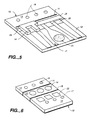
- a printhead of a thermal inkjet printer includes a flexible substrate 10 having at least one fold means 11 that allows a first section 12 of the substrate 10 to be folded over a second section 13.
- the fold means 11 can comprise spaced-apart perforations that extend completely through the substrate ( Figure 2) or, alternatively, spaced-apart slot-like depressions or apertures that extend only partway through the substrate.
- the perforations or depressions can have circular, diamond, hexagonal or other shapes that promote hinge formation along a predetermined straight line.
- the perforations can comprise 100 ⁇ m diameter apertures with their centers spaced about 150 ⁇ m apart.
- the perforations can have elongated hexagonal shapes that have a length of 200 ⁇ m and an aspect ratio of about 3:1 with centers about 250 ⁇ m apart.
- UPILEX polyimide material
- the two substrate sections can be folded to overlie each other as shown in Figures 3 and 4.
- the resulting structure can be said to be monolithic because both the substrate and the orifice plate are formed of the same material.
- the substrate 10 comprises a polymer material ranging in thickness from about 1 to 5 mils.
- the polymer can comprise a plastic such as polyimide, teflon, polyamide, polymethylmethacrylate, polyethyleneterephthalate (PET) or mixtures thereof.
- the told means 11 preferably is fabricated by laser ablation, using an excimer laser.
- At least one inkdrop ejection chamber 14 is formed on the surface of the substrate section 13, and at least one ink inlet aperture 17 is formed through the substrate section 12. It should be noted that the ink inlet aperture 17 is positioned to be in fluid communication with the inkdrop ejection chamber 14 when the two sections 12, 13 are folded over each other as shown in Figures 3 and 4.
- At least one ink outlet orifice 18 is formed through second substrate section 13, i.e., on the side of the fold means 11 opposite the laser ablated ink inlet apertures 17.
- the ink outlet orifice 18 is located to be in fluid flow communication with the inkdrop ejection chamber 14 when the first and second sections are folded over each other.
- the ink inlet apertures 17, the ink outlet apertures 18, and the perforations for the fold means 11 can be formed at the same time. In practice, this is done by using a suitable mask and a single food exposure to laser energy. Normally, thin film resistors 22 are formed on substrate 10 prior to forming the apertures; thus, when the mask has been aligned relative to the resistors, all of the apertures formed by the exposure through the mask will be in proper alignment.
- thin film conductor lines 21, a thin film common conductor line 23 and a barrier means 24 are formed on substrate 10.
- the resistors 22 and the outlet apertures 18 are located such that the told means 11 is spaced substantially from the thin film areas.
- the barrier means 24 is fabricated as a dry film barrier; alternatively, however, the barrier means can comprise a photo-ablated region on the substrate 10. In either case, the inkdrop ejection chamber 14 is defined by the barrier means 24.
- the above-described folded assembly can be connected to an inkjet pen body either with the resistors 22 facing towards or away from the pen body.
- the ink inlets can be used as ink outlets and the ink outlets can be used as ink inlets.
- the orifices 17 and 18 can be used interchangeably as ink inlets or ink outlets.
- the substrate 10 includes a first section 12 including resistors 22 and a second section 13 including outlet apertures 18.
- the substrate 10 is foldable along the fold means 11 such that the outlet apertures 18 register with the resistors 22.
- a single ink inlet aperture 26 supplies ink to more than one inkdrop ejection chamber.
- the barrier means is utilized to define the ink ejection chamber as before and also to define a common ink manifold area.
- the conductor lines 21 and common conductor 23 complete the electrical means for heating the resistors 22.
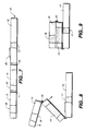
- the flexible substrate 10 includes a second fold means 19 that defines a third section 20 of the substrate 10.
- the first told means 11 separates sections 13 and 20 of the substrate 10
- the second fold means 19 separates the sections 20 and 12.
- the first section 12 includes ink inlets 17 and resistors 22
- the second section 13 includes ink outlets 18, and the third section 20 includes inkdrop ejection chambers 14.
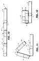
- FIGs 6 and 7 can be folded in various ways to form a monolithic inkjet printhead.
- the section 13 can be folded to overlay the third section 20 with the third section 20 being between the first and second sections 12, 13. It may be noted that, prior to folding, the third section 20 is between the first and second sections 12, 13.
- the second section 13 is located between the third and first sections 20, 12 prior to folding the substrate 10.
- the substrate 10 is folded such that the third section 20 fits between the first and second sections 12, 13.
- the fold means 11 can be formed by electroforming techniques applied to metals rather than laser ablation of plastic materials.
- the above-described methods can be employed for fabricating various devices, other than inkjet printheads, where it is important the components be carefully aligned in relationship to each other and where it would be beneficial to form the components on a single substrate.
Landscapes
- Engineering & Computer Science (AREA)
- Manufacturing & Machinery (AREA)
- Physics & Mathematics (AREA)
- Optics & Photonics (AREA)
- Particle Formation And Scattering Control In Inkjet Printers (AREA)
Applications Claiming Priority (2)
| Application Number | Priority Date | Filing Date | Title |
|---|---|---|---|
| US868355 | 1986-05-29 | ||
| US86835592A | 1992-04-02 | 1992-04-02 |
Publications (2)
| Publication Number | Publication Date |
|---|---|
| EP0564295A1 true EP0564295A1 (fr) | 1993-10-06 |
| EP0564295B1 EP0564295B1 (fr) | 1996-03-13 |
Family
ID=25351510
Family Applications (1)
| Application Number | Title | Priority Date | Filing Date |
|---|---|---|---|
| EP93302603A Expired - Lifetime EP0564295B1 (fr) | 1992-04-02 | 1993-04-01 | Tête d'impression et son procédé de fabrication |
Country Status (4)
| Country | Link |
|---|---|
| US (1) | US5453769A (fr) |
| EP (1) | EP0564295B1 (fr) |
| JP (1) | JP3308337B2 (fr) |
| DE (1) | DE69301746T2 (fr) |
Cited By (3)
| Publication number | Priority date | Publication date | Assignee | Title |
|---|---|---|---|---|
| DE4336416A1 (de) * | 1993-10-19 | 1995-08-24 | Francotyp Postalia Gmbh | Face-Shooter-Tintenstrahldruckkopf und Verfahren zu seiner Herstellung |
| US7084007B2 (en) * | 2001-03-07 | 2006-08-01 | Hewlett-Packard Development Company, L.P. | Fabrication and assembly structures and methods for memory devices |
| EP1710083A1 (fr) * | 2005-04-07 | 2006-10-11 | Xerox Corporation | Plaque à diaphragme avec sortie partiellement gravée |
Families Citing this family (15)
| Publication number | Priority date | Publication date | Assignee | Title |
|---|---|---|---|---|
| EP0594310A3 (en) * | 1992-10-23 | 1994-08-17 | Hewlett Packard Co | Ink jet printhead and method of manufacture thereof |
| JP3422342B2 (ja) * | 1994-03-28 | 2003-06-30 | セイコーエプソン株式会社 | インクジェツト式記録ヘツド |
| US6003977A (en) * | 1996-02-07 | 1999-12-21 | Hewlett-Packard Company | Bubble valving for ink-jet printheads |
| US5818478A (en) * | 1996-08-02 | 1998-10-06 | Lexmark International, Inc. | Ink jet nozzle placement correction |
| US5935430A (en) * | 1997-04-30 | 1999-08-10 | Hewlett-Packard Company | Structure for capturing express transient liquid phase during diffusion bonding of planar devices |
| US5888390A (en) * | 1997-04-30 | 1999-03-30 | Hewlett-Packard Company | Multilayer integrated assembly for effecting fluid handling functions |
| US5997708A (en) * | 1997-04-30 | 1999-12-07 | Hewlett-Packard Company | Multilayer integrated assembly having specialized intermediary substrate |
| US5792943A (en) * | 1997-04-30 | 1998-08-11 | Hewlett-Packard Company | Planar separation column for use in sample analysis system |
| US5988786A (en) * | 1997-06-30 | 1999-11-23 | Hewlett-Packard Company | Articulated stress relief of an orifice membrane |
| TW369485B (en) * | 1998-07-28 | 1999-09-11 | Ind Tech Res Inst | Monolithic producing method for chip of ink-jet printing head |
| US6158712A (en) * | 1998-10-16 | 2000-12-12 | Agilent Technologies, Inc. | Multilayer integrated assembly having an integral microminiature valve |
| US6467878B1 (en) | 2000-05-10 | 2002-10-22 | Hewlett-Packard Company | System and method for locally controlling the thickness of a flexible nozzle member |
| EP1666256B1 (fr) * | 2000-08-09 | 2007-05-23 | Sony Corporation | Tête d'impression, son procédé de fabrication et imprimante |
| US6701593B2 (en) * | 2001-01-08 | 2004-03-09 | Nanodynamics, Inc. | Process for producing inkjet printhead |
| JP5332293B2 (ja) * | 2008-04-25 | 2013-11-06 | セイコーエプソン株式会社 | 液滴吐出ヘッド及び液滴吐出ヘッドの製造方法 |
Citations (3)
| Publication number | Priority date | Publication date | Assignee | Title |
|---|---|---|---|---|
| GB2009049A (en) * | 1977-12-06 | 1979-06-13 | Philips Nv | Electrostatic write head and method of manufacturing this head |
| EP0352468A2 (fr) * | 1988-06-21 | 1990-01-31 | Canon Kabushiki Kaisha | Procédé de fabrication d'une plaque à tuyères pour une tête d'imprimante à jet d'encre |
| EP0471157A1 (fr) * | 1990-08-16 | 1992-02-19 | Hewlett-Packard Company | Composants obtenus par photo-ablation pour tête d'impression à jet d'encre |
Family Cites Families (8)
| Publication number | Priority date | Publication date | Assignee | Title |
|---|---|---|---|---|
| US3626143A (en) * | 1969-04-02 | 1971-12-07 | American Can Co | Scoring of materials with laser energy |
| US4287525A (en) * | 1977-09-21 | 1981-09-01 | Sharp Kabushiki Kaisha | Multi-pin record electrode assembly and driving method of the same |
| US4314259A (en) * | 1980-06-16 | 1982-02-02 | Arthur D. Little, Inc. | Apparatus for providing an array of fine liquid droplets particularly suited for ink-jet printing |
| JPS61242852A (ja) * | 1985-04-19 | 1986-10-29 | Hitachi Koki Co Ltd | インクジエツトヘツドの製造方法 |
| DE3824654A1 (de) * | 1988-07-20 | 1990-02-01 | Ibm Deutschland | Elektronische baueinheit |
| US5008496A (en) * | 1988-09-15 | 1991-04-16 | Siemens Aktiengesellschaft | Three-dimensional printed circuit board |
| US5103375A (en) * | 1990-02-05 | 1992-04-07 | Motorola, Inc. | Electronic module assembly and method of manufacture |
| US5305015A (en) * | 1990-08-16 | 1994-04-19 | Hewlett-Packard Company | Laser ablated nozzle member for inkjet printhead |
-
1993
- 1993-03-31 JP JP09681893A patent/JP3308337B2/ja not_active Expired - Fee Related
- 1993-04-01 DE DE69301746T patent/DE69301746T2/de not_active Expired - Fee Related
- 1993-04-01 EP EP93302603A patent/EP0564295B1/fr not_active Expired - Lifetime
-
1994
- 1994-03-08 US US08/208,100 patent/US5453769A/en not_active Expired - Lifetime
Patent Citations (3)
| Publication number | Priority date | Publication date | Assignee | Title |
|---|---|---|---|---|
| GB2009049A (en) * | 1977-12-06 | 1979-06-13 | Philips Nv | Electrostatic write head and method of manufacturing this head |
| EP0352468A2 (fr) * | 1988-06-21 | 1990-01-31 | Canon Kabushiki Kaisha | Procédé de fabrication d'une plaque à tuyères pour une tête d'imprimante à jet d'encre |
| EP0471157A1 (fr) * | 1990-08-16 | 1992-02-19 | Hewlett-Packard Company | Composants obtenus par photo-ablation pour tête d'impression à jet d'encre |
Cited By (8)
| Publication number | Priority date | Publication date | Assignee | Title |
|---|---|---|---|---|
| DE4336416A1 (de) * | 1993-10-19 | 1995-08-24 | Francotyp Postalia Gmbh | Face-Shooter-Tintenstrahldruckkopf und Verfahren zu seiner Herstellung |
| US5752303A (en) * | 1993-10-19 | 1998-05-19 | Francotyp-Postalia Ag & Co. | Method for manufacturing a face shooter ink jet printing head |
| US5845380A (en) * | 1993-10-19 | 1998-12-08 | Francotyp-Postalia Ag & Co. | Method for manufacturing a module for shorter ink jet printing head with parallel processing of modules |
| US6070972A (en) * | 1993-10-19 | 2000-06-06 | Francotyp-Postalia Ag & Co. | Face shooter ink jet printing head |
| US7084007B2 (en) * | 2001-03-07 | 2006-08-01 | Hewlett-Packard Development Company, L.P. | Fabrication and assembly structures and methods for memory devices |
| EP1710083A1 (fr) * | 2005-04-07 | 2006-10-11 | Xerox Corporation | Plaque à diaphragme avec sortie partiellement gravée |
| US7549733B2 (en) | 2005-04-07 | 2009-06-23 | Xerox Corporation | Diaphragm plate with partially-etched port |
| CN1843761B (zh) * | 2005-04-07 | 2012-01-04 | 施乐公司 | 墨滴释放设备 |
Also Published As
| Publication number | Publication date |
|---|---|
| DE69301746T2 (de) | 1996-08-08 |
| US5453769A (en) | 1995-09-26 |
| EP0564295B1 (fr) | 1996-03-13 |
| DE69301746D1 (de) | 1996-04-18 |
| JP3308337B2 (ja) | 2002-07-29 |
| JPH068445A (ja) | 1994-01-18 |
Similar Documents
| Publication | Publication Date | Title |
|---|---|---|
| EP0564295B1 (fr) | Tête d'impression et son procédé de fabrication | |
| US5305018A (en) | Excimer laser-ablated components for inkjet printhead | |
| EP0244214B1 (fr) | Tête d'impression à jet d'encre thermique | |
| US5635966A (en) | Edge feed ink delivery thermal inkjet printhead structure and method of fabrication | |
| EP0303350B1 (fr) | Formation de gouttelettes au moyen d'une tuyère déplacée | |
| JPH11129482A (ja) | インクジェットプリントヘッド及びフィルタ要素の製造方法 | |
| EP0564072B1 (fr) | Tête d'impression à jet d'encre avec acheminement efficace des conducteurs | |
| GB2267255A (en) | ink-throttling arrangements in an ink-jet printer. | |
| JPH03182359A (ja) | サーマル・インク・ジェット・プリントヘッドの製造方法 | |
| JP2002500117A (ja) | 印刷ヘッド用ノズル・アレイ | |
| JPH11320889A (ja) | 薄膜インクジェットプリントヘッド | |
| US6142611A (en) | Oxide island structure for flexible inkjet printhead and method of manufacture thereof | |
| US6368515B1 (en) | Method of manufacturing ink-jet printer head | |
| EP0110534B1 (fr) | Combinaison monolithe avec plaque d'orifices à jet d'encre et résistance | |
| US6350018B1 (en) | Ink jet drop ejection architecture for improved damping and process yield | |
| US6231165B1 (en) | Inkjet recording head and inkjet apparatus provided with the same | |
| US20050206679A1 (en) | Fluid ejection assembly | |
| JPH11334079A (ja) | インクジェットヘッド及びその製造方法 | |
| JPH0924612A (ja) | インクジェットヘッド | |
| KR100450779B1 (ko) | 버블제트프린터 | |
| JP2000190499A (ja) | トップシュ―タ型サ―マルインクジェットヘッド | |
| US20020180838A1 (en) | Barrier adhesion by patterning gold | |
| JP2000006409A (ja) | サーマルインクジェットヘッド | |
| JP2000015816A (ja) | インクジェットヘッド及びその製造方法 | |
| JPH11334080A (ja) | サーマルインクジェットヘッド及びその製造方法 |
Legal Events
| Date | Code | Title | Description |
|---|---|---|---|
| PUAI | Public reference made under article 153(3) epc to a published international application that has entered the european phase |
Free format text: ORIGINAL CODE: 0009012 |
|
| AK | Designated contracting states |
Kind code of ref document: A1 Designated state(s): DE FR GB |
|
| 17P | Request for examination filed |
Effective date: 19931220 |
|
| 17Q | First examination report despatched |
Effective date: 19950413 |
|
| GRAA | (expected) grant |
Free format text: ORIGINAL CODE: 0009210 |
|
| AK | Designated contracting states |
Kind code of ref document: B1 Designated state(s): DE FR GB |
|
| REF | Corresponds to: |
Ref document number: 69301746 Country of ref document: DE Date of ref document: 19960418 |
|
| ET | Fr: translation filed | ||
| PLBE | No opposition filed within time limit |
Free format text: ORIGINAL CODE: 0009261 |
|
| STAA | Information on the status of an ep patent application or granted ep patent |
Free format text: STATUS: NO OPPOSITION FILED WITHIN TIME LIMIT |
|
| 26N | No opposition filed | ||
| REG | Reference to a national code |
Ref country code: GB Ref legal event code: 732E |
|
| REG | Reference to a national code |
Ref country code: FR Ref legal event code: TP |
|
| REG | Reference to a national code |
Ref country code: GB Ref legal event code: IF02 |
|
| PGFP | Annual fee paid to national office [announced via postgrant information from national office to epo] |
Ref country code: DE Payment date: 20050531 Year of fee payment: 13 |
|
| PG25 | Lapsed in a contracting state [announced via postgrant information from national office to epo] |
Ref country code: DE Free format text: LAPSE BECAUSE OF NON-PAYMENT OF DUE FEES Effective date: 20061101 |
|
| PGFP | Annual fee paid to national office [announced via postgrant information from national office to epo] |
Ref country code: GB Payment date: 20110426 Year of fee payment: 19 |
|
| REG | Reference to a national code |
Ref country code: GB Ref legal event code: 732E Free format text: REGISTERED BETWEEN 20120329 AND 20120404 |
|
| PGFP | Annual fee paid to national office [announced via postgrant information from national office to epo] |
Ref country code: FR Payment date: 20120503 Year of fee payment: 20 |
|
| GBPC | Gb: european patent ceased through non-payment of renewal fee |
Effective date: 20120401 |
|
| PG25 | Lapsed in a contracting state [announced via postgrant information from national office to epo] |
Ref country code: GB Free format text: LAPSE BECAUSE OF NON-PAYMENT OF DUE FEES Effective date: 20120401 |