EP1710102B1 - Amortisseur réglable - Google Patents
Amortisseur réglable Download PDFInfo
- Publication number
- EP1710102B1 EP1710102B1 EP06251804A EP06251804A EP1710102B1 EP 1710102 B1 EP1710102 B1 EP 1710102B1 EP 06251804 A EP06251804 A EP 06251804A EP 06251804 A EP06251804 A EP 06251804A EP 1710102 B1 EP1710102 B1 EP 1710102B1
- Authority
- EP
- European Patent Office
- Prior art keywords
- rod
- plunger
- adjuster
- shock absorber
- pneumatic actuator
- Prior art date
- Legal status (The legal status is an assumption and is not a legal conclusion. Google has not performed a legal analysis and makes no representation as to the accuracy of the status listed.)
- Expired - Lifetime
Links
Images



Classifications
-
- F—MECHANICAL ENGINEERING; LIGHTING; HEATING; WEAPONS; BLASTING
- F16—ENGINEERING ELEMENTS AND UNITS; GENERAL MEASURES FOR PRODUCING AND MAINTAINING EFFECTIVE FUNCTIONING OF MACHINES OR INSTALLATIONS; THERMAL INSULATION IN GENERAL
- F16F—SPRINGS; SHOCK-ABSORBERS; MEANS FOR DAMPING VIBRATION
- F16F9/00—Springs, vibration-dampers, shock-absorbers, or similarly-constructed movement-dampers using a fluid or the equivalent as damping medium
- F16F9/32—Details
- F16F9/44—Means on or in the damper for manual or non-automatic adjustment; such means combined with temperature correction
- F16F9/46—Means on or in the damper for manual or non-automatic adjustment; such means combined with temperature correction allowing control from a distance, i.e. location of means for control input being remote from site of valves, e.g. on damper external wall
- F16F9/461—Means on or in the damper for manual or non-automatic adjustment; such means combined with temperature correction allowing control from a distance, i.e. location of means for control input being remote from site of valves, e.g. on damper external wall characterised by actuation means
-
- B—PERFORMING OPERATIONS; TRANSPORTING
- B60—VEHICLES IN GENERAL
- B60G—VEHICLE SUSPENSION ARRANGEMENTS
- B60G17/00—Resilient suspensions having means for adjusting the spring or vibration-damper characteristics, for regulating the distance between a supporting surface and a sprung part of vehicle or for locking suspension during use to meet varying vehicular or surface conditions, e.g. due to speed or load
- B60G17/06—Characteristics of dampers, e.g. mechanical dampers
- B60G17/08—Characteristics of fluid dampers
-
- B—PERFORMING OPERATIONS; TRANSPORTING
- B60—VEHICLES IN GENERAL
- B60G—VEHICLE SUSPENSION ARRANGEMENTS
- B60G2500/00—Indexing codes relating to the regulated action or device
- B60G2500/10—Damping action or damper
- B60G2500/104—Damping action or damper continuous
Definitions
- the subject invention is directed to a shock absorber assembly including an adjustment mechanism for adjusting damping characteristics, which is controlled by an actuator with a restrictor that meters air flow from a compressed air source.
- Air suspensions include numerous air springs and shock absorbers that are used to improve vehicle ride characteristics by accommodating variations in road surfaces. Air suspensions are common in high load capacity applications, such as heavy-duty line haul applications for example, where cargo loads can vary significantly. Significant load variations can adversely affect ride quality.
- the internal valve assembly defines an effective area on which the air pressure signal can act. Due to the position of the internal valve assembly within the hollow rod, this effective area is relatively small. This means that the force acting on the internal valve assembly is not always adequate to overcome valve seal friction and often cannot hold a desired valve setting. Thus, there is a need for a pneumatic actuator for a shock absorber adjustment mechanism that can more effectively and efficiently control damping adjustment, as well as overcoming the other above-mentioned deficiencies in the prior art.
- US3146862 discloses a shock absorber where damping fluid is displaced by means of a damping piston.
- a shock absorber includes an adjustment mechanism that adjusts damping forces within the shock absorber in response to predetermined input conditions.
- a pneumatic actuator controls movement of the adjustment mechanism.
- the pneumatic actuator is fluidly connected to a pressurized air source with a fitting assembly that meters air flow to attenuate pressure spikes.
- the shock absorber is used in a vehicle suspension system that includes at least one suspension air bag.
- the suspension air bag is pressurized and thus provides a compressed air source for the pneumatic actuator.
- the fitting assembly includes a main fitting body that fluidly connects an end mount of the shock absorber to the compressed air source.
- the main fitting body has an inner bore that is defined by an inner diameter.
- a restrictor plug is received within the inner bore and is defined by an outer diameter.
- the main fitting body and the restrictor plug cooperate to provide a reduced area flow passage that is defined between the outer diameter of the restrictor plug and the inner diameter of the main fitting body. This reduced area flow passage meters air flow from the compressed air source to the adjustment mechanism and attenuates air pressure spikes resulting from suspension travel.
- the shock absorber includes a main rod that supports a piston for axial movement within a cylinder body.
- the piston separates the cylinder body into first and second fluid chambers.
- the adjustment mechanism includes an adjustment rod that is received within an axial bore formed within the main rod. The adjustment rod is axially moved within the axial bore by the pneumatic actuator to uncover and cover a plurality of radial holes that are in fluid communication with at least one of the first and second fluid chambers.
- the pneumatic actuator includes a plunger having at least one tapered surface that engages the adjuster rod to move the adjuster rod in a desired direction. At least one spring resiliently biases the plunger to a soft, or lower damping force, position.
- the plunger includes a pair of legs with opposing tapered surfaces. The opposing tapered surfaces cooperate with the adjuster rod to move the adjuster rod back and forth within the main rod between soft and hard damping positions.
- the plunger comprises a conical body that cooperates with the adjuster rod to move the adjuster rod from a soft position to a hard position. In this example, another spring is required to resiliently bias the adjuster rod to the soft position.
- the subject invention provides a pneumatic actuator for a shock absorber adjustment mechanism that more effectively and efficiently controls damping adjustment by metering air flow to the pneumatic actuator.
- the pneumatic actuator exposes an increased effective area to a pressurized air source to ensure that forces acting on a piston valve assembly are adequate to overcome valve seal friction and can hold a desired valve setting.
- the angular relationship between the pneumatic actuator and the adjuster rod provides a mechanical advantage to the pneumatic actuator that favors the plunger moving the adjuster rod, but wherein the adjuster rod cannot move the plunger.
- a vehicle suspension assembly 10 includes air springs 12, 14 that are supported on a suspension arrangement 16 in a conventional manner.
- the air springs 12, 14 are pressurized with air in a known manner.
- Shock absorbers 18 provide further damping to absorb relative movement between vehicle wheels 20 and a vehicle body structure 22.
- Each of the shock absorbers 18 includes the ability to provide adjustable damping that is responsive to changes in loading on the vehicle body structure 22.
- the adjustment is controlled by a pneumatic actuator 24, see Figure 2 , which is fluidly connected by an air coupling or fitting 32 to a pressurized air source.
- the pressurized air source comprises at least one of the air springs 12, 14.
- One end 26 of the shock absorber 18 is connected with the vehicle body structure 22 while an opposite end 28 is connected with an appropriate portion of an axle assembly 30.
- the vehicle body structure 22 comprises the sprung mass and the axle assembly 30 comprises the unsprung mass.
- the fitting 32 is secured to the one end 26 of the shock absorber 18.
- An air hose or conduit 34 couples the fitting 32 with an air supply 36 that couples a leveling valve or an air pressure source 38 with the air springs 12, 14. Pressurized air from the air springs 12, 14 is communicated to the pneumatic actuator 24 to adjust damping forces within the shock absorber 18. This will be discussed in greater detail below.
- the shock absorber 18 includes an outer cylinder 40 and an inner cylinder 42 having one end portion received within the outer cylinder 40.
- a piston assembly 44 is received within the inner cylinder 42 and separates the shock absorber 18 into a compression chamber 46 and a rebound chamber 48.
- the piston assembly 44 is coupled to a main rod 50 that extends into the outer cylinder 40.
- the main rod 50 defines an axis A along which the main rod and piston assembly 44 move to achieve damping.
- the main rod 50 has a first rod end mount 52 that is coupled to the vehicle body structure 22.
- the outer cylinder 40 has a second rod end mount 54 that is coupled to the vehicle wheel 20.
- the main rod 50 has a first rod end portion 56 that is coupled to the piston assembly 44 and a second rod end portion 58 that extends into the first rod end mount 52.
- the main rod 50 includes an axial bore 60 that extends along a length of the main rod 50.
- An adjuster rod 62 is received within the axial bore 60. Movement of the adjuster rod 62 is controlled by the pneumatic actuator 24. The adjuster rod 62 cooperates with the piston assembly 44 and main rod 50 to adjust damping in response to variations in loading on the vehicle. This will be discussed in greater detail below.
- An optional dust tube 64 can also be utilized on the shock absorber 18. The dust tube 64 protects the main rod 50 from being impacted by external debris.
- An interface between the adjuster rod 62 and piston assembly 44 is shown in greater detail in Figure 3 .
- the piston assembly 44 includes a piston 66 that engages an inner surface of the inner cylinder 42. A seal 68 surrounds the piston 66 to prevent leaking between the rebound 48 and compression 46 chambers.
- the piston 66 is supported on a piston rod adapter 70 that is secured to the main rod 50.
- the piston 66 includes a plurality of passages 72 that extend between the compression chamber 46 and the rebound chamber 48.
- At least one recoil disc 74 is positioned on a compression side of the piston 66.
- a washer 76 and nut 78 hold the recoil disc 74 against the compression side of the piston 66.
- At least one compression disc 80 is positioned on a rebound side of the piston 66.
- a top-out washer 82 is positioned between an end of the main rod 50 and the compression disc 80.
- a plurality of shims 84 is positioned between the compression disc 80 and the top-out washer 82. The top-out washer 82 and shims 84 cooperate to provide a compression disc limiter.
- the recoil disc 74 and compression disc 80 operate in a known manner and cooperate with the passages 72 in the piston 66 to control damping. Fluid flows through the passages 72 and across the recoil 74 and compression 80 discs to provide the damping. In addition to preventing leaking, the seal 68 ensures correct oil flow through the piston 66, passages 72, and across the recoil 74 and compression 80 discs.
- An inner cylinder head 86 is coupled to one end of the main rod 50.
- the inner cylinder head 86 includes a cylinder head adapter 88 that couples the inner cylinder head 86 to the inner cylinder 42.
- the cylinder head adapter 88 can be a separate component or can be formed with the inner cylinder head 86 as one-piece.
- the inner cylinder head 86 provides a rod guide bearing surface.
- a nut 90 is used to secure a top-out washer 92 against the inner cylinder head 86.
- the nut 90 is threaded onto the main rod 50.
- the top-out washer 92 serves as a restrictor that defines a limit for movement of the main rod 50, but also provides hydraulic cushioning at full extension as top-out washer 92 engages with the cylinder head adapter 88.
- the inner cylinder head 86 is received within an intermediate cylinder head 94.
- a seal 96 is positioned between an inner surface of the intermediate cylinder head 94 and an outer surface of the main rod 50 and is held in place with a first retainer 98.
- the piston rod adapter 70 includes a plurality of radial holes 102 (only one is shown) that are covered and uncovered by the adjuster rod 62 to adjust damping. Preferably, there are four (4) radial holes 102, however, more or less holes could be utilized.
- the adjuster rod 62 moves back and forth along a linear path within the axial bore 60. As discussed above, axial movement of the adjuster rod 62 is controlled by the pneumatic actuator 24.
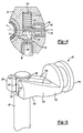
- the pneumatic actuator 24 is shown in greater detail in Figure 4 .
- the first rod end mount 52 includes a cavity 110 that receives the fitting 32.
- the pneumatic actuator 24 includes a plunger 112 that cooperates with one end 114 of the adjuster rod 62 to move the adjuster rod 62 in an axial direction along axis A.
- the plunger 112 includes a base piston portion 116 and an extension body member 118 extending out from the base piston portion 116 toward the adjuster rod 62.
- a preloaded return spring 120 resiliently biases the plunger 112 in a soft or low damping position.
- the extension body member 118 includes first 120 and second 122 legs that are separated by a recess 124.
- the adjuster rod 62 is received in the recess 124.
- the adjuster rod 62 includes a groove 126 in which the first 120 and second 122 legs engage.
- Each of the first 120 and second 122 legs includes a first tapered surface 128 that engages a first adjuster rod surface 130 to move the adjuster rod 62 in a first axial direction.
- Each of the first 120 and second 122 legs also includes a second tapered surface 132 that engages a second adjuster rod surface 134 to move the adjuster rod 62 in a second axial direction opposite from the first axial direction.
- the plunger 112 can bi-directly control axial movement of the adjuster rod 62. This eliminates the need for an adjuster rod return spring.
- the radial holes 102 in the piston rod adaptor 70 are covered and uncovered to adjust damping, see Figure 3 .
- the adjuster rod 62 is pushed by the plunger 112 in an axial direction toward the vehicle wheel 20, which causes the radial holes 102 to be covered, which increases damping.
- pressure in the air springs 12, 14 decreases and the plunger 112 moves the adjuster rod 62 in a direction away from the vehicle wheel 20 to uncover the radial holes 102 and decrease damping.
- the first rod end mount 52 includes a cavity 140 that receives a plunger 142.
- the plunger 142 includes a main piston base 144 and a body member 146 extending out from the main piston base 144 toward the adjuster rod 62.
- the body member 146 includes a tapered surface 148 that cooperates with an end portion 150 of the adjuster rod 62 to move the adjuster rod 62 in an axial direction along axis A.
- the body member 146 has a conical shape.
- the plunger 142 in this example is biased in the soft position by a first return spring 152.
- the adjuster rod 62 is biased in the soft position by a second return spring 154.
- the adjuster rod 62 is sealed below the second return spring 154 with a seal 156 to prevent leakage.
- the second return spring 154 is shown at a top portion of the adjuster rod 62, however, the second return spring 154 could optionally be positioned at a bottom portion of the adjuster rod 62.
- the main rod 50 includes a plurality of radial holes 160 (only one is shown) that are covered and uncovered by the adjuster rod 62 to adjust damping.
- the radial holes 160 are covered and uncovered. If there is an increase in load on the vehicle, there is a corresponding increase in pressure in the air springs 12, 14. This increases stiffness of the shock absorber 18 by actuating the plunger 142 to move the adjuster rod 62 further into the main rod 50 to cover the radial holes 160.
- pressure in the air springs 12, 14 decreases and the adjuster rod 62 moves away from the vehicle wheel 20 to uncover the radial holes 160 and decrease damping.
- pneumatic actuator 24 of Figure 7 could also be used with the piston rod adaptor configuration shown in Figure 2 .
- pneumatic actuator 24 of Figure 2 could be used with the main rod configuration shown in Figure 7 .
- dust tube 64 shown in the configuration of Figure 2 could also optionally be used in the configuration of Figure 7 .
- a union fitting 170 and restrictor 172 are used to meter air flow, see Figures 8 and 9 .
- the union fitting 170 fluidly connects the fitting 32 to the compressed air source, i.e. the air springs 12,14.
- the union fitting 170 includes an internal bore 174 that is defined by an inner surface 176 having an inner diameter.
- the restrictor 172 comprises a solid plug that is received within the internal bore 174.
- the restrictor 172 includes a lip portion 178 that holds the restrictor 172 in place within the internal bore 174.
- the restrictor 172 is defined by an outer surface 180 having a diameter that is less than the inner diameter of the internal bore 174. This forms a reduced flow area 182 between the restrictor 172 and union fitting 170.
- the restrictor 172 comprises a round plug. It should be understood that the restrictor 172 can float within the internal bore 174 during operation, such that an annular or ring-shaped flow passage extends completely around the restrictor 172. When the union fitting 170 is not pressurized, gravity will cause the restrictor 172 to settle to a position such as that shown in Figure 9 , for example.
- This reduced flow area 182 provides a metered air flow through an annular area defined by an inner diameter of the union fitting 170 and an outer diameter of the restrictor 172.
- a slightly delayed signal at the pneumatic actuator 24 is acceptable. Transient air spikes are virtually eliminated by using the restrictor 172 in the union fitting 170. Thus, air pressure spikes resulting from suspension travel are easily attenuated.
- the adjuster rod 62 changes the damping forces by covering and uncovering radial holes 102, 160. Fluid flow is controlled by a piston assembly and disc valving as described above as the shock absorber moves between extended and collapsed positions. By opening and closing radial holes 102 a bypass is creased that changes rebound and compression damping simultaneously.
- Figure 2 shows the shock absorber 18 in an extended position while Figure 3 shows a collapsed position. It should be understood that the shock absorber of each configuration is movable between the collapsed and extended positions.
Landscapes
- Engineering & Computer Science (AREA)
- Mechanical Engineering (AREA)
- General Engineering & Computer Science (AREA)
- Vehicle Body Suspensions (AREA)
- Fluid-Damping Devices (AREA)
Claims (22)
- Dispositif amortisseur, comprenant .
un premier cylindre (42) ;
un piston (44) divisant ledit premier cylindre en des première et deuxième chambres (46, 48) ;
une tige principale (50) supportant ledit piston de manière mobile dans ledit premier cylindre, ladite tige principale comportant un alésage central (60) s'étendant axialement le long d'une longueur de ladite tige principale ; et
une tige d'ajustage (62) reçue à l'intérieur dudit alésage central et ayant une première portion d'extrémité de tige s'étendant vers ledit piston et une deuxième portion d'extrémité de tige s'étendant vers une fixation d'extrémité de tige (52) ;
caractérisé en ce que l'amortisseur a un deuxième cylindre (40) entourant au moins une portion dudit premier cylindre ; et
un actionneur pneumatique (24) comprenant un plongeur (112, 142) ayant une portion de base reçue à l'intérieur de ladite fixation d'extrémité de tige et ledit plongeur comportant une portion de corps réduite s'étendant vers l'extérieur depuis ladite portion de base vers ladite tige d'ajustage, ladite portion de corps réduite coopérant avec ladite deuxième portion d'extrémité de tige pour déplacer ladite tige d'ajustage à l'intérieur dudit alésage central jusqu'à une position de tige d'ajustage souhaitée afin d'ajuster les forces d'amortissement ;
et en ce que le mouvement de la tige d'ajustage réagit aux changements de pression dans un ressort pneumatique. - Dispositif amortisseur selon la revendication 1, comportant une pluralité de trous radiaux (160, 102) formés dans ladite tige principale ou dans un adaptateur de tige de piston (70), ledit actionneur pneumatique ajustant les forces d'amortissement en couvrant et en découvrant ladite pluralité de trous radiaux.
- Dispositif amortisseur selon la revendication 2, dans lequel ladite portion de corps réduite comprend des première et deuxième branches (120, 122) séparées par une ouverture en retrait (124), ladite deuxième extrémité de tige de ladite tige d'ajustage étant reçue dans ladite ouverture en retrait, et lesdites première et deuxième branches comportant chacune une première surface effilée (128) qui s'engage avec ladite tige d'ajustage pour déplacer ladite tige d'ajustage dans une première direction et une deuxième surface effilée (132) qui s'engage avec ladite tige d'ajustage pour déplacer ladite tige d'ajustage dans une deuxième direction opposée à ladite première direction.
- Dispositif amortisseur selon la revendication 2 ou 3, comportant un ressort (120, 152) sollicitant de manière élastique ledit plongeur dans une position d'amortissement douce, ledit ressort étant positionné à l'intérieur de ladite fixation d'extrémité de tige sur un côté de ladite tige d'ajustage opposé audit plongeur.
- Dispositif amortisseur selon la revendication 2, dans lequel ledit adaptateur de tige de piston (70) est accouplé audit piston, ledit adaptateur de tige de piston comportant une portion de corps s'étendant dans ledit alésage central de ladite tige principale, ladite portion de corps comportant ladite pluralité de trous radiaux (102), ledit actionneur pneumatique ajustant les forces d'amortissement en déplaçant ladite tige d'ajustage pour couvrir et découvrir ladite pluralité de trous radiaux ; le dispositif amortisseur ayant en outre
une première culasse (86) accouplée à une extrémité de la tige principale (50) et au premier cylindre (42), de telle sorte que la première culasse fournisse une surface d'appui de guidage de tige ; et
un limiteur (92) fixé contre la première culasse et configuré pour définir une limite au mouvement de la tige principale. - Dispositif amortisseur selon la revendication 2, dans lequel ladite portion de corps réduite comprend un corps conique (146) s'étendant jusqu'à une pointe effilée distale qui s'engage avec ladite deuxième portion d'extrémité de tige, et l'amortisseur comporte un premier ressort (152) pour solliciter ledit plongeur dans une position d'amortissement douce et un deuxième ressort (154) pour solliciter ladite tige d'ajustage dans une position d'amortissement douce.
- Dispositif amortisseur selon la revendication 2, dans lequel ladite tige principale comporte ladite pluralité de trous radiaux (160) et dans lequel ledit actionneur pneumatique ajuste des forces d'amortissement en déplaçant ladite tige d'ajustage de manière à ce qu'elle couvre et découvre ladite pluralité de trous radiaux.
- Dispositif amortisseur selon la revendication 2, comportant un raccord (170) adapté pour connecter fluidiquement ladite fixation d'extrémité de tige à la source d'air comprimé, ledit raccord définissant un conduit pour diriger l'air vers ledit actionneur pneumatique, de l'air comprimé s'écoulant à travers ledit conduit pour exercer une force de pression contre ladite portion de base pour déplacer ledit plongeur vers ladite tige d'ajustage pour déplacer ladite tige d'ajustage dans une direction dans ledit premier cylindre pour augmenter l'amortissement, et ledit amortisseur comportant un limiteur (172) positionné dans ledit conduit pour atténuer les pics de pression d'air en dosant le flux d'air à travers ledit raccord, et ledit limiteur comportant un bouchon inséré dans ledit raccord, qui définit une zone d'écoulement annulaire (182) entre un diamètre extérieur dudit bouchon et un diamètre intérieur dudit raccord.
- Dispositif amortisseur selon l'une quelconque des revendications précédentes, dans lequel la relation angulaire entre l'actionneur pneumatique et la tige d'ajustage fournit un avantage mécanique à l'actionneur pneumatique qui favorise le déplacement de la tige d'ajustage par le plongeur, mais dans lequel la tige d'ajustage ne peut pas déplacer le plongeur.
- Actionneur pneumatique pour ajuster l'amortissement dans un amortisseur, comprenant :un plongeur (112, 142) adapté pour s'engager avec une tige d'ajustage (62) reçue dans un alésage central (60) d'une tige de piston principale (50) ; ledit plongeur ayant une portion de base et une portion de corps réduite s'étendant vers l'extérieur depuis ladite portion de base vers ladite tige d'ajustage ;un raccord (170) pour connecter fluidiquement ledit plongeur à une source d'air comprimé, ledit raccord comportant un alésage interne (174) défini par un diamètre intérieur ; etun limiteur (172) reçu dans ledit alésage interne et ayant un diamètre extérieur, ledit limiteur définissant une zone de passage d'écoulement réduite (182) entre ledit diamètre extérieur et ledit diamètre intérieur, qui atténue les pics de pression d'air en dosant l'écoulement d'air depuis la source d'air comprimé jusqu'audit plongeur ;caractérisé en ce que le mouvement de ladite tige d'ajustage réagit aux changements de pression dans un ressort pneumatique.
- Dispositif amortisseur selon la revendication 8, ou actionneur pneumatique selon la revendication 10, dans lequel la source d'air comprimé comprend un ressort pneumatique à suspension (12, 14) ; et comprenant en outre
une première culasse (86) accouplée à une extrémité de la tige principale (50) et à un premier cylindre (42), de telle sorte que la première culasse fournisse une surface d'appui de guidage de tige ; et
un limiteur (92) fixé contre la première culasse et configuré pour définir une limite au mouvement de la tige principale. - Actionneur pneumatique selon la revendication 10 ou 11, dans lequel ledit plongeur comporte au moins une surface effilée qui s'engage avec ladite tige d'ajustage pour déplacer ladite tige d'ajustage axialement à l'intérieur de l'alésage central.
- Actionneur pneumatique selon la revendication 10 ou 11 ou 12, comportant une fixation d'extrémité d'amortisseur (52) ayant une cavité (110, 140) avec un orifice d'entrée, ledit raccord étant accouplé audit orifice d'entrée et ledit plongeur étant reçu à l'intérieur de ladite cavité entre ledit raccord et ladite tige d'ajustage.
- Actionneur pneumatique selon l'une quelconque des revendications 11 à 13, dans lequel la relation angulaire entre l'actionneur pneumatique et ladite tige d'ajustage fournit un avantage mécanique à l'actionneur pneumatique qui favorise le déplacement de ladite tige d'ajustage par le plongeur, mais dans lequel ladite tige d'ajustage ne peut pas déplacer le plongeur.
- Système de suspension de véhicule, comprenant :au moins un coussin d'air de suspension (12, 14) sous pression ;au moins un composant de suspension (16) pour supporter ledit au moins un coussin d'air de suspension ; etau moins un amortisseur (18) comportant une tige principale (50) qui se déplace axialement à l'intérieur dudit au moins un amortisseur, ladite tige principale comportant un alésage central (60) pour recevoir une tige d'ajustage ;caractérisé en ce que le système de suspension a un actionneur pneumatique connecté fluidiquement audit au moins un coussin d'air de suspension, ledit actionneur pneumatique comportant un plongeur (112, 142), qui déplace ladite tige d'ajustage à l'intérieur dudit alésage central pour ajuster des forces d'amortissement, ledit plongeur ayant une portion de base et une portion de corps réduite s'étendant vers l'extérieur depuis ladite portion de base vers ladite tige d'ajustageet en ce que le mouvement de ladite tige d'ajustage réagit aux changements de pression dans un ressort pneumatique.
- Système de suspension de véhicule selon la revendication 15, dans lequel ledit au moins un amortisseur comporte une première fixation d'extrémité de tige adaptée pour être accouplée à un corps de véhicule et comportant une deuxième fixation d'extrémité de tige (54) adaptée pour être accouplée à une roue de véhicule, ladite première fixation d'extrémité de tige comportant une cavité (110, 140) avec un orifice d'entrée en communication fluidique avec ledit au moins un coussin d'air de suspension, ledit plongeur étant reçu dans ladite cavité et une augmentation de pression dans ledit au moins un coussin d'air de suspension résultant en une augmentation de la pression d'air au niveau dudit orifice d'entrée, qui déplace ladite tige d'ajustage pour augmenter les forces d'amortissement à l'intérieur de l'au moins un amortisseur ; et ayant en outre une première culasse (86) accouplée à une extrémité de la tige principale (50) et à un premier cylindre (42), de telle sorte que la première culasse fournisse une surface d'appui de guidage de tige ; et
un limiteur (92) fixé contre la première culasse et configuré pour définir une limite au mouvement de la tige principale. - Système de suspension de véhicule selon la revendication 16, comportant un raccord (170) reliant fluidiquement ladite première fixation d'extrémité de tige audit au moins un coussin d'air de suspension, ledit raccord comportant un alésage interne (174) défini par un diamètre intérieur, et comportant un limiteur (172) reçu à l'intérieur dudit alésage interne et ayant un diamètre extérieur, ledit limiteur définissant une zone de passage d'écoulement réduite (182) entre ledit diamètre extérieur et ledit diamètre intérieur, qui atténue les pics de pression d'air résultant de la course de suspension en dosant l'écoulement d'air depuis ledit au moins un coussin d'air de suspension vers ledit plongeur.
- Suspension de véhicule selon l'une quelconque des revendications 15 à 17, dans laquelle la relation angulaire entre l'actionneur pneumatique et ladite tige d'ajustage fournit un avantage mécanique à l'actionneur pneumatique qui favorise le déplacement de ladite tige d'ajustage par le plongeur mais dans laquelle ladite tige d'ajustage ne peut pas déplacer le plongeur.
- Actionneur pneumatique selon la revendication 12, comportant une pluralité de trous radiaux (160, 102) formés dans ladite tige de piston principale ou dans un adaptateur de tige de piston (70), dans lequel l'actionneur pneumatique ajuste les forces d'amortissement en couvrant et en découvrant ladite pluralité de trous radiaux.
- Actionneur pneumatique selon la revendication 12, dans lequel ladite surface d'extrémité distale dudit plongeur comprend l'une d'une paire de branches (120, 122) devant être apte à s'engager avec une gorge (126) formée à l'intérieur de la tige d'ajustage et d'une pointe conique (146) devant coulisser le long de la surface latérale de la tige d'ajustage.
- Système de suspension de véhicule selon la revendication 16, comportant une pluralité de trous radiaux (160, 102) formés dans l'un de ladite tige principale et d'un adaptateur de tige de piston (70), et dans lequel ledit plongeur ajuste les forces d'amortissement en couvrant et découvrant ladite pluralité de trous radiaux.
- Système de suspension de véhicule selon la revendication 16, dans lequel ladite surface d'extrémité distale dudit plongeur comprend l'une d'une paire de branches (120, 122) étant apte à s'engager avec une gorge formée à l'intérieur de ladite tige d'ajustage et d'une pointe conique (146) qui glisse le long de ladite surface latérale de ladite tige d'ajustage.
Applications Claiming Priority (1)
| Application Number | Priority Date | Filing Date | Title |
|---|---|---|---|
| US11/100,724 US7320387B2 (en) | 2005-04-06 | 2005-04-06 | Load adaptive damper with transient air signal restrictor |
Publications (2)
| Publication Number | Publication Date |
|---|---|
| EP1710102A1 EP1710102A1 (fr) | 2006-10-11 |
| EP1710102B1 true EP1710102B1 (fr) | 2012-01-11 |
Family
ID=36602495
Family Applications (1)
| Application Number | Title | Priority Date | Filing Date |
|---|---|---|---|
| EP06251804A Expired - Lifetime EP1710102B1 (fr) | 2005-04-06 | 2006-03-31 | Amortisseur réglable |
Country Status (2)
| Country | Link |
|---|---|
| US (1) | US7320387B2 (fr) |
| EP (1) | EP1710102B1 (fr) |
Families Citing this family (24)
| Publication number | Priority date | Publication date | Assignee | Title |
|---|---|---|---|---|
| WO2009073810A2 (fr) * | 2007-12-05 | 2009-06-11 | Pacific Scientific Company | Vanne d'amortissement |
| US11306798B2 (en) | 2008-05-09 | 2022-04-19 | Fox Factory, Inc. | Position sensitive suspension damping with an active valve |
| US10060499B2 (en) | 2009-01-07 | 2018-08-28 | Fox Factory, Inc. | Method and apparatus for an adjustable damper |
| US9452654B2 (en) | 2009-01-07 | 2016-09-27 | Fox Factory, Inc. | Method and apparatus for an adjustable damper |
| US20100170760A1 (en) | 2009-01-07 | 2010-07-08 | John Marking | Remotely Operated Bypass for a Suspension Damper |
| US8240329B1 (en) | 2008-11-14 | 2012-08-14 | Robust Systems Solutions, LLC | Fluid control valve |
| US10036443B2 (en) | 2009-03-19 | 2018-07-31 | Fox Factory, Inc. | Methods and apparatus for suspension adjustment |
| US9528565B2 (en) | 2014-09-16 | 2016-12-27 | Fox Factory, Inc. | Adjustable internal bypass |
| US12122205B2 (en) * | 2009-01-07 | 2024-10-22 | Fox Factory, Inc. | Active valve for an internal bypass |
| US11299233B2 (en) | 2009-01-07 | 2022-04-12 | Fox Factory, Inc. | Method and apparatus for an adjustable damper |
| MX2011010753A (es) * | 2009-04-16 | 2012-01-12 | Oneiric Systems Inc | Amortiguador que tiene flujo de fluido unidireccional. |
| US9222538B2 (en) | 2009-04-16 | 2015-12-29 | Oneiric Systems, Inc. | Shock absorber having unidirectional fluid flow |
| EP2312180B1 (fr) | 2009-10-13 | 2019-09-18 | Fox Factory, Inc. | Appareil pour contrôler un amortisseur hydraulique |
| US8886402B1 (en) | 2010-04-22 | 2014-11-11 | Armorworks Enterprises LLC | Actively variable shock absorbing strut and system |
| US9593736B2 (en) * | 2011-03-14 | 2017-03-14 | Sram, Llc | Control assembly for a bicycle shock absorber |
| EP3567272B1 (fr) | 2011-09-12 | 2021-05-26 | Fox Factory, Inc. | Procédés et appareil de réglage de suspension |
| US10330171B2 (en) | 2012-05-10 | 2019-06-25 | Fox Factory, Inc. | Method and apparatus for an adjustable damper |
| US8991840B2 (en) | 2013-03-14 | 2015-03-31 | Oshkosh Defense, Llc | Load dependent damper for a vehicle suspension system |
| ES2773304T3 (es) * | 2014-01-21 | 2020-07-10 | Safran Landing Systems Uk Ltd | Conjunto amortiguador |
| EP3280676B1 (fr) | 2016-04-08 | 2018-11-07 | Oshkosh Corporation | Système de nivellement pour un appareil de levage |
| CN106274332B (zh) * | 2016-08-29 | 2018-08-17 | 安徽工程大学 | 汽车悬架系统 |
| CN108999924B (zh) * | 2018-09-10 | 2023-03-07 | 上海德惠特种风机有限公司 | 离心通用风机避震器 |
| CN110712492B (zh) * | 2019-10-18 | 2021-11-05 | 安路普(北京)汽车技术有限公司 | 一种调节高度和阻尼力的方法及系统 |
| CN116498693B (zh) * | 2023-05-16 | 2025-10-10 | 泉州市博汉机械股份有限公司 | 一种新型双向阻尼调节减震器 |
Family Cites Families (43)
| Publication number | Priority date | Publication date | Assignee | Title |
|---|---|---|---|---|
| US3378110A (en) * | 1966-03-04 | 1968-04-16 | Oldberg Mfg Company | Shock absorber |
| GB1415608A (en) | 1973-12-21 | 1975-11-26 | Armstrong Patents Co Ltd | Improvements in and relating to telescopic hydraulic shock absorbers |
| US4153237A (en) * | 1976-11-01 | 1979-05-08 | Supalla Steven A | Hydrapneumatic suspension unit and valving structure |
| JPS59120612U (ja) * | 1983-02-02 | 1984-08-14 | 三菱自動車工業株式会社 | 車両用サスペンシヨン装置 |
| JPS61156743U (fr) * | 1985-03-22 | 1986-09-29 | ||
| NL8501334A (nl) * | 1985-05-09 | 1986-12-01 | Auping Bv | Bedgestel met vergrendelbare gasveer tussen het gestel en een omhoog resp. omlaag zwaaibaar deel. |
| US4934667A (en) * | 1986-08-13 | 1990-06-19 | General Motors Corporation | Air spring damper for vehicle suspension |
| DE4103356C1 (en) | 1991-02-05 | 1992-06-17 | Boge Ag, 5208 Eitorf, De | Hydraulic vibration damper with valved piston - has control body active face of several, angularly-set, individual faces |
| US5097929A (en) * | 1991-02-19 | 1992-03-24 | Maremont Corporation | Adjustable shock absorber |
| US5572425A (en) * | 1991-06-18 | 1996-11-05 | Ford Motor Company | Powered active suspension system responsive to anticipated power demand |
| WO1993002880A1 (fr) | 1991-08-07 | 1993-02-18 | Microhydraulics, Inc. | Systeme de suspension active |
| US5180144A (en) * | 1991-09-03 | 1993-01-19 | General Motors Corporation | Air spring module for a damper |
| DE4212228C2 (de) | 1992-04-11 | 1994-03-17 | Bilstein August Gmbh Co Kg | Hydraulischer Schwingungsdämpfer für Kraftfahrzeuge |
| US5556082A (en) * | 1993-12-07 | 1996-09-17 | Showa Corporation | Cushion unit |
| US5542509A (en) * | 1994-03-11 | 1996-08-06 | Gabriel Ride Control Products, Inc. | Shock absorber having externally adjustable compression |
| ES2132391T3 (es) * | 1994-03-17 | 1999-08-16 | Andre Ricard | Dispositivo oleoneumatico de amortiguacion modulable, con posibilidad de regulacion. |
| GB2287770B (en) * | 1994-03-21 | 1997-11-26 | Monroe Auto Equipment Co | Piston post for a damper |
| DE4410996C1 (de) * | 1994-03-30 | 1995-06-01 | Fichtel & Sachs Ag | Schwingungsdämpfer |
| US6112868A (en) * | 1994-10-31 | 2000-09-05 | Gabriel Ride Control Products, Inc. | Externally adjustable dampening control for a shock absorber |
| US5552221A (en) * | 1994-12-29 | 1996-09-03 | The Dow Chemical Company | Polybenzazole fibers having improved tensile strength retention |
| SE512020C2 (sv) * | 1995-05-18 | 2000-01-17 | Oehlins Racing Ab | Anordning vid stötdämpare |
| DE19529072C2 (de) | 1995-08-08 | 1998-07-02 | Mannesmann Sachs Ag | Schwingungsdämpfer mit verstellbarer Dämpfkraft |
| DE19540049C1 (de) * | 1995-10-27 | 1997-02-20 | Fichtel & Sachs Ag | Schwingungsdämpfer mit verstellbarer Dämpfkraft |
| US5725239A (en) * | 1996-03-26 | 1998-03-10 | Monroe Auto Equipment | Adaptive load dependent suspension system |
| GB9611119D0 (en) * | 1996-05-29 | 1996-07-31 | Rover Group | Motor vehicle suspension system |
| DE19648176B4 (de) * | 1996-11-21 | 2011-06-22 | WABCO GmbH, 30453 | Verfahren zur Steuerung der Schwingungsdämpfer in einem Fahrzeug mit einer Niveauregeleinrichtung |
| US5934422A (en) * | 1997-03-17 | 1999-08-10 | Tenneco Automotive Inc. | Step motor actuated continuously variable shock absorber |
| US5947377A (en) * | 1997-07-11 | 1999-09-07 | Nordson Corporation | Electrostatic rotary atomizing spray device with improved atomizer cup |
| US5996982A (en) * | 1997-07-29 | 1999-12-07 | Gabriel Ride Control Products, Inc. | Vehicle shock absorber with coil over preload adjustment |
| US6092632A (en) * | 1997-10-01 | 2000-07-25 | Fichtel And Sachs Industries, Inc. | Gas spring with temperature compensation |
| JP4048512B2 (ja) * | 1998-03-31 | 2008-02-20 | 株式会社日立製作所 | 減衰力調整式油圧緩衝器 |
| US6120009A (en) * | 1998-04-16 | 2000-09-19 | The Boeing Company | Shock strut with managed damping and force characteristics |
| US6213262B1 (en) * | 1999-02-01 | 2001-04-10 | Gabriel Ride Control Products, Inc. | Shock absorber |
| JP3509639B2 (ja) * | 1999-06-16 | 2004-03-22 | 東海ゴム工業株式会社 | 空気圧式能動型防振装置 |
| US6254067B1 (en) * | 1999-08-02 | 2001-07-03 | Giant Manufacturing Co., Ltd. | Fluid regulating device for use with a hydraulic cylinder to obtain a variable shock absorbing effect |
| US6286642B1 (en) * | 1999-10-18 | 2001-09-11 | Giant Mfg. Co., Ltd | Fluid regulating device for use with a shock-absorbing cylinder to obtain a variable shock absorbing effect |
| IT1311114B1 (it) | 1999-10-29 | 2002-02-28 | Sebac Italia Srl | Sospensione pneumatica ammortizzata auto - regolante per veicoli erelativo ammortizzatore. |
| US6279703B1 (en) * | 2000-05-15 | 2001-08-28 | A-Pro Cycles, Inc. | Shock absorbing adjusting structure |
| US6450304B1 (en) * | 2001-02-12 | 2002-09-17 | Delphi Technologies, Inc. | Piston and rod assembly for air-actuated variable damping |
| US6637555B2 (en) * | 2001-03-02 | 2003-10-28 | Delphi Technologies, Inc. | Pneumatic connections for vehicle suspensions |
| SE521879C2 (sv) * | 2001-04-03 | 2003-12-16 | Oehlins Racing Ab | I stötdämpare ingående anordning för att i beroende av längdskjutningar ett organ, t ex en skruv, åstadkomma distinkta förskjutningslägen för en bleednål |
| DE10122729B4 (de) * | 2001-05-10 | 2006-04-20 | Dt Swiss Ag | Feder-Dämpfersystem für Fahrräder |
| US6725983B2 (en) * | 2001-09-14 | 2004-04-27 | Meritor Heavy Vehicle Technology, Llc | Shock absorber with air pressure adjustable damping |
-
2005
- 2005-04-06 US US11/100,724 patent/US7320387B2/en not_active Expired - Fee Related
-
2006
- 2006-03-31 EP EP06251804A patent/EP1710102B1/fr not_active Expired - Lifetime
Also Published As
| Publication number | Publication date |
|---|---|
| US20060226587A1 (en) | 2006-10-12 |
| EP1710102A1 (fr) | 2006-10-11 |
| US7320387B2 (en) | 2008-01-22 |
Similar Documents
| Publication | Publication Date | Title |
|---|---|---|
| US7320387B2 (en) | Load adaptive damper with transient air signal restrictor | |
| US8511447B2 (en) | Triple tube shock absorber having a shortened intermediate tube | |
| US9810282B2 (en) | Damper with digital valve | |
| US8511444B2 (en) | Shock absorber having a continuously variable valve with base line valving | |
| US6725983B2 (en) | Shock absorber with air pressure adjustable damping | |
| US7950506B2 (en) | Semi third tube design | |
| WO2020231972A1 (fr) | Butée de compression hydraulique avec piston sollicité | |
| US7252181B2 (en) | Air pressure proportional damper | |
| US6886670B2 (en) | Extra support land for valve disc | |
| JP2012503751A (ja) | 高速圧縮減衰バルブ | |
| US6899207B2 (en) | Extra support area for valve disc | |
| US20140318908A1 (en) | High velocity compression damping valve | |
| US6883652B2 (en) | Heavy duty base valve | |
| GB2437185A (en) | A shock absorber piston valve assembly | |
| GB2437182A (en) | A shock absorber base valve assembly |
Legal Events
| Date | Code | Title | Description |
|---|---|---|---|
| PUAI | Public reference made under article 153(3) epc to a published international application that has entered the european phase |
Free format text: ORIGINAL CODE: 0009012 |
|
| AK | Designated contracting states |
Kind code of ref document: A1 Designated state(s): AT BE BG CH CY CZ DE DK EE ES FI FR GB GR HU IE IS IT LI LT LU LV MC NL PL PT RO SE SI SK TR |
|
| AX | Request for extension of the european patent |
Extension state: AL BA HR MK YU |
|
| 17P | Request for examination filed |
Effective date: 20070316 |
|
| 17Q | First examination report despatched |
Effective date: 20070426 |
|
| AKX | Designation fees paid |
Designated state(s): DE FR GB IT NL SE |
|
| REG | Reference to a national code |
Ref country code: DE Ref legal event code: R079 Ref document number: 602006026957 Country of ref document: DE Free format text: PREVIOUS MAIN CLASS: B60G0017080000 Ipc: F16F0009500000 |
|
| GRAP | Despatch of communication of intention to grant a patent |
Free format text: ORIGINAL CODE: EPIDOSNIGR1 |
|
| RIC1 | Information provided on ipc code assigned before grant |
Ipc: B60G 17/08 20060101ALI20110720BHEP Ipc: F16F 9/46 20060101ALI20110720BHEP Ipc: F16F 9/50 20060101AFI20110720BHEP |
|
| GRAS | Grant fee paid |
Free format text: ORIGINAL CODE: EPIDOSNIGR3 |
|
| GRAA | (expected) grant |
Free format text: ORIGINAL CODE: 0009210 |
|
| AK | Designated contracting states |
Kind code of ref document: B1 Designated state(s): DE FR GB IT NL SE |
|
| REG | Reference to a national code |
Ref country code: GB Ref legal event code: FG4D |
|
| REG | Reference to a national code |
Ref country code: DE Ref legal event code: R096 Ref document number: 602006026957 Country of ref document: DE Effective date: 20120308 |
|
| REG | Reference to a national code |
Ref country code: NL Ref legal event code: VDEP Effective date: 20120111 |
|
| PG25 | Lapsed in a contracting state [announced via postgrant information from national office to epo] |
Ref country code: NL Free format text: LAPSE BECAUSE OF FAILURE TO SUBMIT A TRANSLATION OF THE DESCRIPTION OR TO PAY THE FEE WITHIN THE PRESCRIBED TIME-LIMIT Effective date: 20120111 |
|
| PG25 | Lapsed in a contracting state [announced via postgrant information from national office to epo] |
Ref country code: SE Free format text: LAPSE BECAUSE OF FAILURE TO SUBMIT A TRANSLATION OF THE DESCRIPTION OR TO PAY THE FEE WITHIN THE PRESCRIBED TIME-LIMIT Effective date: 20120111 |
|
| PLBE | No opposition filed within time limit |
Free format text: ORIGINAL CODE: 0009261 |
|
| STAA | Information on the status of an ep patent application or granted ep patent |
Free format text: STATUS: NO OPPOSITION FILED WITHIN TIME LIMIT |
|
| PG25 | Lapsed in a contracting state [announced via postgrant information from national office to epo] |
Ref country code: IT Free format text: LAPSE BECAUSE OF FAILURE TO SUBMIT A TRANSLATION OF THE DESCRIPTION OR TO PAY THE FEE WITHIN THE PRESCRIBED TIME-LIMIT Effective date: 20120111 |
|
| 26N | No opposition filed |
Effective date: 20121012 |
|
| GBPC | Gb: european patent ceased through non-payment of renewal fee |
Effective date: 20120411 |
|
| PG25 | Lapsed in a contracting state [announced via postgrant information from national office to epo] |
Ref country code: GB Free format text: LAPSE BECAUSE OF NON-PAYMENT OF DUE FEES Effective date: 20120411 |
|
| REG | Reference to a national code |
Ref country code: DE Ref legal event code: R097 Ref document number: 602006026957 Country of ref document: DE Effective date: 20121012 |
|
| PGFP | Annual fee paid to national office [announced via postgrant information from national office to epo] |
Ref country code: FR Payment date: 20130325 Year of fee payment: 8 |
|
| PGFP | Annual fee paid to national office [announced via postgrant information from national office to epo] |
Ref country code: DE Payment date: 20140327 Year of fee payment: 9 |
|
| REG | Reference to a national code |
Ref country code: FR Ref legal event code: ST Effective date: 20141128 |
|
| PG25 | Lapsed in a contracting state [announced via postgrant information from national office to epo] |
Ref country code: FR Free format text: LAPSE BECAUSE OF NON-PAYMENT OF DUE FEES Effective date: 20140331 |
|
| REG | Reference to a national code |
Ref country code: DE Ref legal event code: R119 Ref document number: 602006026957 Country of ref document: DE |
|
| PG25 | Lapsed in a contracting state [announced via postgrant information from national office to epo] |
Ref country code: DE Free format text: LAPSE BECAUSE OF NON-PAYMENT OF DUE FEES Effective date: 20151001 |