EP1710363A1 - Système de mur avec panneaux de verre - Google Patents
Système de mur avec panneaux de verre Download PDFInfo
- Publication number
- EP1710363A1 EP1710363A1 EP06004454A EP06004454A EP1710363A1 EP 1710363 A1 EP1710363 A1 EP 1710363A1 EP 06004454 A EP06004454 A EP 06004454A EP 06004454 A EP06004454 A EP 06004454A EP 1710363 A1 EP1710363 A1 EP 1710363A1
- Authority
- EP
- European Patent Office
- Prior art keywords
- profile
- glass panel
- glass
- glass plate
- building
- Prior art date
- Legal status (The legal status is an assumption and is not a legal conclusion. Google has not performed a legal analysis and makes no representation as to the accuracy of the status listed.)
- Granted
Links
- 239000011521 glass Substances 0.000 title claims abstract description 164
- 239000000853 adhesive Substances 0.000 claims description 6
- 230000001070 adhesive effect Effects 0.000 claims description 6
- 238000010276 construction Methods 0.000 claims description 5
- 238000009434 installation Methods 0.000 claims description 4
- 239000000463 material Substances 0.000 claims description 4
- 230000000694 effects Effects 0.000 description 6
- 238000007789 sealing Methods 0.000 description 3
- 230000015572 biosynthetic process Effects 0.000 description 2
- 238000006073 displacement reaction Methods 0.000 description 2
- 239000004033 plastic Substances 0.000 description 2
- 239000007787 solid Substances 0.000 description 2
- 238000009825 accumulation Methods 0.000 description 1
- 238000004140 cleaning Methods 0.000 description 1
- 239000011248 coating agent Substances 0.000 description 1
- 238000000576 coating method Methods 0.000 description 1
- 230000000295 complement effect Effects 0.000 description 1
- 238000005034 decoration Methods 0.000 description 1
- 230000001419 dependent effect Effects 0.000 description 1
- 239000013051 drainage agent Substances 0.000 description 1
- 238000004049 embossing Methods 0.000 description 1
- 239000005357 flat glass Substances 0.000 description 1
- 239000002184 metal Substances 0.000 description 1
- 238000012986 modification Methods 0.000 description 1
- 230000004048 modification Effects 0.000 description 1
- 230000001376 precipitating effect Effects 0.000 description 1
- 230000001681 protective effect Effects 0.000 description 1
- 230000003716 rejuvenation Effects 0.000 description 1
- 230000000284 resting effect Effects 0.000 description 1
- XLYOFNOQVPJJNP-UHFFFAOYSA-N water Substances O XLYOFNOQVPJJNP-UHFFFAOYSA-N 0.000 description 1
- 239000002023 wood Substances 0.000 description 1
Images


Classifications
-
- E—FIXED CONSTRUCTIONS
- E04—BUILDING
- E04F—FINISHING WORK ON BUILDINGS, e.g. STAIRS, FLOORS
- E04F13/00—Coverings or linings, e.g. for walls or ceilings
- E04F13/07—Coverings or linings, e.g. for walls or ceilings composed of covering or lining elements; Sub-structures therefor; Fastening means therefor
- E04F13/08—Coverings or linings, e.g. for walls or ceilings composed of covering or lining elements; Sub-structures therefor; Fastening means therefor composed of a plurality of similar covering or lining elements
- E04F13/14—Coverings or linings, e.g. for walls or ceilings composed of covering or lining elements; Sub-structures therefor; Fastening means therefor composed of a plurality of similar covering or lining elements stone or stone-like materials, e.g. ceramics concrete; of glass or with an outer layer of stone or stone-like materials or glass
- E04F13/145—Coverings or linings, e.g. for walls or ceilings composed of covering or lining elements; Sub-structures therefor; Fastening means therefor composed of a plurality of similar covering or lining elements stone or stone-like materials, e.g. ceramics concrete; of glass or with an outer layer of stone or stone-like materials or glass with an outer layer of glass
-
- E—FIXED CONSTRUCTIONS
- E04—BUILDING
- E04F—FINISHING WORK ON BUILDINGS, e.g. STAIRS, FLOORS
- E04F13/00—Coverings or linings, e.g. for walls or ceilings
- E04F13/07—Coverings or linings, e.g. for walls or ceilings composed of covering or lining elements; Sub-structures therefor; Fastening means therefor
- E04F13/08—Coverings or linings, e.g. for walls or ceilings composed of covering or lining elements; Sub-structures therefor; Fastening means therefor composed of a plurality of similar covering or lining elements
- E04F13/0801—Separate fastening elements
- E04F13/0803—Separate fastening elements with load-supporting elongated furring elements between wall and covering elements
- E04F13/081—Separate fastening elements with load-supporting elongated furring elements between wall and covering elements with additional fastening elements between furring elements and covering elements
-
- E—FIXED CONSTRUCTIONS
- E04—BUILDING
- E04F—FINISHING WORK ON BUILDINGS, e.g. STAIRS, FLOORS
- E04F19/00—Other details of constructional parts for finishing work on buildings
- E04F19/02—Borders; Finishing strips, e.g. beadings; Light coves
Definitions
- the present invention relates to a glass panel wall system for the design of building interiors.
- a disadvantage of this fastening system is that at least parts of the rails must be mounted in the building before the ceiling of the corresponding room can be completed.
- Another disadvantage is the large number of required mounting rails, which must be mounted according to exactly aligned, as well as the limitation in the applicability to plate materials, where appropriate frontally correspondingly deep Befest Trentsnuten can be introduced without the risk of damage to the plate consists, as For example, in glass plates is the case.
- the present invention seeks to propose a glass panel wall system that ensures a simple and always possible wall design for building interiors in the assembled state when not visible mounting system.
- the glass panel wall system for designing a building interior is characterized in that at least one glass plate, two to be connected to the building glass profiles and two cooperating with these, to be fixed to the glass plate glass profiles are present, each building and glass plate profile cooperatively one of form two pairs of profiles, which are arranged substantially horizontally and one above the other with the glass plate mounted, the entire weight of the glass plate being supported on the lower profile pair.
- This construction of the glass panel wall system is based on the finding that a glass panel already experiences a very large fixing effect due to its high weight, simply by parking on its lower edge.
- the displacement of the glass plate on the floor requires a correspondingly large force, which in case of commonly occurring effects on the glass plate, e.g. can never be reached during cleaning work. This is especially true when the glass plate is still connected to a correspondingly formed profile pair with the building.
- a wall to be clad may possibly also an intermediate wall base element, for.
- an intermediate wall base element for.
- wooden beams a sheet metal construction or the like. Be more attached to the floor and ceiling, to which posted the building profile can be.
- a wall or such a basic element is not absolutely necessary for a perfect system assembly, since the building rails can also be fastened directly to the floor and ceiling if necessary.
- the lower building profile is placed during assembly in the edge between the floor and the wall and preferably screwed tightly to the wall, so that it forms a stable and fixed bearing surface.
- a remote from a wall surface wall surface such as a recess in a wall or in a wall projection is proceed accordingly in the assembly of the lower building profile, so that the glass plate can be arranged offset from other wall elements in the depth, if necessary.
- the second, upper profile pair is arranged according to their upper, rear edge region.
- the glass plate extends integrally over the entire height of the space to be designed or a space recess, minus the required installation tolerances.
- these installation tolerances are essentially determined by the leg height of the lower building profile, on which the glass plate is supported on the front side of the glass plate profile.
- the finished wall is only by one or if appropriate, a plurality of glass plates arranged next to one another in a corresponding manner are determined. These can be provided with any desired decoration, which can also be configured opaque, so that the rear, possibly unpainted wall after installation of the glass plates is no longer visible.
- this glass wall system for example, provide a backlighting of the glass plates, the attachment of possibly also illuminated mirror surfaces or the arrangement of recesses in the glass plates for further design of the wall or the space in question.
- design elements can be arranged, such. B. sanitary facilities.
- a fixing and / or positioning means may be arranged or also formed.
- form-fitting connections for example. the formation of a groove and a web engaging therein, wherein it is basically irrelevant for the function on which profile which element is formed.
- a particularly advantageous embodiment lies in the formation of the profile with a plurality of wavy elevations and depressions one behind the other in the direction of displacement, which in the two mutually facing profile surfaces of the building profile and the Glass plate profiles are formed engaging each other. This results on the one hand a higher insensitivity of the fixing and / or positioning and an additional extended positioning possibility for the vertical alignment of the glass plate during assembly by the ability to snap the two wavy contours in different positions. This provides an additional, fine adjustment of the glass panel wall system.
- one or both profiles be provided with a corresponding material, for example as a coating, or in addition arranged between the two profiles, e.g. as a plastic and / or rubber element.
- the embossing of a corrugated profile in the end face of the glass plate also fulfills a fixing and / or positioning aid, so that it would also be possible to dispense with the lower glass plate profile by such contouring of the lower glass plate edge.
- a particularly good effect of the lower fixing and / or positioning means is in any case achieved in that it is arranged at the lower edge of the glass plate or formed thereon.
- the formed on the upper glass plate profile part of the upper fixing and / or positioning means is in contrast shaped so that a mutual engagement of the two upper profiles is achieved only by slightly lifting the glass plate and the associated glass plate profile.
- the upper glass plate profile on a first, upwardly facing connecting element. This, in turn, when lifting the glass plate in a second, arranged on the building profile and pointing downward connecting element.
- this is also a groove and a web engaging therein.
- a taper is formed in the recess forming the groove in the cross-section so that the web can barely reach through the remaining, free cross-section.
- this has the advantage that the glass plate profile comes into contact with the building profile by slightly obliquely upward guiding the glass plate, whereby sufficient space for a free pivoting movement of the web at the bottom rear back of the glass plate is ensured behind the taper.
- the glass panel wall-mounting system thus also has a connection in the upper area, which enables a completely exact positioning and fixing of the glass panel.
- this connection also offers a high moisture-sealing effect due to the taper formed between the web and the taper formed in the receptacle.
- This can be achieved by the double training of a bridge and a recording, both on Building profile as well as on the glass plate profile, still be increased.
- this type of fastening is also particularly well suited for damp rooms, such as bathrooms or the like.
- the seal between the glass plate profile and the glass plate itself can be realized by an adhesive bond.
- Such an attachment of the glass plate profile on the glass plate is also particularly suitable because the adhesive connection must absorb only lateral forces and is not burdened in any way with the weight forces of the glass plate.
- a seal can be arranged between two glass plates arranged side by side.
- the glass plate wall-mounting system may further comprise a drainage agent.
- corresponding holes or slots can be arranged in one or in both lower profiles, which ensure proper discharge of the collecting water.
- the glass panel wall system advantageously still has a side facing.
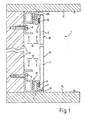
- a glass panel wall system 1 which consists of a glass plate 2, two to be connected to the building building profiles 3, 7 and two cooperating with these, attached to the glass plate 2 glass plate profiles 5, 9.
- the glass panel wall system 1 is sandwiched between a floor 15, a wall 16 and a ceiling 17.
- the glass plate 2 is fixed to the lower area via a lower profile pair 13 and in the upper area via an upper profile pair 14.
- the lower profile pair 13 consists of the on the bottom 15 resting and attached to the wall 16 by means of a screw 4 lower building profile 3 and the attached by means of an adhesive bond 6 to the glass plate 2 lower glass plate profile. 5
- the glass plate 2 rests on the lower profile pair 13 with the entire weight.
- the lower edge 11 of the glass plate 2 is supported on the lower glass plate profile 5, and this in turn on the lying on the floor 15 building profile.
- the lower building profile 3 does not rest on the floor 15, but is only attached to the wall. This could indeed be an optionally desired distance between the lower edge 11 of the plate 2 and the bottom 15 can be realized. In such a case, however, the lower building profile 3 would have to be correspondingly solid, so that the entire load of the glass plate can be introduced into the wall via this building profile.
- the upper profile pair 14 is used for the upper fixation and / or positioning of the glass plate 2. This is formed from the upper building profile 7 and the upper glass plate profile 9.
- the upper building profile 7 is disposed in the edge between the wall 16 and the ceiling 17 and fixed by means of the screw 8.
- the front side 18 of the glass plate 2 is in no way of elements of the building and glass plate profiles 3, 5; 7, 9 hidden. This results in the view of the mounted glass plates a completely freely designable visible surface over the entire front side 18. This is true for all glass plates 2, which are attached to the glass plate wall system 1 according to the invention.
- the preferred embodiment shown in FIG. 1 has a lower fixing and / or positioning means 19 between the building profile 3 and the glass panel profile 5.
- a corresponding contour is formed on both profiles 3, 5.
- the upper profile pair 14 is connected to each other by means of an upper fixing and / or positioning means 20.
- Both fixing and / or positioning means 19, 20 are formed in this embodiment as a form-locking connections, which interlock interlocking.
- the lower fixing and / or positioning means 19 is characterized by two matching, wavy contours of the mutually associated surfaces of the lower building profile 3 and the lower glass plate profile 5. So they work together in the function of a groove and an engaging web in multiple successively arranged execution.
- the individual details of the two fixing and / or positioning means 19, 20 are better removed from the figures 2 to 4.
- FIG. 2 shows a cross-section of the lower building profile 3.
- grooves and webs 21, 22 are arranged adjacent to one another. They engage in the complementary contour of the leg 26 of the lower glass plate profile 5, which is shown in FIG.
- grooves and webs 21, 22 are also formed on this leg 26.
- the shown, approximately rectangular contour of the legs and grooves 21, 22 with the rounded edges is only an example.
- the glass plate profile in FIG. 3 is designed such that it can be used both as a lower glass plate profile 5 and as an upper glass plate profile 9 glass plate profile.
- When used as the upper glass plate profile 9 engages the Web 24 in the groove 23 of the upper building profile 7 a. Both are each a part of the two connecting elements 27, 28, each having a receptacle for an associated web of the other profile.
- the groove 23 of the upper building profile 7 additionally has a taper 29, into which the web 24 engages in a predominantly sealing manner touching or at least almost touching.
- the glass panel wall system has a drainage means 31.
- this is realized by a bore 25 mounted in the bore and a channel extending parallel to the ground.
- a downwardly directed channel is also shown as drainage means 31 in leg 24.
- the schematic arrangement of the individual elements of the glass plate wall system 1 is shown in exploded exploded view. These are the glass plate 2, the lower and the upper building profile 3, 7, the lower and the upper glass plate profile 5, 9 and the side panel 32nd
Landscapes
- Engineering & Computer Science (AREA)
- Architecture (AREA)
- Civil Engineering (AREA)
- Structural Engineering (AREA)
- Chemical & Material Sciences (AREA)
- Ceramic Engineering (AREA)
- Load-Bearing And Curtain Walls (AREA)
- Securing Of Glass Panes Or The Like (AREA)
Applications Claiming Priority (1)
| Application Number | Priority Date | Filing Date | Title |
|---|---|---|---|
| DE102005010823A DE102005010823A1 (de) | 2005-03-07 | 2005-03-07 | Glasplatten-Wandbausystem |
Publications (2)
| Publication Number | Publication Date |
|---|---|
| EP1710363A1 true EP1710363A1 (fr) | 2006-10-11 |
| EP1710363B1 EP1710363B1 (fr) | 2011-12-07 |
Family
ID=36645568
Family Applications (1)
| Application Number | Title | Priority Date | Filing Date |
|---|---|---|---|
| EP06004454A Expired - Lifetime EP1710363B1 (fr) | 2005-03-07 | 2006-03-06 | Système de mur avec panneaux de verre |
Country Status (3)
| Country | Link |
|---|---|
| EP (1) | EP1710363B1 (fr) |
| AT (1) | ATE536447T1 (fr) |
| DE (1) | DE102005010823A1 (fr) |
Cited By (3)
| Publication number | Priority date | Publication date | Assignee | Title |
|---|---|---|---|---|
| CN113356411A (zh) * | 2021-06-22 | 2021-09-07 | 上海齐越建筑设计有限公司 | 一种可拆卸的造景帷幕墙 |
| EP4155475A1 (fr) | 2021-09-23 | 2023-03-29 | Jansen Building Products nv | Système et procédé de montage d'un mur |
| WO2025237955A1 (fr) | 2024-05-14 | 2025-11-20 | Jansen Prefab Nv | Système et procédé de montage d'une paroi |
Families Citing this family (5)
| Publication number | Priority date | Publication date | Assignee | Title |
|---|---|---|---|---|
| AT503532B1 (de) * | 2006-05-12 | 2013-11-15 | Bene Ag | Trennwand |
| DE102006054707A1 (de) | 2006-11-18 | 2008-05-21 | Martin Reuter | Brandschutzverglasung |
| DE202014104236U1 (de) * | 2014-09-08 | 2014-10-20 | Paul-Jean Munch | Einrichtung für die Körperhygiene |
| DE202014104235U1 (de) | 2014-09-08 | 2014-10-14 | Paul-Jean Munch | Als plattenförmiges Element ausgebildete Wandverkleidung |
| DE202016100794U1 (de) | 2016-01-08 | 2016-03-17 | Paul-Jean Munch | Befestigungsvorrichtung für ein Vorsatzelement |
Citations (8)
| Publication number | Priority date | Publication date | Assignee | Title |
|---|---|---|---|---|
| US4338753A (en) * | 1979-05-14 | 1982-07-13 | Hef Technische Entwicklung Gmbh & Co. Kg | Arrangement for connecting two profile members, particularly channel members for metal windows |
| US5152113A (en) | 1990-01-31 | 1992-10-06 | Guddas Juergen | Room partition |
| US5155958A (en) | 1991-10-17 | 1992-10-20 | Huff James C | Fastening and support system for architectural panels |
| SE510762C2 (sv) | 1995-08-14 | 1999-06-21 | Aqua Safety Wall Ab | Glasväggar i våtrum |
| US6170214B1 (en) * | 1998-06-09 | 2001-01-09 | Kenneth Treister | Cladding system |
| DE19958372C1 (de) * | 1999-12-06 | 2001-01-25 | Ver Glaswerke Gmbh | Verbundglasscheibe für eine Glaskonstruktion |
| EP1147981A2 (fr) * | 2000-04-19 | 2001-10-24 | GLASWERKE ARNOLD GmbH & Co. KG | Vitrage composite |
| GB2387856A (en) * | 2002-04-23 | 2003-10-29 | Lee Arnold Roth | Primary elongate frame member for partitioning system |
-
2005
- 2005-03-07 DE DE102005010823A patent/DE102005010823A1/de not_active Withdrawn
-
2006
- 2006-03-06 AT AT06004454T patent/ATE536447T1/de active
- 2006-03-06 EP EP06004454A patent/EP1710363B1/fr not_active Expired - Lifetime
Patent Citations (8)
| Publication number | Priority date | Publication date | Assignee | Title |
|---|---|---|---|---|
| US4338753A (en) * | 1979-05-14 | 1982-07-13 | Hef Technische Entwicklung Gmbh & Co. Kg | Arrangement for connecting two profile members, particularly channel members for metal windows |
| US5152113A (en) | 1990-01-31 | 1992-10-06 | Guddas Juergen | Room partition |
| US5155958A (en) | 1991-10-17 | 1992-10-20 | Huff James C | Fastening and support system for architectural panels |
| SE510762C2 (sv) | 1995-08-14 | 1999-06-21 | Aqua Safety Wall Ab | Glasväggar i våtrum |
| US6170214B1 (en) * | 1998-06-09 | 2001-01-09 | Kenneth Treister | Cladding system |
| DE19958372C1 (de) * | 1999-12-06 | 2001-01-25 | Ver Glaswerke Gmbh | Verbundglasscheibe für eine Glaskonstruktion |
| EP1147981A2 (fr) * | 2000-04-19 | 2001-10-24 | GLASWERKE ARNOLD GmbH & Co. KG | Vitrage composite |
| GB2387856A (en) * | 2002-04-23 | 2003-10-29 | Lee Arnold Roth | Primary elongate frame member for partitioning system |
Cited By (5)
| Publication number | Priority date | Publication date | Assignee | Title |
|---|---|---|---|---|
| CN113356411A (zh) * | 2021-06-22 | 2021-09-07 | 上海齐越建筑设计有限公司 | 一种可拆卸的造景帷幕墙 |
| EP4155475A1 (fr) | 2021-09-23 | 2023-03-29 | Jansen Building Products nv | Système et procédé de montage d'un mur |
| BE1029782A1 (nl) | 2021-09-23 | 2023-04-17 | Jansen Building Products Nv | Systeem en werkwijze voor montage van een wand |
| WO2025237955A1 (fr) | 2024-05-14 | 2025-11-20 | Jansen Prefab Nv | Système et procédé de montage d'une paroi |
| BE1032608A1 (nl) | 2024-05-14 | 2025-12-08 | Jansen Prefab Nv | Systeem en werkwijze voor montage van een wand |
Also Published As
| Publication number | Publication date |
|---|---|
| DE102005010823A1 (de) | 2006-09-14 |
| EP1710363B1 (fr) | 2011-12-07 |
| ATE536447T1 (de) | 2011-12-15 |
Similar Documents
| Publication | Publication Date | Title |
|---|---|---|
| EP2063047B1 (fr) | Système de rails profilés | |
| DE2059829A1 (de) | Struktursystem fuer den Zusammenbau von vorgefertigten Konstruktionen | |
| EP1710363B1 (fr) | Système de mur avec panneaux de verre | |
| EP0690951A1 (fr) | Profile mixte bois-aluminium | |
| EP1870529A1 (fr) | Mur/ensemble de coffre pour une construction de cadre | |
| AT511168B1 (de) | Trennwand | |
| AT517103B1 (de) | Befestigungssystem für Abdeckelemente | |
| WO2009006926A1 (fr) | CONCEPT DE PANNEAU DE PAROI À 45º | |
| DE19507765A1 (de) | Vorwandelement | |
| DE102013105774B4 (de) | Wandbefestigung für Glasscheibe | |
| DE102016104583A1 (de) | Profilsystem für Flügelelemente von Fassaden | |
| EP0365773A1 (fr) | Cloison | |
| EP2294266B1 (fr) | Élément de cloison, de plafond ou de sol ainsi que ouvrage et kit de construction comprenant de tels éléments | |
| AT505747B1 (de) | Wandsystem | |
| AT398229B (de) | Schachteinrichtung mit einem nach unten offenen aufnahmeschacht zur aufnahme eines rolladens, einer jalousie oder dergleichen | |
| AT525231B1 (de) | Raffstorekasten und Verbindungsbeschlag zur Befestigung des Raffstores | |
| DE102004055558B4 (de) | Profilschiene und Traggestell mit Profilschienen für Sanitärinstallationen | |
| AT8075U1 (de) | Abschlussleiste | |
| EP2586928B1 (fr) | Support de plaque en particulier pour panneaux en verre | |
| DE102011015494B4 (de) | Befestigungsanordnung | |
| EP4390042B1 (fr) | Ensemble constitué d'un vantail de porte en verre et d'un joint de porte automatique | |
| DE29901547U1 (de) | Abdeckleiste für plattenförmige Bauelemente | |
| EP1990477B1 (fr) | Panneau de construction léger doté d'une baguette de profilé | |
| AT520870B1 (de) | Modulare Abdeckung für Lichtschächte, mit der Möglichkeit unterschiedliche Designs darzustellen | |
| EP1816280A2 (fr) | Ensemble de lamelles pour façades |
Legal Events
| Date | Code | Title | Description |
|---|---|---|---|
| PUAI | Public reference made under article 153(3) epc to a published international application that has entered the european phase |
Free format text: ORIGINAL CODE: 0009012 |
|
| AK | Designated contracting states |
Kind code of ref document: A1 Designated state(s): AT BE BG CH CY CZ DE DK EE ES FI FR GB GR HU IE IS IT LI LT LU LV MC NL PL PT RO SE SI SK TR |
|
| AX | Request for extension of the european patent |
Extension state: AL BA HR MK YU |
|
| 17P | Request for examination filed |
Effective date: 20061220 |
|
| 17Q | First examination report despatched |
Effective date: 20070125 |
|
| AKX | Designation fees paid |
Designated state(s): AT CH DE GB LI NL |
|
| GRAP | Despatch of communication of intention to grant a patent |
Free format text: ORIGINAL CODE: EPIDOSNIGR1 |
|
| GRAS | Grant fee paid |
Free format text: ORIGINAL CODE: EPIDOSNIGR3 |
|
| RIN1 | Information on inventor provided before grant (corrected) |
Inventor name: KOLLETH, ROBERT |
|
| GRAA | (expected) grant |
Free format text: ORIGINAL CODE: 0009210 |
|
| AK | Designated contracting states |
Kind code of ref document: B1 Designated state(s): AT CH DE GB LI NL |
|
| REG | Reference to a national code |
Ref country code: GB Ref legal event code: FG4D Free format text: NOT ENGLISH |
|
| REG | Reference to a national code |
Ref country code: CH Ref legal event code: EP |
|
| REG | Reference to a national code |
Ref country code: DE Ref legal event code: R096 Ref document number: 502006010674 Country of ref document: DE Effective date: 20120216 |
|
| REG | Reference to a national code |
Ref country code: NL Ref legal event code: VDEP Effective date: 20111207 |
|
| PG25 | Lapsed in a contracting state [announced via postgrant information from national office to epo] |
Ref country code: NL Free format text: LAPSE BECAUSE OF FAILURE TO SUBMIT A TRANSLATION OF THE DESCRIPTION OR TO PAY THE FEE WITHIN THE PRESCRIBED TIME-LIMIT Effective date: 20111207 |
|
| PLBE | No opposition filed within time limit |
Free format text: ORIGINAL CODE: 0009261 |
|
| STAA | Information on the status of an ep patent application or granted ep patent |
Free format text: STATUS: NO OPPOSITION FILED WITHIN TIME LIMIT |
|
| REG | Reference to a national code |
Ref country code: CH Ref legal event code: PL |
|
| 26N | No opposition filed |
Effective date: 20120910 |
|
| GBPC | Gb: european patent ceased through non-payment of renewal fee |
Effective date: 20120307 |
|
| REG | Reference to a national code |
Ref country code: DE Ref legal event code: R097 Ref document number: 502006010674 Country of ref document: DE Effective date: 20120910 |
|
| PG25 | Lapsed in a contracting state [announced via postgrant information from national office to epo] |
Ref country code: LI Free format text: LAPSE BECAUSE OF NON-PAYMENT OF DUE FEES Effective date: 20120331 Ref country code: GB Free format text: LAPSE BECAUSE OF NON-PAYMENT OF DUE FEES Effective date: 20120307 Ref country code: CH Free format text: LAPSE BECAUSE OF NON-PAYMENT OF DUE FEES Effective date: 20120331 |
|
| PGFP | Annual fee paid to national office [announced via postgrant information from national office to epo] |
Ref country code: AT Payment date: 20170314 Year of fee payment: 12 |
|
| REG | Reference to a national code |
Ref country code: AT Ref legal event code: MM01 Ref document number: 536447 Country of ref document: AT Kind code of ref document: T Effective date: 20180306 |
|
| PG25 | Lapsed in a contracting state [announced via postgrant information from national office to epo] |
Ref country code: AT Free format text: LAPSE BECAUSE OF NON-PAYMENT OF DUE FEES Effective date: 20180306 |
|
| PGFP | Annual fee paid to national office [announced via postgrant information from national office to epo] |
Ref country code: DE Payment date: 20230320 Year of fee payment: 18 |
|
| REG | Reference to a national code |
Ref country code: DE Ref legal event code: R119 Ref document number: 502006010674 Country of ref document: DE |
|
| PG25 | Lapsed in a contracting state [announced via postgrant information from national office to epo] |
Ref country code: DE Free format text: LAPSE BECAUSE OF NON-PAYMENT OF DUE FEES Effective date: 20241001 |
|
| PG25 | Lapsed in a contracting state [announced via postgrant information from national office to epo] |
Ref country code: DE Free format text: LAPSE BECAUSE OF NON-PAYMENT OF DUE FEES Effective date: 20241001 |