EP1710619A1 - Dispositif d'eclairage et visualisateur d'images bidimensionnelles - Google Patents
Dispositif d'eclairage et visualisateur d'images bidimensionnelles Download PDFInfo
- Publication number
- EP1710619A1 EP1710619A1 EP05704112A EP05704112A EP1710619A1 EP 1710619 A1 EP1710619 A1 EP 1710619A1 EP 05704112 A EP05704112 A EP 05704112A EP 05704112 A EP05704112 A EP 05704112A EP 1710619 A1 EP1710619 A1 EP 1710619A1
- Authority
- EP
- European Patent Office
- Prior art keywords
- light source
- light
- lights
- light sources
- emitted
- Prior art date
- Legal status (The legal status is an assumption and is not a legal conclusion. Google has not performed a legal analysis and makes no representation as to the accuracy of the status listed.)
- Granted
Links
Images





Classifications
-
- G—PHYSICS
- G03—PHOTOGRAPHY; CINEMATOGRAPHY; ANALOGOUS TECHNIQUES USING WAVES OTHER THAN OPTICAL WAVES; ELECTROGRAPHY; HOLOGRAPHY
- G03B—APPARATUS OR ARRANGEMENTS FOR TAKING PHOTOGRAPHS OR FOR PROJECTING OR VIEWING THEM; APPARATUS OR ARRANGEMENTS EMPLOYING ANALOGOUS TECHNIQUES USING WAVES OTHER THAN OPTICAL WAVES; ACCESSORIES THEREFOR
- G03B21/00—Projectors or projection-type viewers; Accessories therefor
-
- G—PHYSICS
- G02—OPTICS
- G02B—OPTICAL ELEMENTS, SYSTEMS OR APPARATUS
- G02B27/00—Optical systems or apparatus not provided for by any of the groups G02B1/00 - G02B26/00, G02B30/00
- G02B27/10—Beam splitting or combining systems
- G02B27/1006—Beam splitting or combining systems for splitting or combining different wavelengths
- G02B27/102—Beam splitting or combining systems for splitting or combining different wavelengths for generating a colour image from monochromatic image signal sources
- G02B27/1046—Beam splitting or combining systems for splitting or combining different wavelengths for generating a colour image from monochromatic image signal sources for use with transmissive spatial light modulators
- G02B27/1053—Beam splitting or combining systems for splitting or combining different wavelengths for generating a colour image from monochromatic image signal sources for use with transmissive spatial light modulators having a single light modulator for all colour channels
-
- G—PHYSICS
- G02—OPTICS
- G02B—OPTICAL ELEMENTS, SYSTEMS OR APPARATUS
- G02B27/00—Optical systems or apparatus not provided for by any of the groups G02B1/00 - G02B26/00, G02B30/00
- G02B27/10—Beam splitting or combining systems
- G02B27/1073—Beam splitting or combining systems characterized by manufacturing or alignment methods
-
- G—PHYSICS
- G02—OPTICS
- G02B—OPTICAL ELEMENTS, SYSTEMS OR APPARATUS
- G02B27/00—Optical systems or apparatus not provided for by any of the groups G02B1/00 - G02B26/00, G02B30/00
- G02B27/10—Beam splitting or combining systems
- G02B27/1086—Beam splitting or combining systems operating by diffraction only
- G02B27/1093—Beam splitting or combining systems operating by diffraction only for use with monochromatic radiation only, e.g. devices for splitting a single laser source
-
- G—PHYSICS
- G02—OPTICS
- G02B—OPTICAL ELEMENTS, SYSTEMS OR APPARATUS
- G02B27/00—Optical systems or apparatus not provided for by any of the groups G02B1/00 - G02B26/00, G02B30/00
- G02B27/10—Beam splitting or combining systems
- G02B27/14—Beam splitting or combining systems operating by reflection only
- G02B27/149—Beam splitting or combining systems operating by reflection only using crossed beamsplitting surfaces, e.g. cross-dichroic cubes or X-cubes
-
- G—PHYSICS
- G03—PHOTOGRAPHY; CINEMATOGRAPHY; ANALOGOUS TECHNIQUES USING WAVES OTHER THAN OPTICAL WAVES; ELECTROGRAPHY; HOLOGRAPHY
- G03B—APPARATUS OR ARRANGEMENTS FOR TAKING PHOTOGRAPHS OR FOR PROJECTING OR VIEWING THEM; APPARATUS OR ARRANGEMENTS EMPLOYING ANALOGOUS TECHNIQUES USING WAVES OTHER THAN OPTICAL WAVES; ACCESSORIES THEREFOR
- G03B21/00—Projectors or projection-type viewers; Accessories therefor
- G03B21/14—Details
- G03B21/20—Lamp housings
- G03B21/208—Homogenising, shaping of the illumination light
-
- G—PHYSICS
- G03—PHOTOGRAPHY; CINEMATOGRAPHY; ANALOGOUS TECHNIQUES USING WAVES OTHER THAN OPTICAL WAVES; ELECTROGRAPHY; HOLOGRAPHY
- G03B—APPARATUS OR ARRANGEMENTS FOR TAKING PHOTOGRAPHS OR FOR PROJECTING OR VIEWING THEM; APPARATUS OR ARRANGEMENTS EMPLOYING ANALOGOUS TECHNIQUES USING WAVES OTHER THAN OPTICAL WAVES; ACCESSORIES THEREFOR
- G03B33/00—Colour photography, other than mere exposure or projection of a colour film
- G03B33/10—Simultaneous recording or projection
- G03B33/12—Simultaneous recording or projection using beam-splitting or beam-combining systems, e.g. dichroic mirrors
-
- H—ELECTRICITY
- H04—ELECTRIC COMMUNICATION TECHNIQUE
- H04N—PICTORIAL COMMUNICATION, e.g. TELEVISION
- H04N5/00—Details of television systems
- H04N5/74—Projection arrangements for image reproduction, e.g. using eidophor
-
- H—ELECTRICITY
- H04—ELECTRIC COMMUNICATION TECHNIQUE
- H04N—PICTORIAL COMMUNICATION, e.g. TELEVISION
- H04N9/00—Details of colour television systems
- H04N9/12—Picture reproducers
- H04N9/31—Projection devices for colour picture display, e.g. using electronic spatial light modulators [ESLM]
- H04N9/3102—Projection devices for colour picture display, e.g. using electronic spatial light modulators [ESLM] using two-dimensional electronic spatial light modulators
- H04N9/3111—Projection devices for colour picture display, e.g. using electronic spatial light modulators [ESLM] using two-dimensional electronic spatial light modulators for displaying the colours sequentially, e.g. by using sequentially activated light sources
- H04N9/3114—Projection devices for colour picture display, e.g. using electronic spatial light modulators [ESLM] using two-dimensional electronic spatial light modulators for displaying the colours sequentially, e.g. by using sequentially activated light sources by using a sequential colour filter producing one colour at a time
-
- H—ELECTRICITY
- H04—ELECTRIC COMMUNICATION TECHNIQUE
- H04N—PICTORIAL COMMUNICATION, e.g. TELEVISION
- H04N9/00—Details of colour television systems
- H04N9/12—Picture reproducers
- H04N9/31—Projection devices for colour picture display, e.g. using electronic spatial light modulators [ESLM]
- H04N9/3129—Projection devices for colour picture display, e.g. using electronic spatial light modulators [ESLM] scanning a light beam on the display screen
-
- H—ELECTRICITY
- H04—ELECTRIC COMMUNICATION TECHNIQUE
- H04N—PICTORIAL COMMUNICATION, e.g. TELEVISION
- H04N9/00—Details of colour television systems
- H04N9/12—Picture reproducers
- H04N9/31—Projection devices for colour picture display, e.g. using electronic spatial light modulators [ESLM]
- H04N9/3141—Constructional details thereof
- H04N9/315—Modulator illumination systems
Definitions
- the present invention relates to a light source device and a two-dimensional image display device and, more particularly, to a light source device that realizes miniaturization of a two-dimensional image display device, and a compact two-dimensional image display device using the light source device.
- a two-dimensional image display device (laser display device) capable of representing bright colors has attracted attention.
- This device adopts three coherent light sources of red, green, and blue (e.g., laser light sources), and has a construction as shown in figure 13.
- reference numeral 600 denotes a two-dimensional image display device using conventional laser light sources.
- the two-dimensional image display device 600 comprises red, green, and blue laser light sources 601a, 601b, and 601c, beam expanders 602a, 602b, and 602c, light integrators 603a, 603b, and 603c, mirrors 604a and 604c, diffusion plates 606a, 606b, and 606c, diffusion plate wobbling means 605a, 605b, and 605c, spatial light modulation elements 607a, 607b, and 607c, field lenses 608a, 608b, and 608c, a dichroic prism 609, and a projection lens 610.
- lights emitted from the red, green, and blue laser light sources 601a, 601b, and 601c are expanded by the beam expanders 602a, 602b, and 602c, and pass through the light integrators 603a, 603b, and 603c, respectively.
- the optical paths of the red and blue lights that pass through the light integrators 603a and 603c are bent at 90° by the mirrors 604a and 604c, respectively, while the optical path of the green light that passes through the light integrator 603b is not bent, and the respective lights irradiate the spatial light modulation elements 607a, 607b, and 607c through the field lenses 608a, 608b, and 608c, and the diffusion plates 606a, 606b, and 606c, respectively.
- the lights emitted from the three kinds of laser light sources 601a, 601b, and 601c pass through the light integrators 603a, 603b, and 603c, respectively, whereby the illumination distributions on the spatial light modulation elements 607a, 607b, and 607c are made uniform.
- the lights which are individually modulated by the spatial light modulation elements 607a, 607b, and 607c are multiplexed by the dichroic prism 609 to be coaxial beams that propagate in the same optical path, and further, enlarged and projected by the projection lens 610 to be focused on the screen 61.
- the laser light interference is high, speckle noises are superposed on the image projected on the screen 61.
- the diffusion plates 606a, 606b, and 606c are wobbled by the diffusion plate wobbling means 605a, 605b, and 605c, respectively, whereby the speckle noises are temporally averaged.
- the conventional two-dimensional image display device 600 shown in figure 13 in order to expand the lights from the three kinds of laser light sources 601a ⁇ 601c and make the intensity distributions of the lights uniform, three beam expanders and three light integrators are needed. Further, in order to convert the lights from the three kinds of laser light sources into coaxial beams which are parallel to each other and propagate in the same optical path, a lot of lenses and mirrors must be disposed in the device. Consequently, the conventional two-dimensional image display device is undesirably increased in scale.
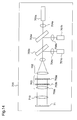
- the optical system of the two-dimensional image display device may be constituted such that, as shown in figure 14, initially lights emitted from laser light sources corresponding to three colors of red, green, and blue are mixed using dichroic mirrors, and thereafter, the mixed light is transmitted through a beam expander and a light integrator.
- reference numeral 700 denotes a conventional two-dimensional display device using laser light sources.
- the two-dimensional image display device 700 comprises red, green, and blue laser light sources 701a, 701b, and 701c, collimator lenses 704a, 704b, and 704c, first and second dichroic mirrors 705a and 705b, a beam expander 702, a light integrator 703, a projection lens 10, and a liquid crystal panel 71.
- the dichroic mirror is obtained by laminating multiple films on a glass substrate, and varies the transmissivity in accordance with the wavelength.
- the first dichroic mirror 705a reflects lights of wavelengths shorter than a threshold wavelength of about 580nm, and passes only lights having wavelengths longer than this threshold wavelength.
- the second dichroic mirror 705b reflects lights of wavelengths shorter than a threshold wavelength of about 490nm, and passes only lights having wavelengths longer than this threshold wavelength.
- the conventional two-dimensional image display device 700 using the laser light sources initially, lights emitted from the red, green, and blue laser light sources 701a, 701b, and 701c are collimated by the collimator lenses 704a, 704b, and 704c, respectively, and the collimated lights are converted to coaxial beams that are parallel to each other and propagate through the same optical path, by the first and second dichroic mirrors 705a and 705b, and thereafter, the coaxial beams are applied to the beam expander 702.
- the light beams incident on the beam expander 702 are expanded by the beam expander 702 and then pass through the light integrator 703.
- the light integrator 703 includes two fly-eye lenses 703a and 703b each comprising rectangle element lenses being two-dimensionally arrayed, and a collimator lens 703c.
- the lights incident on the respective element lenses of the first fly-eye lens 703 are focused on the two-dimensional spatial light modulation element by the second fly-eye lens 703b, whereby the light intensity distributions on the respective element lenses are multiplexed on the two-dimensional spatial light modulation element, and consequently, the light intensity distribution on the two-dimensional spatial light modulation element becomes uniform.
- the light that passes through the light integrator 703 and thereby has the uniform intensity distribution is focused on the liquid crystal panel 71 by the projection lens 710 (refer to Japanese Published Patent Application No.10-293268 (Patent Document 1)).
- the scale of the whole two-dimensional image display device can be further reduced in the construction shown in figure 14 wherein the lights emitted from the respective laser light sources 701a ⁇ 701c are multiplexed by the first and second dichroic mirrors 705a and 705b to convert them into coaxial beams, and then the coaxial beams are expanded, and thereafter, the light intensity distributions thereof are made uniform by the light integrator 703, relative to in the construction shown in figure 13 wherein the lights emitted from the respective laser light sources 601a ⁇ 601c are expanded by the beam expanders 602a ⁇ 602c, and then the light intensity distributions thereof are made uniform by the light integrators 603a ⁇ 603b, and thereafter, the light beams are multiplexed by the dichroic prism 609 to convert them into coaxial beams.
- the present invention is made to solve the above-described problems and has for its object to provide an ultracompact light source device that can be mounted on a compact device, and a compact two-dimensional image display device using the light source device.
- a light source device comprises at least two coherent light sources; and a diffraction part for diffracting light which is emitted from at least one of the coherent light sources so that the respective lights emitted from the at least two coherent light sources propagate through the same optical path.
- the respective lights emitted from the plural coherent light sources can be easily multiplexed in the diffraction part, resulting in an ultracompact light source device.
- the optical propagation paths of the respective lights emitted from the at least two coherent light sources overlap each other on the diffraction part.
- the light source device can be further miniaturized.
- the center axes of the optical propagation paths of the respective lights emitted from the at least two coherent light sources intersect at one point on the diffraction part.
- the light source device can be further miniaturized.
- the at least two coherent light sources are disposed on the same submount.
- heat radiation of three light sources can be carried out by heat radiation of the single submount, whereby heat radiation of the light sources in the light source device can be realized by the simple construction.
- the coherent light sources are a coherent light source that emits red light, a coherent light source that emits blue light, and a coherent light source that emits green light.
- a compact light source device that emits R, G, and B lights can be provided.
- the light emitted from at least one coherent light source among the coherent light sources passes through the diffraction part without being diffracted by the diffraction part.
- the production process of the diffraction part can be reduced, thereby providing the light source device at lower cost.
- the diffraction part comprises a single diffraction element, and the diffraction element diffracts the light emitted from at least one coherent light source so that the respective lights emitted from the at least two coherent light sources propagate through the same optical path.
- the diffraction part is downsized, whereby the light source device can be ultra-miniaturized.
- the diffraction element is further provided with a lens function.
- the respective lights emitted from the plural coherent light sources can irradiate the same planar region above the diffraction element.
- the diffraction part comprises a first diffraction element for receiving at least two lights, and diffracting at least one of the received lights so that the received at least two lights propagate through the same optical path; and a second diffraction element for diffracting the light emitted from at least one coherent light source among the at least two coherent light sources so that the center axes of the optical propagation paths of the lights emitted from the respective coherent light sources intersect at one point on the first diffraction element.
- the second diffraction element is further provided with a lens function, and the second diffraction element condenses the respective lights emitted from the at least two coherent light sources so that the respective lights diffracted by the second diffraction element irradiate the same region of the first diffraction element.
- the respective lights emitted from the plural coherent light sources can irradiate the same region of the first diffraction element that is disposed above the second diffraction element.
- the diffraction element is a volume hologram, and plural gratings are multiplexed on the volume hologram, which gratings receive the respective lights emitted from the at least two coherent light sources, and change the propagation directions of the respective lights.
- the diffraction element is regionally divided, and the respective lights that are diffracted in the divided regions of the diffraction element irradiate the same planar region.
- the diffraction element can be provided with the function of a light integrator, whereby the intensity distributions of the lights that irradiate the space can be made uniform.
- the diffraction element is regionally divided in a lattice pattern.
- the intensity distributions of the lights that irradiate the space can be made more uniform.
- a two-dimensional image display device comprises at least two coherent light sources; a diffraction part for diffracting light emitted from at least one coherent light source so that the respective lights emitted from the at least two coherent light sources propagate in the same optical path; and a two-dimensional spatial light modulation element for receiving the respective lights that are diffracted by the diffraction part to be coaxial beams, said element being provided in a space above the diffraction part.
- the two-dimensional image display according to the present invention further includes a control part for controlling the operations of the at least two coherent light sources, and the at least two coherent light sources are a coherent light source that emits red light, a coherent light source that emits green light, and a coherent light source that emits blue light, and the control part controls the three coherent light sources so that the coherent light sources are time-shared to sequentially emit lights.
- a light source device having plural coherent light sources is provided with a diffraction part that diffracts the respective lights emitted from the coherent light sources so that the lights propagate in the same optical path. Therefore, an optical system for multiplexing the respective lights emitted from the plural coherent light sources into coaxial beams can be downsized, thereby providing an ultracompact light source device.
- the light emitted from at least one coherent light source among the plural coherent light sources passes through the diffraction part without being diffracted by the diffraction part. Therefore, the number of gratings to be multiplexed on the diffraction part can be reduced, whereby the light source device can be constituted at low cost.
- the diffraction part is constituted by first and second diffraction gratings, and the second diffraction grating diffracts the lights from the plural coherent light sources so that these lights irradiate the same region of the first diffraction element, while the first diffraction grating diffracts the respective lights that pass through the second diffraction element so that these lights become coaxial beams. Therefore, it is possible to provide a compact light source device which can easily multiplex the lights from the plural light sources to be coaxial beams.
- the plural coherent light sources are disposed on the same submount. Therefore, heat radiation of the plural light sources can be carried out by heat radiation of the single submount, thereby facilitating heat radiation of the light source device.
- the diffraction part is regionally divided, and the divided regions of the diffraction part are respectively provided with plural gratings as well as functions of concave lenses. Therefore, the intensity distributions of the lights emitted from the diffraction part can be made uniform as well as the lights emitted from the plural coherent light sources can be easily converted into coaxial beams to be multiplexed. Further, the diffraction part having the light integrator that makes the intensity distributions of the lights emitted from the diffraction part uniform is more compact and can be fabricated using cheaper materials as compared with the conventional lens array, whereby the light source device can be realized at lower cost.
- the light source device is miniaturized using the diffraction element, whereby the two-dimensional image display device can be miniaturized.
- the two-dimensional image display device of the present invention since the diffraction part of the light source device also has the function of a light integrator, the intensity distributions of the lights emitted from the light source device become uniform without the necessity of using fly array lenses that are conventionally needed for making the light intensity distributions uniform, whereby the two-dimensional image display device in which the intensity distributions of the lights from the light sources are uniform can be more miniaturized, and further, the number of constituents of the two-dimensional image display device can be reduced. As the result, the two-dimensional image display device having the uniform intensity distributions of the lights from the light sources can be easily assembled at low cost.
- coaxial beams means lights that propagate in the same optical path
- light axis means a center axis of a light propagation path.
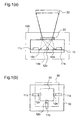
- Figure 1 is a diagram illustrating the construction of the light source device according to the first embodiment, wherein figure 1(a) is a side view and figure 1(b) is a plan view.
- reference numeral 100 denotes a light source device according to the first embodiment, and the light source device 100 is used as a light source for a two-dimensional image display device.
- the light source device 100 includes coherent light sources, i.e., three semiconductor lasers 11a ⁇ 11c emitting red light, blue light, and green light (hereinafter referred to simply as "laser light sources”), and a submount 10, such as a silicon substrate, on which the laser light sources 11a ⁇ 11c are directly mounted.
- coherent light sources i.e., three semiconductor lasers 11a ⁇ 11c emitting red light, blue light, and green light
- submount 10 such as a silicon substrate
- the light source device 100 includes a diffraction unit 20 which is disposed above the submount 10, and diffracts light beams emitted from at least one coherent light source, in this first embodiment, light beams emitted from the two laser light sources 11a, 11b, and 11c, so that all the light beams emitted from the three coherent light sources become coaxial beams; and prisms 12a, 12b, and 12c which are disposed on the submount 10, and reflect the light beams emitted from the three laser light sources 11a, 11b, and 11c so that the light beams emitted from the laser light sources 11a, 11b, and 11c irradiate the same region of the diffraction unit 20.
- a spatial light modulation element 30 for spatially modulating the amplitudes of the respective lights which are converted to the coaxial beams by the diffraction unit 20 is disposed above the diffraction part 20.
- the respective laser light sources 11a ⁇ 11c are surface-emitting lasers, and the red and green laser light sources 11a and 11b are disposed on a single straight line while the blue laser light source 11b is disposed on a straight line that is perpendicular to the above-mentioned straight line.
- the reflection angles of the reflection surfaces of the prisms 12a, 12b, and 12c are set so that the light axes of the emitted lights from the laser light sources 11a, 11b, and 11c, which are reflected at the reflection surfaces, and the light axis of the emitted light from the laser light source 11b intersect at one point on the diffraction unit 20.
- the diffraction unit 20 comprises a single volume hologram.
- a plurality of gratings for diffracting the lights emitted from the respective laser light sources 11a ⁇ 11c to convert these lights into coaxial beams are multiply-formed in the volume hologram.
- the volume hologram of the first embodiment also has a lens function for condensing the respective lights that pass through the diffraction unit 20 so that the respective lights irradiate the same region of the spatial light modulation element 30 disposed above the diffraction part 20.
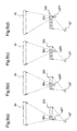
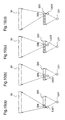
- Figure 2 is a diagram illustrating a method for fabricating the volume hologram according to the first embodiment, wherein figure 2(a) shows a method of forming a grating for the light emitted from the green light laser source 11c, figure 2(b) shows a method of forming a grating for the light emitted from the blue light laser source 11b, and figure 2(c) shows a method of forming a grating for the light emitted from the red light laser source 11a.
- a light source Lg1 and a light source Lg2 which have the same wavelength as that of the green light laser source 11c are used for fabrication of a grating corresponding to the light emitted from the green light laser source 11c.
- the light sources Lg1 and Lg2 emit laser lights which are emitted from the same light source and divided.
- light emitted from a single laser source is introduced into an optical fiber, and further, the fiber is divided into two fibers by a fiber coupler, and the emission facets of the two fibers are disposed in the positions of the light sources Lg1 and Lg2, respectively.
- the light source Lg1 is disposed so that its optical position with respect to the volume hologram 20 matches the position of the laser light source 11c shown in figures 1(a) and 1(b), and the light source Lg2 is disposed in the center of projection that projects the light emitting surface of the diffraction part 20 onto the entire light receiving surface of the spatial light modulation element 30.
- the spatial light modulation electrode 30 is positioned directly above the diffraction part 20
- the light source Lg2 is disposed on a straight line that is perpendicular to the light emission surface of the diffraction part 20 (refer to figure 2(a)).
- the volume hologram is subjected to interference exposure with the lights emitted from the light sources Lg1 and Lg2. Thereby, an interference pattern is recorded on the volume hologram to fabricate a Bragg grating that diffracts and condenses the light emitted from the laser light source 11c.
- a light source Lb1 and a light source Lb2 which have the same wavelength as that of the blue light laser source 11b are used for fabrication of a grating corresponding to the light emitted from the blue light laser source 11b.
- the light sources Lb1 and Lb2 emit laser lights which are emitted from the same light source and divided. For example, light emitted from a single laser source is introduced into an optical fiber, and further, the fiber is divided into two fibers by a fiber coupler, and the emission facets of the two fibers are disposed in the positions of the light sources Lb1 and Lb2, respectively.
- the light source Lb1 is disposed so that its optical position with respect to the volume hologram 20 matches the position of the laser light source 11b shown in figure 1, and the light source Lb2 is disposed in the same position as the light source Lg2 (refer to figure 2(b)). Then, the volume hologram is subjected to interference exposure with the lights emitted from the light sources Lb1 and Lb2. Thereby, an interference pattern is further recorded on the volume hologram to fabricate a Bragg grating that condenses the light emitted from the laser light source 11b.
- a light source Lr1 and a light source Lr2 which have the same wavelength as that of the red light laser source 11a are used for fabrication of a grating corresponding to the light emitted from the green light laser source 11a.
- the light sources Lr1 and Lr2 emit laser lights which are emitted from the same light source and divided. For example, light emitted from a single laser source is introduced into an optical fiber, and further, the fiber is divided into two fibers by a fiber coupler, and the emission facets of the two fibers are disposed in the positions of the light sources Lr1 and Lr2, respectively.
- the light source Lr1 is disposed so that its optical position with respect to the volume hologram 20 matches the position of the laser light source 11a shown in figure 1, and the light source Lr2 is disposed in the same position as the light source Lg2 (refer to figure 2(c)). Then, the volume hologram is subjected to interference exposure with the lights emitted from the light sources Lr1 and Lr2. Thereby, an interference pattern is further recorded on the volume hologram to fabricate a Bragg grating that condenses the light emitted from the laser light source 11a.
- the interference exposure of the volume hologram must be carried out three times so that the gratings corresponding to the respective emitted lights from the three laser sources are formed in the single volume hologram, and therefore, each interference exposure is carried out with such a light intensity that the photosensitive material constituting the volume hologram is completely exposed by the three times of exposures.
- the light source device 100 when lights are emitted from the laser light sources 11a ⁇ 11c of red, blue, and green lights which are disposed on the submount 10, the lights emitted from the three laser light sources 11a, 11b, and 11c are reflected by the prisms 12a, 12b, and 12c on the submount 10 so that the light axes of the respective emitted lights intersect at one point on the diffraction part 20.
- the red, blue, and green laser lights emitted from the respective laser light sources 11a, 11b, and 11c are multiplexed by the gratings corresponding to the respective lights in the diffraction part 20 so as to be coaxial beams as shown in figure 1, and the coaxial beams irradiate the same area of the spatial light modulation element 30, i.e., the light receiving surface. That is, the emitted lights from the red, blue, and green laser light sources 11a, 11b, and 11c, which are reflected by the prisms, are respectively diffracted and condensed when passing through the diffraction part 20. Thereby, the light emitted from the diffraction part 20, which is obtained by multiplexing the lights emitted from the three laser light sources, irradiates the light receiving surface that is a given area of the spatial light modulation element 30.
- the light source device is provided with the three laser light sources 11a ⁇ 11c, and the diffraction part 20 comprising a single volume hologram which multiplexes the lights emitted from the laser light sources 11a ⁇ 11c so that these lights become coaxial beams. Therefore, the optical system for converting the lights emitted from the three laser light sources into coaxial beams can be miniaturized, thereby realizing an ultracompact two-dimensional image display device that can be mounted on a compact apparatus such as a handy phone.
- heat radiation of the three light sources can be carried out by heat radiation of the single submount 10, whereby heat radiation of the light sources in the light source device can be facilitated.
- surface-emitting lasers are adopted as the three light sources 11a ⁇ 11c, and the blue light laser is disposed on a straight line that is perpendicular to a straight line connecting the green light laser and the red light laser.
- arrangement of the laser light sources is not restricted thereto.
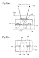
- FIGS 3(a) and 3(b) are a side view and a plan view illustrating a light source device 100a of such construction.
- the same reference numerals as those shown in figures 1(a) and 1(b) denote the same elements as those of the light source device 100.
- the number of prisms disposed on the submount 10 can be reduced, whereby the cost of the light source device 100 can be reduced.
- the semiconductor laser chips as the laser light sources are disposed on the same submount 10
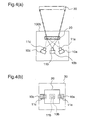
- the semiconductor laser chips as the laser light sources may be mounted on different submounts 10a ⁇ 10c, respectively, as in a light source device 100b shown in figures 4(a) and 4(b).
- Figures 4(a) and 4(b) are a side view and a plan view of the light source device 100b, wherein the same reference numerals as those in figure 1(a) and 1(b) denote the same elements as those of the light source device 100.
- the degree of freedom in layout of the three light sources is increased, thereby facilitating design of the light source device in a compact apparatus.
- the diffraction part 20 also has the function of a condenser lens, it is not necessary to condense the respective lights by the diffraction part 20 so long as the lights passing through the diffraction part 20 fall within the plane of the spatial light modulation element 30.
- the process steps for fabricating the volume hologram can be reduced, thereby providing the device at lower cost.
- the first embodiment is described for the case where three coherent light sources are used, at least two light sources suffice.
- three coherent light sources are used, at least two light sources suffice.
- blue-green or yellow light may be provided in addition to the red, blue, and green lights, thereby providing a light source device that can represent a wider range of bright colors.
- the light source device is used as a light source for a two-dimensional image display apparatus, and the spatial light modulation element 30 spatially varies the amplitude of the light emitted from the diffraction part 20.
- the light source device according to the first embodiment is not restricted to that for a two-dimensional image display device, and it may be used as a light source for a device, other than a two-dimensional image display device, in which the spatial light modulation element spatially varies the phase of the light from the diffraction part 20.
- the diffraction part comprises a single diffraction element
- the diffraction part comprises two diffraction elements.
- Figure 5 is a diagram illustrating the construction of the light source device according to the second embodiment, wherein figure 5(a) is a side view and figure 5(b) is a plan view.
- reference numeral 200 denotes a light source device according to the second embodiment.
- the light source device 200 is provided with a submount 10 such as a silicon substrate; three semiconductor laser light sources 21a ⁇ 21c which are disposed on the submount 10, and emit red light, blue light, and green light, respectively (hereinafter simply referred to as "laser light sources”); and a diffraction part 220 which is disposed above the submount 10 and diffracts the respective lights emitted from the three laser light sources 21a ⁇ 21c so that the respective lights become coaxial beams.
- a spatial light modulation element 30 for spatially varying the amplitudes of the lights that are converted to the coaxial beams by the diffraction part 220 is disposed above the diffraction part 220.
- the three laser light sources 21a ⁇ 21c are surface-emitting lasers that emit lights from upper surfaces of laser chips, and these lasers are disposed along a single straight line on the submount 10.
- the diffraction part 220 comprises two pieces of volume holograms (first and second volume holograms) 221 and 222.
- the second volume hologram 222 is disposed above the submount 10, and diffracts the respective lights emitted from the three laser light sources 21a ⁇ 21c so that the light axes of the respective emitted lights intersect at one point on the first volume hologram which is disposed above the second volume hologram 222, and further, condenses the respective emitted lights so as to irradiate the same area of the first volume hologram 221.
- the second volume hologram 222 is provided with a plurality of gratings according to the lights emitted from the respective laser light sources 21a ⁇ 21c, more specifically, a grating 222a for red light, a grating 222b for blue light, and a grating 222c for green light, so that the respective lights irradiate the same region of the first volume hologram 221.
- the first volume hologram 221 further diffracts the emitted lights from the respective light sources, which are diffracted by the second volume hologram 222, thereby converting the lights into coaxial beams.
- a plurality of gratings are multiply-formed on the first volume hologram 221, and the gratings diffract the emitted lights from the respective light sources, which pass through the second volume hologram 222, so that these lights are converted to coaxial beams.
- the intervals of the light sources 21a ⁇ 21c are reduced so that the lights emitted from the respective light sources overlap each other on the second volume hologram 222. Therefore, on the second volume hologram 222, the gratings 222a ⁇ 222c for red light, blue light, and green light are partially overlapped.
- Figure 6 is a diagram illustrating a method for fabricating the second volume hologram according to the second embodiment, wherein figure 6(a) shows a method of fabricating a grating for green light, figure 6(b) shows a method of fabricating a grating for blue light, and figure 6(c) shows a method of fabricating a grating for red light.
- figure 7 is a diagram illustrating a method for fabricating the first volume hologram according to the second embodiment, wherein figure 7(a) shows a method of fabricating a grating for green light, figure 7(b) shows a method of fabricating a grating for blue light, and figure 7(c) shows a method of fabricating a grating for red light.
- the second volume hologram 222 diffracts the lights emitted from the respective light sources 21a ⁇ 21c so that the light axes of these lights intersect at one point on the first volume hologram 221, and condenses the respective emitted lights so that these lights irradiate the same region of the first volume hologram 221.
- a light source Lg1 and a light source Lg2 having the same wavelength as that of the green light laser source 21c are used for fabrication of a grating corresponding to the light emitted from the green light laser source 21c.
- the light sources Lg1 and Lg2 emit laser lights which are emitted from the same light source and divided. For example, light emitted from a single laser light source is introduced into an optical fiber, and further, the optical fiber is divided into two fibers with a fiber coupler, and the emission facets of the two fibers are disposed in the positions of the Lg1 and Lg2.
- the light source Lg1 is disposed such that its optical position with respect to the volume hologram 222 matches the position of the laser light source 21c shown in figures 5(a) and 5(b), and the light source Lg2 is disposed in the center of projection when a region in the second volume hologram 222, which region is irradiated with the light emitted from the light source Lg1, is expanded and projected onto the entire surface of the first volume hologram 221 (refer to figure 6(a)). Then, the second volume hologram 222 is subjected to interference exposure by the lights emitted from the light sources Lg1 and Lg2.
- an interference pattern is recorded on the second volume hologram 222 to form a Bragg grating 222c for diffracting and condensing the light emitted from the laser light source 21c.
- a region other than the region to be exposed should be shielded with a light shielding mask having apertures corresponding to the divided regions.
- a light source Lb1 and a light source Lb2 having the same wavelength as that of the blue light laser source 21b are used for fabrication of a grating corresponding to the light emitted from the blue light laser source 21b.
- the light sources Lb1 and Lgb emit laser lights which are emitted from the same light source and divided. For example, light emitted from a single laser light source is introduced into an optical fiber, and further, the optical fiber is divided into two fibers with a fiber coupler, and the emission facets of the two fibers are disposed in the positions of the Lb1 and Lb2.
- the light source Lb1 is disposed such that its optical position with respect to the volume hologram 222 matches the position of the laser light source 21b shown in figures 5(a) and 5(b), and the light source Lb2 is disposed in the center of projection when a region in the second volume hologram 222, which region is irradiated with the light emitted from the light source Lb1, is expanded and projected onto the entire surface of the first volume hologram 221 (refer to figure 6(b)). Then, the second volume hologram 222 is subjected to interference exposure by the lights emitted from the light sources Lb1 and Lb2.
- an interference pattern is recorded on the second volume hologram 222 to form a Bragg grating 222b for diffracting and condensing the light emitted from the laser light source 21b.
- a region other than the region to be exposed should be shielded with a light shielding mask having apertures corresponding to the divided regions.
- a light source Lr1 and a light source Lr2 having the same wavelength as that of the green light laser source 21a are used for fabrication of a grating corresponding to the light emitted from the red light laser source 21a.
- the light sources Lr1 and Lr2 emit laser lights which are emitted from the same light source and then divided. For example, light emitted from a single laser light source is introduced into an optical fiber, and further, the optical fiber is divided into two fibers with a fiber coupler, and the emission facets of the two fibers are disposed in the positions of the Lr1 and Lr2.
- the light source Lr1 is disposed such that its optical position with respect to the volume hologram 222 matches the position of the laser light source 21a shown in figures 5(a) and 5(b), and the light source Lr2 is disposed in the center of projection when a region in the second volume hologram 222, which is irradiated with the light emitted from the light source Lr1, is expanded and projected onto the entire surface of the first volume hologram 221. Then, the second volume hologram 222 is subjected to interference exposure by the lights emitted from the light sources Lr1 and Lr2.
- an interference pattern is recorded on the second volume hologram 222 to form a Bragg grating 222a for diffracting and condensing the light emitted from the laser light source 21a.
- a region other than the region to be exposed should be shielded with a light shielding mask having apertures corresponding to the divided regions.
- the respective light sources are disposed closely so that the emitted lights from the light sources partially overlap each other on the second volume hologram 222, the adjacent Bragg grating 222a and Bragg grating 222b partially overlap, and the adjacent Bragg grating 222b and Bragg grating 222c partially overlap on the fabricated second volume hologram 222.
- the first volume hologram 221 diffracts and condenses the lights that are emitted from the respective light sources 21a ⁇ 21c and pass through the second volume hologram 222 so that these lights become coaxial beams.
- a lens Lc and a light source Lg2 and a light source Lg3 having the same wavelength as that of the green light laser source 21c are used for fabrication of a grating corresponding to the light emitted from the green light laser source 21c.
- the light sources Lg2 and Lg3 emit laser lights which are emitted from the same light source and then divided.
- light emitted from a single laser light source is introduced into an optical fiber, and further, the optical fiber is divided into two fibers with a fiber coupler, and the emission facets of the two fibers are disposed in the positions of the Lg2 and Lg3.
- the lens Lc condenses the divergent light from the light source Lg3 so that this light is incident on the first volume hologram as parallel light.
- the light source Lg2 is disposed in the center of projection when a region in the second volume hologram 222 where the grating 222c is formed is expanded and projected onto the entire surface of the first volume hologram 221. Then, the first volume hologram 221 is subjected to interference exposure by the lights emitted from the light sources Lg2 and Lg3. Thereby, an interference pattern is recorded on the first volume hologram 221 to form a Bragg grating for diffracting the light emitted from the laser light source 21c.
- the interference exposure of the first volume hologram 221 is carried out such that the light sources Lg1 and Lg2 shown in figure 7(a) are replaced with a light source Lb2 and a light source Lb3 having the same wavelength as that of the blue light laser source 21b as shown in figure 7(b), and further, the light sources Lg1 and Lg2 shown in figure 7(a) are replaced with a light source Lr2 and a light source Lr3 having the same wavelength as that of the red light laser source 21a as shown in figure 7(c).
- the first volume hologram 221 gratings for diffracting the light emitted from the blue light laser source 21b and the light emitted from the red light laser source 21a are formed over the Bragg grating corresponding to the green light laser source 21c.
- the light source Lb2 is disposed in the center of projection when a region in the second volume hologram 222 where the grating 222b is formed is expanded and projected over the entire surface of the first volume hologram 221, and the light source Lr2 is disposed in the center of projection when a region in the second volume hologram 222 where the grating 222a is formed is expanded and projected over the entire surface of the first volume hologram 221.
- each interference exposure should be carried out with such a light intensity that a photosensitive material constituting the volume hologram is completely exposed by the three times of exposures.
- laser lights are emitted from the red, blue, and green light laser sources 21a ⁇ 21c disposed on the submount 10, and the respective laser lights irradiate the second volume hologram 222 of the diffraction part 220.
- the respective lights emitted from the laser light sources 21a ⁇ 21c are respectively diffracted and condensed by the gratings 222a ⁇ 222c for red light, blue light, and green light when passing through the second voltage hologram 222. Thereby, the light axes of the respective lights intersect at one point on the first volume hologram 221, and the lights irradiate the same region of the first volume hologram 221.
- the respective lights which are diffracted and condensed by the second volume hologram 222 are diffracted and multiplexed so as to be coaxial beams that propagate in the same optical path as shown in figure 5(a) when passing through the first volume hologram 221, and irradiate the same region of the spatial light modulation element 30.
- the light source device is provided with the three laser light sources 21a ⁇ 21c, and the diffraction part 220 comprising a volume hologram, which multiplexes the lights emitted from the laser light sources 21a ⁇ 21c so that these lights become coaxial beams. Therefore, it is possible to realize an ultracompact two-dimensional image display device that can be mounted on a compact apparatus such as a handy phone, as in the first embodiment.
- the diffraction part 220 is constituted by the first and second volume holograms 221 and 222, the lights emitted from the three laser light sources are diffracted by the second volume hologram 222 so that the light axes of these emitted lights intersect at one point on the first volume hologram 221, and the three laser lights from the second volume hologram 222 are diffracted by the first volume hologram 221 so that these laser lights irradiate the same region of the spatial light modulation element 30.
- the light sources that emit lights in the vertical direction to the submount such as surface-emitting lasers, can be directly disposed on the submount 10.
- the construction of the light source device can be simplified, and the assembly thereof can be facilitated. This leads to a reduction in cost of the light source device.
- the three light sources 21a ⁇ 21c are disposed on the same submount 10, heat radiation of the three light sources can be carried out by radiating heat from the single submount 10, whereby heat radiation of the light sources in the light source device can be easily carried out.
- the second volume hologram 222 is constructed such that the boundary portions of the adjacent gratings 222a ⁇ 222c are slightly overlapped
- the second volume hologram 222 may be formed such that the greater parts of the gratings for the respective lights are overlapped. In this case, the scale of the device can be reduced.
- the second volume hologram 222 may be formed such that the gratings for the respective lights are not overlapped.
- the scale of the light source device is somewhat increased, heat radiation of the light sources can be efficiently carried out because an interval is secured between adjacent light sources disposed on the same submount 10.
- the second volume hologram 222 has a lens function, it is not necessary to condense the respective lights by the second volume hologram 222 as long as the irradiation areas of the lights that pass through the second volume hologram 222 falls within the plane of the first volume hologram 221. In this case, since only the different two gratings 222a and 222c for diffracting the lights emitted from the two laser light sources 21a and 21c are to be formed on the second volume hologram 222, the number of gratings to be multiply-formed onto the volume hologram can be reduced, thereby providing the device at lower cost.
- a light source device is constructed such that the diffraction part of the light source device according to the first embodiment has a function of a light integrator for making the light intensity distributions of the lights emitted from the respective laser light sources uniform.
- Figure 8 is a diagram illustrating the construction of the light source device according to the third embodiment, wherein figure 8(a) is a side view and figure 8(b) is a plan view.
- reference numeral 300 denotes a light source device according to the third embodiment.
- the light source device 300 includes laser light sources 11a, 11b, and 11c of red light, blue light, and green light, respectively, prisms 12a, 12b, and 12c for reflecting lights emitted from the red and green laser light sources 11a and 11c, a submount 10 for supporting these laser light sources and prisms, and a diffraction part 320 through which the lights emitted from the laser light sources 11a, 11b, and 11c and reflected by the prisms 12a, 12b, and 12c pass.
- the laser light sources 11a ⁇ 11c, the prisms 12a ⁇ 12c, and the submount 10 are identical to those of the first embodiment.
- the diffraction part 320 diffracts the incident lights and makes the light intensity distributions thereof uniform, and it is composed of a single volume hologram.
- the volume hologram 320 is divided into plural regions. In this third embodiment, it is divided into sixteen regions.
- the divided sixteen regions 32 are arranged four by four. Gratings are multiply-formed on the respective divided regions 32, which gratings diffract the lights that are emitted from the light sources 11a ⁇ 11c and applied to the respective regions so that the lights irradiate the entirety of the light irradiation surface of the spatial light modulation element 30.
- the respective regions of the volume hologram 320 have functions of concave lenses for expanding the divergence angles of the incident lights.
- the optical path of the light emitted from the blue light source 11b is mainly illustrated to simplify the figure, the lights emitted from the red and green light sources 11a and 11c are similarly applied to the divided regions of the diffraction part 320, and are diffracted and dispersed by the gratings that are multiply-formed on the respective divided regions, and further, irradiate the same region of the spatial light modulation element 30.
- Figure 9 is a diagram illustrating a method of fabricating gratings for diffracting light that is emitted from the green light laser source, on the volume hologram of the third embodiment
- figure 10 is a diagram illustrating a method of fabricating gratings for diffracting light that is emitted from the blue light laser source, on the volume hologram of the third embodiment
- figure 11 is a diagram illustrating a method of fabricating gratings for diffracting light that is emitted from the red light laser source, on the volume hologram of the third embodiment.
- a light source Lg1 and a light source Lg2 having the same wavelength as that of the green light laser source 11c are used for fabrication of gratings for diffracting the light emitted from the green light laser source 11c, as shown in figures 9(a) ⁇ 9(d).
- the light sources Lg1 and Lg2 emit laser lights which are emitted from the same light source and divided.
- light emitted from a single laser light source is introduced into an optical fiber, and further, the optical fiber is divided into two fibers with a fiber coupler, and the emission facets of the two fibers are disposed in the positions of the Lg1 and Lg2.
- the light source Lg1 is fixed at a position where the optical position with respect to the volume hologram 320 matches the position of the laser light source 11c shown in figures 8(a) and 8(b), and the position of the light source Lg2 is changed for each divided region 32.
- the light sources Lg1 and lg2 are disposed as shown in figures 9(a) ⁇ 9(d), and four times of interference exposures are carried out, whereby gratings 32c are formed in the four regions arranged in a line, among the divided sixteen regions of the volume hologram 320.
- the light source Lg2 is disposed in the center of projection when each region of the volume hologram 320 is expanded and projected onto the spatial light modulation element 30.
- the four times of interference exposures shown in figures 9(a) ⁇ 9(d) are performed for each line of the divided regions of the volume hologram 320, whereby gratings 32c for diffracting the emitted lights from the green light laser source 11c are formed on all the divided sixteen regions of the volume hologram 320.
- regions other than the regions to be exposed should be shielded with a light shielding mask having apertures corresponding to the divided regions.
- gratings for diffracting the light emitted from the blue light laser source 11b are fabricated as follows. That is, as shown in figures 10(a) ⁇ 10(d), interference exposure using a light source Lb1 and a light source Lb2 having the same wavelength as that of the blue light laser source 11b is carried out so that the light source Lb1 is fixed in a position where the optical position of the light source Lb1 with respect to the volume hologram 320 matches the position of the laser light source 11c, and the position of the light source Lb2 is varied for each divided region. At this time, the light sources Lb1 and Lb2 emit laser lights which are emitted from the same light source and divided.
- light emitted from a single laser light source is introduced into an optical fiber, and further, the optical fiber is divided into two fibers with a fiber coupler, and the emission facets of the two fibers are disposed in the positions of the Lb1 and Lb2.
- gratings 32b for diffracting the emitted light from the blue light laser source are formed in four regions arranged in a line among the divided sixteen regions 32 of the volume hologram 320 by four times of interference exposures shown in figures 10(a) ⁇ 10(d), and gratings 32b for diffracting the blue light are formed in all the divided sixteen regions 32 of the volume hologram 320 by performing the four times of interference exposures to the respective lines of the divided regions in the volume hologram 320. Also in this case, during the interference exposures for the respective divided regions, regions other than the regions to be exposed should be shielded.
- gratings for diffracting the light emitted from the red light laser source 11a are fabricated as follows. That is, as shown in figures 11(a) ⁇ 11(d), interference exposure using a light source Lr1 and a light source Lr2 having the same wavelength as that of the red light laser source 11a is carried out with the light source Lr1 being fixed in a position where the optical position of the light source Lr1 with respect to the volume hologram 320 matches the position of the laser light source 11a, and the position of the light source Lr2 being varied for each divided region. At this time, the light sources Lr1 and Lr2 emit laser lights which are emitted from the same light source and divided.
- light emitted from a single laser light source is introduced into an optical fiber, and further, the optical fiber is divided into two fibers with a fiber coupler, and the emission facets of the two fibers are disposed in the positions of the Lr1 and Lr2.
- gratings 32a for diffracting the emitted light from the red light laser source are formed in four regions arranged in a line among the divided sixteen regions 32 of the volume hologram 320, by four times of interference exposures shown in figures 11(a) ⁇ 11(d), and gratings 32a for diffracting the red light are formed in all the divided sixteen regions 32 of the volume hologram 320 by performing the four times of interference exposures to the respective lines of the divided regions. Also in this case, during the interference exposures for the respective divided regions, regions other than the regions to be exposed should be shielded.
- the emitted lights from the laser light sources 11a ⁇ 11c are reflected by the prisms 12a, 12b, and 12c disposed on the submount 10, and these reflected lights irradiate the diffraction part 320.
- the optical axes of the respective lights emitted from the laser light sources 11a ⁇ 11c are matched on the diffraction part 320, and the respective lights irradiate the same region of the diffraction part 320.
- the optical axes of the red, blue, and green lights that pass the respective divided regions 32 of the diffraction part 320 are matched in the respective regions 32, and these lights are diffracted and dispersed so as to irradiate the same region, i.e., the entire surface of the spatial light modulation element 30.
- the spatial light modulation element 30 is irradiated with light of uniform light intensity distribution, which is obtained by multiplexing the laser lights of the respective colors.
- the diffraction part 320 is regionally divided two-dimensionally, and the gratings for diffracting and dispersing the emitted lights from the respective light sources are multiply-formed on the respective divided regions of the diffraction part 320 so that the lights from the respective light sources, which pass through the respective regions, become coaxial beams, and irradiate the entire surface of the light irradiation region of the spatial light modulation element 30. Therefore, it is possible to provide an ultracompact light source device that can miniaturize the optical system for converting the emitted lights from the three laser light sources into coaxial beams, and that can make the intensity distributions of the lights from the respective light sources uniform on the spatial light modulation element 30.
- a volume hologram can be fabricated utilizing a compact and inexpensive photosensitive material (polymer). Therefore, when the diffraction part 320 comprising a volume hologram also has the function of a light integrator as described for this third embodiment, the cost of the device can be reduced.
- the diffraction part 320 comprises a single volume hologram
- the diffraction part may comprise two volume holograms as described for the second embodiment.
- the first volume hologram 221 shown in figure 5 is regionally divided as described for the third embodiment, whereby the intensity distributions of the lights from the respective light sources on the spatial light modulation element 30 can be made uniform as described for the third embodiment.
- the regional division of the diffraction part is not restricted to the division into 16 regions, and it is possible to perform division into 64 regions or 128 regions, or more regions. Further, it is possible to perform the regional division of the diffraction part so that the numbers of divided regions arranged in the vertical and horizontal directions are varied according to the planar shape of the spatial light modulation element.
- Figure 12 is a diagram illustrating the construction of the two-dimensional image display device according to the fourth embodiment.
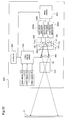
- reference numeral 500 denotes a two-dimensional image display device according to the fourth embodiment, and this two-dimensional image display device 500 comprises a light source device 300 including laser light sources 11a, 11b, and 11c corresponding to red light, blue light, and green light; laser driving units 550a ⁇ 550c for red light, blue light, and green light, which drive the respective laser light sources in the light source device 300; a laser switching unit 540 for selecting one of the respective laser driving units 550a ⁇ 550c; a video signal switching unit 530 for selecting any of a red video signal, a blue video signal, and a green video signal which are supplied from the outside, and outputting the selected video signal to a spatial light modulation element 30; a control unit 520 for outputting a control signal to successively display the R, G, and B images, thereby controlling the laser switching unit 540 and the video signal switching unit 530; a field lens 560 for converting the respective laser lights emitted from the light source device 300 into a condensed light flux near
- the video signal switching unit 530 successively selects the inputted red video signal, blue video signal, and green video signal according to the control signal supplied from the control unit 520, and outputs the signals to the spatial light modulation element 30.
- the laser switching unit 540 drives the red light, blue light, and green light laser driving units 550a ⁇ 550c according to the control signal from the control unit 520 to successively activate the red color, blue color, and green color laser light sources 11a ⁇ 11c.
- the spatial light modulation element 30 Thereby, light emissions in the respective color laser sources and formations of images of the respective colors by the spatial light modulation element 30 are synchronously carried out.
- the red light laser source 11a emits light
- the red video signal is supplied to the spatial light modulation element 30 and thereby modulation of the red light is carried out.
- the blue light laser source 11b emits light
- the blue video signal is supplied to the spatial light modulation element 30 and thereby modulation of the blue light is carried out.
- the green light laser source 11c the green video signal is supplied to the spatial light modulation element 30 and thereby modulation of the green light is carried out.
- the images formed by the modulations of the respective color lights by the spatial light modulation element 30 are projected on the screen 51 by the projection lens 510.
- the control unit 520 controls the light sources 11a ⁇ 11c so that each of these light sources emits light several times during picture display of one frame of a picture that is displayed at 30 frames per sec, whereby the pictures of the respective colors are inseparable when observed with human eyes, and therefore, the user can observe a full-color natural moving picture.
- the light source device of the two-dimensional image display device 500 comprises the three laser light sources 11a ⁇ 11c, and the diffraction part 320 comprising a volume hologram, for multiplexing the lights emitted from the laser light sources 11a ⁇ 11c so that these lights become coaxial beams. Therefore, the optical system for converting the emitted lights from the three laser light sources into coaxial beams can be miniaturized, whereby the two-dimensional image display device can be miniaturized.
- the light source device 300 since the light source device 300 also functions as a light integrator, the intensity distribution of light outputted from the light source device can be made uniform without using a light integrator comprising a fly-eye lens which is conventionally needed for making the light intensity distribution uniform. Therefore, the two-dimensional image display device in which the intensity distributions of the lights emitted from the light sources can be further miniaturized, and further, the number of constituents of the two-dimensional image display device can be reduced, thereby realizing a two-dimensional image display device that is easy to assemble and is reduced in cost.
Landscapes
- Physics & Mathematics (AREA)
- General Physics & Mathematics (AREA)
- Optics & Photonics (AREA)
- Engineering & Computer Science (AREA)
- Multimedia (AREA)
- Signal Processing (AREA)
- Manufacturing & Machinery (AREA)
- Projection Apparatus (AREA)
- Holo Graphy (AREA)
- Diffracting Gratings Or Hologram Optical Elements (AREA)
Applications Claiming Priority (2)
| Application Number | Priority Date | Filing Date | Title |
|---|---|---|---|
| JP2004021639 | 2004-01-29 | ||
| PCT/JP2005/000975 WO2005073798A1 (fr) | 2004-01-29 | 2005-01-26 | Dispositif d’eclairage et visualisateur d’images bidimensionnelles |
Publications (3)
| Publication Number | Publication Date |
|---|---|
| EP1710619A1 true EP1710619A1 (fr) | 2006-10-11 |
| EP1710619A4 EP1710619A4 (fr) | 2010-01-06 |
| EP1710619B1 EP1710619B1 (fr) | 2018-07-04 |
Family
ID=34823804
Family Applications (1)
| Application Number | Title | Priority Date | Filing Date |
|---|---|---|---|
| EP05704112.1A Ceased EP1710619B1 (fr) | 2004-01-29 | 2005-01-26 | Dispositif d'eclairage et visualisateur d'images bidimensionnelles |
Country Status (6)
| Country | Link |
|---|---|
| US (2) | US20080225361A1 (fr) |
| EP (1) | EP1710619B1 (fr) |
| JP (1) | JP4077484B2 (fr) |
| KR (1) | KR101180140B1 (fr) |
| CN (1) | CN1914556B (fr) |
| WO (1) | WO2005073798A1 (fr) |
Cited By (5)
| Publication number | Priority date | Publication date | Assignee | Title |
|---|---|---|---|---|
| WO2007030214A1 (fr) * | 2005-09-06 | 2007-03-15 | Hewlett-Packard Development Company, L.P. | Système et procédé de couplage lumineux |
| DE102007034958A1 (de) * | 2007-04-30 | 2008-11-06 | Osram Opto Semiconductors Gmbh | Strahlenkombinator für ein mehrfarbiges Laserdisplay |
| DE102010012604A1 (de) * | 2010-03-24 | 2011-09-29 | Osram Opto Semiconductors Gmbh | Halbleiterlaserlichtquelle |
| DE102012103257A1 (de) * | 2012-04-16 | 2013-10-17 | Osram Opto Semiconductors Gmbh | Laserdiodenvorrichtung |
| US8897327B2 (en) | 2012-04-16 | 2014-11-25 | Osram Opto Semiconductors Gmbh | Laser diode devices |
Families Citing this family (88)
| Publication number | Priority date | Publication date | Assignee | Title |
|---|---|---|---|---|
| JPWO2006093134A1 (ja) * | 2005-03-01 | 2008-08-07 | 松下電器産業株式会社 | ディスプレイ装置用光源装置、ディスプレイ装置、及びディスプレイ装置の画像調整方法 |
| JP4784262B2 (ja) * | 2005-10-31 | 2011-10-05 | セイコーエプソン株式会社 | 照明装置及び画像表示装置 |
| GB0522968D0 (en) | 2005-11-11 | 2005-12-21 | Popovich Milan M | Holographic illumination device |
| GB0718706D0 (en) | 2007-09-25 | 2007-11-07 | Creative Physics Ltd | Method and apparatus for reducing laser speckle |
| US8477315B2 (en) * | 2007-02-09 | 2013-07-02 | Seiko Epson Corporation | Volume hologram, light source device, illumination device, monitor, and image display device |
| WO2008114502A1 (fr) * | 2007-03-19 | 2008-09-25 | Panasonic Corporation | Dispositif d'éclairage laser et dispositif d'affichage d'image |
| EP1975680A1 (fr) * | 2007-03-31 | 2008-10-01 | Sony Deutschland Gmbh | Dispositif d'éclairage et procédé pour éclairer une image de manière uniforme pour générer un micro-affichage |
| JP5315845B2 (ja) | 2008-08-07 | 2013-10-16 | 株式会社リコー | 照明装置及び投影型画像表示装置 |
| JP5262849B2 (ja) * | 2009-03-06 | 2013-08-14 | セイコーエプソン株式会社 | プロジェクター |
| JP5359483B2 (ja) | 2009-04-10 | 2013-12-04 | 住友電気工業株式会社 | 光合波器及びそれを用いた画像投影装置 |
| JP2010243987A (ja) * | 2009-04-10 | 2010-10-28 | Sumitomo Electric Ind Ltd | 光合波器及びそれを用いた画像投影装置 |
| US9335604B2 (en) | 2013-12-11 | 2016-05-10 | Milan Momcilo Popovich | Holographic waveguide display |
| US11726332B2 (en) | 2009-04-27 | 2023-08-15 | Digilens Inc. | Diffractive projection apparatus |
| WO2011042711A2 (fr) | 2009-10-09 | 2011-04-14 | Milan Momcilo Popovich | Dispositif d'affichage à diffraction éclairé par la tranche compact |
| US11204540B2 (en) | 2009-10-09 | 2021-12-21 | Digilens Inc. | Diffractive waveguide providing a retinal image |
| DE102010044875A1 (de) * | 2010-09-09 | 2012-03-15 | Limo Patentverwaltung Gmbh & Co. Kg | Beleuchtungsvorrichtung zur Erzeugung einer linienförmigen Intensitätsverteilung in einer Arbeitsebene |
| WO2012053167A1 (fr) * | 2010-10-19 | 2012-04-26 | パナソニック株式会社 | Multiplexeur optique et projecteur |
| JP6062141B2 (ja) * | 2010-11-26 | 2017-01-18 | 大日本印刷株式会社 | 面照明装置およびバックライト装置 |
| US9274349B2 (en) | 2011-04-07 | 2016-03-01 | Digilens Inc. | Laser despeckler based on angular diversity |
| JP5743077B2 (ja) * | 2011-04-22 | 2015-07-01 | 大日本印刷株式会社 | 投射型映像表示装置 |
| WO2016020630A2 (fr) | 2014-08-08 | 2016-02-11 | Milan Momcilo Popovich | Illuminateur laser en guide d'ondes comprenant un dispositif de déchatoiement |
| EP2995986B1 (fr) | 2011-08-24 | 2017-04-12 | Rockwell Collins, Inc. | Affichage de données |
| US10670876B2 (en) | 2011-08-24 | 2020-06-02 | Digilens Inc. | Waveguide laser illuminator incorporating a despeckler |
| WO2013102759A2 (fr) | 2012-01-06 | 2013-07-11 | Milan Momcilo Popovich | Capteur d'image à contact utilisant des réseaux de bragg commutables |
| JP5849728B2 (ja) | 2012-01-26 | 2016-02-03 | 株式会社Jvcケンウッド | 投射型表示装置 |
| JP5849727B2 (ja) | 2012-01-26 | 2016-02-03 | 株式会社Jvcケンウッド | 投射型表示装置 |
| JP5924578B2 (ja) * | 2012-03-30 | 2016-05-25 | 大日本印刷株式会社 | 照明装置、投射装置および投射型映像表示装置 |
| WO2013163347A1 (fr) | 2012-04-25 | 2013-10-31 | Rockwell Collins, Inc. | Affichage grand angle holographique |
| US9456744B2 (en) | 2012-05-11 | 2016-10-04 | Digilens, Inc. | Apparatus for eye tracking |
| US8773613B2 (en) | 2012-05-29 | 2014-07-08 | Ergophos, Llc | Liquid-crystal display with coherent illumination and reduced speckling |
| US8870382B2 (en) | 2012-05-29 | 2014-10-28 | Vladimir Yankov | Method of reducing speckles in liquid-crystal display with coherent illumination |
| US8861057B2 (en) | 2012-06-27 | 2014-10-14 | Ergophos, Llc | Speckle-reduced laser illumination device |
| US8854710B2 (en) | 2012-06-27 | 2014-10-07 | Ergophos, Llc | Method of laser illumination with reduced speckling |
| US9933684B2 (en) | 2012-11-16 | 2018-04-03 | Rockwell Collins, Inc. | Transparent waveguide display providing upper and lower fields of view having a specific light output aperture configuration |
| JP5534056B2 (ja) * | 2013-02-15 | 2014-06-25 | セイコーエプソン株式会社 | 照明装置、画像表示装置及びプロジェクタ |
| WO2014188149A1 (fr) | 2013-05-20 | 2014-11-27 | Milan Momcilo Popovich | Dispositif holographique de suivi d'un œil à guide d'onde |
| US9727772B2 (en) | 2013-07-31 | 2017-08-08 | Digilens, Inc. | Method and apparatus for contact image sensing |
| JP5915949B2 (ja) * | 2014-06-25 | 2016-05-11 | パナソニックIpマネジメント株式会社 | 投影システム |
| US10359736B2 (en) | 2014-08-08 | 2019-07-23 | Digilens Inc. | Method for holographic mastering and replication |
| US10241330B2 (en) | 2014-09-19 | 2019-03-26 | Digilens, Inc. | Method and apparatus for generating input images for holographic waveguide displays |
| EP3198192A1 (fr) | 2014-09-26 | 2017-08-02 | Milan Momcilo Popovich | Dispositif de poursuite optique à guide d'ondes holographique |
| WO2016080908A1 (fr) * | 2014-11-21 | 2016-05-26 | Heptagon Micro Optics Pte. Ltd. | Projection de motif optique |
| EP3245444B1 (fr) | 2015-01-12 | 2021-09-08 | DigiLens Inc. | Affichage à guide d'ondes isolé de l'environnement |
| WO2016113533A2 (fr) | 2015-01-12 | 2016-07-21 | Milan Momcilo Popovich | Afficheurs à champ lumineux et à guide d'ondes holographiques |
| WO2016116733A1 (fr) | 2015-01-20 | 2016-07-28 | Milan Momcilo Popovich | Lidar à guide d'ondes holographique |
| US9632226B2 (en) | 2015-02-12 | 2017-04-25 | Digilens Inc. | Waveguide grating device |
| WO2016146963A1 (fr) | 2015-03-16 | 2016-09-22 | Popovich, Milan, Momcilo | Dispositif de guide d'onde incorporant un conduit de lumière |
| US10591756B2 (en) | 2015-03-31 | 2020-03-17 | Digilens Inc. | Method and apparatus for contact image sensing |
| GB2542117B (en) * | 2015-09-04 | 2022-04-06 | Smidsy Ltd | Laser projection device |
| WO2017043531A1 (fr) * | 2015-09-07 | 2017-03-16 | 大日本印刷株式会社 | Dispositif d'éclairage |
| CN113759555B (zh) | 2015-10-05 | 2024-09-20 | 迪吉伦斯公司 | 波导显示器 |
| US10983340B2 (en) | 2016-02-04 | 2021-04-20 | Digilens Inc. | Holographic waveguide optical tracker |
| CN108700265B (zh) | 2016-02-24 | 2021-10-15 | 大日本印刷株式会社 | 照明装置 |
| WO2017145972A1 (fr) * | 2016-02-24 | 2017-08-31 | 大日本印刷株式会社 | Dispositif d'éclairage |
| JP6344463B2 (ja) * | 2016-02-24 | 2018-06-20 | 大日本印刷株式会社 | 照明装置 |
| JP6850424B2 (ja) * | 2016-02-24 | 2021-03-31 | 大日本印刷株式会社 | 光源装置及び照明装置 |
| WO2017162999A1 (fr) | 2016-03-24 | 2017-09-28 | Popovich Milan Momcilo | Procédé et appareil pour fournir un dispositif guide d'ondes holographique sélectif en polarisation |
| US10890707B2 (en) | 2016-04-11 | 2021-01-12 | Digilens Inc. | Holographic waveguide apparatus for structured light projection |
| JP6471840B2 (ja) | 2016-11-17 | 2019-02-20 | 大日本印刷株式会社 | 照明装置 |
| EP3548939A4 (fr) | 2016-12-02 | 2020-11-25 | DigiLens Inc. | Dispositif de guide d'ondes à éclairage de sortie uniforme |
| WO2018129398A1 (fr) | 2017-01-05 | 2018-07-12 | Digilens, Inc. | Dispositifs d'affichage tête haute vestimentaires |
| DE102017200709A1 (de) | 2017-01-18 | 2018-07-19 | Robert Bosch Gmbh | Optische Anordnung zur Strahlzusammenführung |
| US11732860B2 (en) | 2017-04-27 | 2023-08-22 | Dai Nippon Printing Co., Ltd. | Illumination device |
| EP3460585B1 (fr) * | 2017-09-25 | 2021-07-14 | Imec Vzw | Dispositif d'imagerie pour imagerie holographique en ligne d'un objet |
| US10942430B2 (en) | 2017-10-16 | 2021-03-09 | Digilens Inc. | Systems and methods for multiplying the image resolution of a pixelated display |
| US10914950B2 (en) | 2018-01-08 | 2021-02-09 | Digilens Inc. | Waveguide architectures and related methods of manufacturing |
| US10732569B2 (en) | 2018-01-08 | 2020-08-04 | Digilens Inc. | Systems and methods for high-throughput recording of holographic gratings in waveguide cells |
| US20190212588A1 (en) | 2018-01-08 | 2019-07-11 | Digilens, Inc. | Systems and Methods for Manufacturing Waveguide Cells |
| KR20250004154A (ko) | 2018-01-08 | 2025-01-07 | 디지렌즈 인코포레이티드. | 광 도파관의 제조 방법 |
| CN112088332B (zh) | 2018-03-16 | 2024-11-29 | 迪吉伦斯公司 | 包含双折射控制的全息波导及用于它们的制造的方法 |
| US10916448B2 (en) | 2018-07-05 | 2021-02-09 | Texas Instruments Incorporated | Method for creating a wettable surface for improved reliability in QFN packages |
| WO2020023779A1 (fr) | 2018-07-25 | 2020-01-30 | Digilens Inc. | Systèmes et procédés pour fabriquer une structure optique multicouches |
| US11109004B2 (en) | 2018-07-31 | 2021-08-31 | Texas Instruments Incorporated | Display with increased pixel count |
| US11131796B2 (en) * | 2018-09-10 | 2021-09-28 | Texas Instruments Incorporated | Optical display with spatial light modulator |
| WO2020149956A1 (fr) | 2019-01-14 | 2020-07-23 | Digilens Inc. | Affichage de guide d'ondes holographique avec couche de commande de lumière |
| US20200247017A1 (en) | 2019-02-05 | 2020-08-06 | Digilens Inc. | Methods for Compensating for Optical Surface Nonuniformity |
| CN113692544B (zh) | 2019-02-15 | 2025-04-22 | 迪吉伦斯公司 | 使用集成光栅提供全息波导显示的方法和装置 |
| US20220283377A1 (en) | 2019-02-15 | 2022-09-08 | Digilens Inc. | Wide Angle Waveguide Display |
| US20200292745A1 (en) | 2019-03-12 | 2020-09-17 | Digilens Inc. | Holographic Waveguide Backlight and Related Methods of Manufacturing |
| JP7398878B2 (ja) * | 2019-04-23 | 2023-12-15 | 株式会社小糸製作所 | 光学素子および光源装置 |
| CN114207492A (zh) | 2019-06-07 | 2022-03-18 | 迪吉伦斯公司 | 带透射光栅和反射光栅的波导及其生产方法 |
| US11681143B2 (en) | 2019-07-29 | 2023-06-20 | Digilens Inc. | Methods and apparatus for multiplying the image resolution and field-of-view of a pixelated display |
| KR102775783B1 (ko) | 2019-08-29 | 2025-02-28 | 디지렌즈 인코포레이티드. | 진공 격자 및 이의 제조 방법 |
| JP2024502255A (ja) | 2020-12-21 | 2024-01-18 | ディジレンズ インコーポレイテッド | 導波路ベースのディスプレイにおけるアイグロー抑制 |
| WO2022150841A1 (fr) | 2021-01-07 | 2022-07-14 | Digilens Inc. | Structures de réseau pour guides d'ondes de couleur |
| EP4288831A4 (fr) | 2021-03-05 | 2025-01-15 | Digilens Inc. | Structures périodiques évacuées et leurs procédés de fabrication |
| DE102022213136A1 (de) * | 2022-12-06 | 2024-06-06 | Robert Bosch Gesellschaft mit beschränkter Haftung | Strahlvereinigungsvorrichtung |
| JP2025147732A (ja) * | 2024-03-25 | 2025-10-07 | スタンレー電気株式会社 | 照明装置 |
Family Cites Families (23)
| Publication number | Priority date | Publication date | Assignee | Title |
|---|---|---|---|---|
| JP2570946B2 (ja) * | 1992-06-25 | 1997-01-16 | キヤノン株式会社 | カラー画像読取装置 |
| JPH10293268A (ja) | 1997-04-17 | 1998-11-04 | Sony Corp | レーザディスプレイ装置 |
| JPH10319873A (ja) * | 1997-05-15 | 1998-12-04 | Mitsubishi Electric Corp | 光源ユニットおよびこれを用いた表示装置、表示器、照明装置 |
| JP3778316B2 (ja) * | 1997-05-22 | 2006-05-24 | パイオニア株式会社 | 光ピックアップ装置 |
| JP3975514B2 (ja) * | 1997-08-15 | 2007-09-12 | ソニー株式会社 | レーザディスプレイ装置 |
| WO1999049358A1 (fr) * | 1998-03-26 | 1999-09-30 | Mitsubishi Denki Kabushiki Kaisha | Afficheur d'images et dispositif emettant de la lumiere |
| US6185016B1 (en) * | 1999-01-19 | 2001-02-06 | Digilens, Inc. | System for generating an image |
| JP2000242192A (ja) * | 1999-02-24 | 2000-09-08 | Sony Corp | 画像表示装置 |
| JP4270420B2 (ja) * | 1999-05-07 | 2009-06-03 | 大日本印刷株式会社 | 投影スクリーン |
| US6928035B2 (en) * | 2000-07-07 | 2005-08-09 | Matsushita Electric Industrial Co., Ltd. | Optical pick-up, optical disk apparatus and information processing apparatus |
| JP2002056706A (ja) * | 2000-08-07 | 2002-02-22 | Opt Design:Kk | 照明装置 |
| AU2002233917A1 (en) * | 2000-09-14 | 2002-05-06 | Jr. Jacob L. Kuykendall | Method and system using holographic methodologies for all-optical transmission and reception of high bandwidth signals |
| JP4646278B2 (ja) * | 2000-10-26 | 2011-03-09 | 株式会社リコー | 照明光学系及び投射装置 |
| JP4859311B2 (ja) * | 2001-09-17 | 2012-01-25 | 株式会社リコー | レーザ照明光学系、該光学系を用いた露光装置、レーザ加工機、及び投射装置 |
| KR100440958B1 (ko) * | 2001-10-12 | 2004-07-21 | 삼성전자주식회사 | 조명계 및 이를 채용한 프로젝터 |
| KR100403599B1 (ko) * | 2001-11-06 | 2003-10-30 | 삼성전자주식회사 | 조명계 및 이를 채용한 프로젝션 시스템 |
| JP2003270585A (ja) * | 2002-03-18 | 2003-09-25 | Ricoh Co Ltd | レーザ照明光学系及びそれを用いた露光装置、レーザ加工装置、投射装置 |
| JP2003295112A (ja) * | 2002-04-05 | 2003-10-15 | Canon Inc | 走査型画像表示光学系、走査型画像表示装置および画像表示システム |
| JP2003330109A (ja) * | 2002-05-09 | 2003-11-19 | Seiko Epson Corp | 照明装置および投射型表示装置 |
| JP4094501B2 (ja) * | 2002-11-27 | 2008-06-04 | シャープ株式会社 | 光ピックアップ装置 |
| GB2398926A (en) * | 2003-02-28 | 2004-09-01 | Richard Knight | Light emitting device |
| US7081978B2 (en) * | 2003-03-17 | 2006-07-25 | Raytheon Company | Beam combining device for multi-spectral laser diodes |
| US20050248820A1 (en) * | 2004-03-31 | 2005-11-10 | Christophe Moser | System and methods for spectral beam combining of lasers using volume holograms |
-
2005
- 2005-01-26 JP JP2005517447A patent/JP4077484B2/ja not_active Expired - Lifetime
- 2005-01-26 KR KR1020067015401A patent/KR101180140B1/ko not_active Expired - Lifetime
- 2005-01-26 EP EP05704112.1A patent/EP1710619B1/fr not_active Ceased
- 2005-01-26 US US10/588,107 patent/US20080225361A1/en not_active Abandoned
- 2005-01-26 CN CN2005800034774A patent/CN1914556B/zh not_active Expired - Lifetime
- 2005-01-26 WO PCT/JP2005/000975 patent/WO2005073798A1/fr not_active Ceased
-
2009
- 2009-12-22 US US12/645,204 patent/US8016427B2/en not_active Expired - Lifetime
Cited By (8)
| Publication number | Priority date | Publication date | Assignee | Title |
|---|---|---|---|---|
| WO2007030214A1 (fr) * | 2005-09-06 | 2007-03-15 | Hewlett-Packard Development Company, L.P. | Système et procédé de couplage lumineux |
| US7434940B2 (en) | 2005-09-06 | 2008-10-14 | Hewlett-Packard Development Company, L.P. | Light coupling system and method |
| DE102007034958A1 (de) * | 2007-04-30 | 2008-11-06 | Osram Opto Semiconductors Gmbh | Strahlenkombinator für ein mehrfarbiges Laserdisplay |
| DE102010012604A1 (de) * | 2010-03-24 | 2011-09-29 | Osram Opto Semiconductors Gmbh | Halbleiterlaserlichtquelle |
| US8855155B2 (en) | 2010-03-24 | 2014-10-07 | Osram Opto Semiconductors Gmbh | Semiconductor laser light source |
| DE102012103257A1 (de) * | 2012-04-16 | 2013-10-17 | Osram Opto Semiconductors Gmbh | Laserdiodenvorrichtung |
| US8897327B2 (en) | 2012-04-16 | 2014-11-25 | Osram Opto Semiconductors Gmbh | Laser diode devices |
| DE102012103257B4 (de) * | 2012-04-16 | 2026-01-29 | OSRAM Opto Semiconductors Gesellschaft mit beschränkter Haftung | Laserdiodenvorrichtung |
Also Published As
| Publication number | Publication date |
|---|---|
| US20100097674A1 (en) | 2010-04-22 |
| JPWO2005073798A1 (ja) | 2007-09-13 |
| CN1914556B (zh) | 2010-05-26 |
| US8016427B2 (en) | 2011-09-13 |
| EP1710619A4 (fr) | 2010-01-06 |
| JP4077484B2 (ja) | 2008-04-16 |
| WO2005073798A1 (fr) | 2005-08-11 |
| EP1710619B1 (fr) | 2018-07-04 |
| US20080225361A1 (en) | 2008-09-18 |
| KR20060129346A (ko) | 2006-12-15 |
| KR101180140B1 (ko) | 2012-09-05 |
| CN1914556A (zh) | 2007-02-14 |
Similar Documents
| Publication | Publication Date | Title |
|---|---|---|
| EP1710619B1 (fr) | Dispositif d'eclairage et visualisateur d'images bidimensionnelles | |
| US6567217B1 (en) | Image-forming system with enhanced gray levels | |
| US9703182B2 (en) | Projection apparatus | |
| EP2703886B1 (fr) | Dispositif de projection et dispositif de commande de projection | |
| US7651227B2 (en) | Projection system and method including spatial light modulator and compact diffractive optics | |
| US7255448B2 (en) | Pixelated color management display | |
| US11950026B2 (en) | Methods and apparatus employing angular and spatial modulation of light | |
| JP2003295112A (ja) | 走査型画像表示光学系、走査型画像表示装置および画像表示システム | |
| JP2003248270A (ja) | 照射システム及びこれを備えたプロジェクションディスプレイ装置 | |
| US20050046981A1 (en) | Color projection type display apparatus reusing incident light | |
| US20080212035A1 (en) | System and method for aligning RGB light in a single modulator projector | |
| JP2004062156A (ja) | 露光ヘッド及び露光装置 | |
| WO2004064410A1 (fr) | Dispositif de projection d'images et procede correspondant | |
| US11503255B2 (en) | Methods and apparatus for angular and spatial modulation of light | |
| US11662597B2 (en) | Homogenizing lens array for display imaging | |
| US11223805B2 (en) | Methods and apparatus for angular and spatial modulation of light | |
| EP1724637A1 (fr) | Dispositif de formation d'image bidimensionnelle | |
| JP2002162573A (ja) | 空間変調器及び画像表示装置 | |
| JP2004126034A (ja) | 画像形成装置 | |
| JP2006171426A (ja) | 照明光学系及びそれを用いた露光装置 | |
| KR100760299B1 (ko) | 프로젝션 시스템 및 그 제어방법 | |
| JP2007272233A (ja) | 単板式回折型光変調器を利用したディスプレイ装置 | |
| JP3236194B2 (ja) | 光学変調装置及びそれを用いたカラー画像表示装置 | |
| JPH0950018A (ja) | 光学変調装置及びそれを用いたカラー画像表示装置 |
Legal Events
| Date | Code | Title | Description |
|---|---|---|---|
| PUAI | Public reference made under article 153(3) epc to a published international application that has entered the european phase |
Free format text: ORIGINAL CODE: 0009012 |
|
| 17P | Request for examination filed |
Effective date: 20060817 |
|
| AK | Designated contracting states |
Kind code of ref document: A1 Designated state(s): DE FR GB |
|
| DAX | Request for extension of the european patent (deleted) | ||
| RBV | Designated contracting states (corrected) |
Designated state(s): DE FR GB |
|
| RAP1 | Party data changed (applicant data changed or rights of an application transferred) |
Owner name: PANASONIC CORPORATION |
|
| A4 | Supplementary search report drawn up and despatched |
Effective date: 20091203 |
|
| RIC1 | Information provided on ipc code assigned before grant |
Ipc: G03B 21/00 20060101AFI20050818BHEP Ipc: G02B 27/09 20060101ALI20091127BHEP |
|
| 17Q | First examination report despatched |
Effective date: 20140707 |
|
| RAP1 | Party data changed (applicant data changed or rights of an application transferred) |
Owner name: PANASONIC INTELLECTUAL PROPERTY MANAGEMENT CO., LT |
|
| STAA | Information on the status of an ep patent application or granted ep patent |
Free format text: STATUS: EXAMINATION IS IN PROGRESS |
|
| GRAP | Despatch of communication of intention to grant a patent |
Free format text: ORIGINAL CODE: EPIDOSNIGR1 |
|
| STAA | Information on the status of an ep patent application or granted ep patent |
Free format text: STATUS: GRANT OF PATENT IS INTENDED |
|
| INTG | Intention to grant announced |
Effective date: 20180117 |
|
| GRAS | Grant fee paid |
Free format text: ORIGINAL CODE: EPIDOSNIGR3 |
|
| GRAA | (expected) grant |
Free format text: ORIGINAL CODE: 0009210 |
|
| STAA | Information on the status of an ep patent application or granted ep patent |
Free format text: STATUS: THE PATENT HAS BEEN GRANTED |
|
| AK | Designated contracting states |
Kind code of ref document: B1 Designated state(s): DE FR GB |
|
| REG | Reference to a national code |
Ref country code: GB Ref legal event code: FG4D |
|
| REG | Reference to a national code |
Ref country code: DE Ref legal event code: R096 Ref document number: 602005054207 Country of ref document: DE |
|
| REG | Reference to a national code |
Ref country code: DE Ref legal event code: R097 Ref document number: 602005054207 Country of ref document: DE |
|
| PGFP | Annual fee paid to national office [announced via postgrant information from national office to epo] |
Ref country code: DE Payment date: 20190123 Year of fee payment: 15 |
|
| PLBE | No opposition filed within time limit |
Free format text: ORIGINAL CODE: 0009261 |
|
| STAA | Information on the status of an ep patent application or granted ep patent |
Free format text: STATUS: NO OPPOSITION FILED WITHIN TIME LIMIT |
|
| 26N | No opposition filed |
Effective date: 20190405 |
|
| GBPC | Gb: european patent ceased through non-payment of renewal fee |
Effective date: 20190126 |
|
| PG25 | Lapsed in a contracting state [announced via postgrant information from national office to epo] |
Ref country code: FR Free format text: LAPSE BECAUSE OF NON-PAYMENT OF DUE FEES Effective date: 20190131 |
|
| PG25 | Lapsed in a contracting state [announced via postgrant information from national office to epo] |
Ref country code: GB Free format text: LAPSE BECAUSE OF NON-PAYMENT OF DUE FEES Effective date: 20190126 |
|
| REG | Reference to a national code |
Ref country code: DE Ref legal event code: R119 Ref document number: 602005054207 Country of ref document: DE |
|
| PG25 | Lapsed in a contracting state [announced via postgrant information from national office to epo] |
Ref country code: DE Free format text: LAPSE BECAUSE OF NON-PAYMENT OF DUE FEES Effective date: 20200801 |